Expression control in automated musical instruments
an ongoing survey and report
Godfried-Willem Raes
postdoctoral researcher
Ugent, Orpheus Institute & Logos Foundation
1987-2025

Before the advent of electronic circuitry, musical automata, orchestrions and barrel organs were built using mechanical or pneumatic principles. Up to the 19th century, the pinned barrel was the device of choice to program the music into the automaton. With the 19th century came the advent of pneumatic principles. All the automatic instruments made at that time (the antique Limonaire organs, Pianolas, Mortier organs, Hooghuys, Decaps and many more) use paper rolls or cardboard books for programming and are pneumatic. In nature they are, just like their purely mechanical ancestors, binary machines: a punched hole in the roll is a note-on, no hole is a note-off. Musical expression - apart from the precise placement of tones in time, or overall control of the wind pressure - is left out altogether from these designs which is what explains the very mechanical character of the music produced. Although it is not impossible to implement gradual and nuanced control using pneumatic technology (and many attempts to do so have been made, sometimes with very reasonable results), it is only since the advent of electromechanical or electropneumatic devices and particularly microcontrollers that this has become common practice amongst modern automated instrument builders. Instrument automation has been keeping us busy since the early 1970s, and in this survey we try to give a broad overview of technologies and approaches to the realization of musical robots with expressive possibilities way beyond the simple, if by no means trivial, note-on, note-off that has plagued automata for way too long. All the aforesaid technologies described here have been put into practice in one or another of the 76 musical robots that currently make up the Logos Robot Orchestra. Since we put the designs into the public domain, their principles have been copied by many other builders as well. Note that here we only consider automata that produce sound acoustically, excluding pure electronic generators (synthesizers, samplers) and loudspeakers as sound reproduction devices.
Electromechanics
First we present an overview of electromechanical devices required for the implementation of expressive possibilities in automata. We also pay attention to the circuitry involved. In a second chapter (to be developed even further later) we will delve deeper in the low level software/firmware.
1.- Automata where the sound originates from striking
Examples: player pianos (strike and hold), percussion robots (strike and bounce back).
Technical solution: precise control of the striking force by modulation of the width of the excitation pulse.
Electromechanical parts: moving anchor solenoids, tubular solenoids, rotary solenoids.
Different types of solenoid can be used depending on the requirements: tubular solenoids (push type and pull types do exist) being our favorites in all cases where the force has to be exerted in a vertical plane.
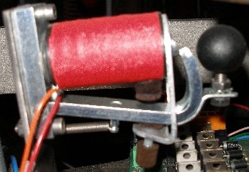
The picture on the left shows a large Black Knight tubular push type solenoid, used for the concussion of a couple of heavy 'bass' castanets as used in our <Simba> robot. In the picture on the right we see a Black Knight tubular pull solenoid used for lifting the pallets in an automated bass accordion. For piano Vorsetzers, push types become the obvious choice.
Inside the solenoids we placed a light helical spring just strong enough to counterbalance the weight of the plunger on the key. In the picture we see Lucas Ledex tubular solenoids with rubber pushers we designed ourselves. If the striking force is in a horizontal plane, it is generally better to use rotating anchor solenoids as used in organ building. The reason is that tubular solenoids operating on a horizontal plane suffer considerably from friction and need springs to return them to the original position after striking. Gravity cannot be used to advantage in this case. Despite this we have applied them in our <Tubo> robot, as there was no alternative solution.
The picture shows a 10 Newton double coil register magnet as produced by August Laukhuff. This type is extremely quiet in operation but not very fast. Brand names for the tubular solenoid types useful in musical robots are Lucas Ledex - now Saaia Burgess -, Kuhnke, Tremba, and Black Knight. For rotating anchor types, August Laukhuff used to be a good source, but they went of of business in 2021. Heuss may be or become an alternative source nowadays. Below are some more applications of different types of rotating anchor solenoids used in automated percussion instruments:
If pulse-only operation is required - as in automated struck percussion, drums, bells etc. - the drive circuit becomes extremely simple:
For ease of interfacing to standard TTL logic levels, we invariably prefer to use logic level mosfets that turn fully on at 5V such as the IRL640. The pulses whose duration's determine the striking force generally come from an output of a small microcontroller, although programmable 16-bit hardware timers (such as Intel 8254) can be used as well. These hardware timers have the advantage that it becomes easy to implement timing resolutions in the order of 0.1 microseconds, using a 10 MHz crystal. With microcontrollers such as the popular Microchip 18F PIC series, we cannot achieve a resolution of much better than approx. 5 microseconds. The resolution depends on how many timed pulses you want to get from a single controller. For a 16-output design, the resolution will tend to be rather in the order of 27 microseconds.
The circuit above is about the easiest one could imagine to implement note-on with velocity, including a hold as required for instruments such as pianos and touch-sensitive organs. The circuit uses a single positive supply voltage. The disadvantage is that a lot of power resistors - one for each note - are required, leading to larger current consumption than strictly needed. From an engineer's point of view it might appear silly to use such a circuit, as you might think it were easy enough to control the power mosfet with PWM. The trouble with PWM however, is that it causes audible artifacts from the solenoids. If you try to overcome these by setting the fundamental frequency way above audio, however, you will run in trouble with the dissipation and eventually electromagnetic radiation (EMC).
Example projects:
The same technology can be applied to the damping of the sound in some instruments, such as the vibraphone. The circuitry for a variable pulse combined with a constant hold voltage is shown below in a circuit as we used it in our <Harma> robot. This circuit is a further development of a similar circuit using darlington transistors as designed by my colleague Trimpin for his player piano, build to make performances of Conlon Nancarrow's piano rolls from midi-files possible.
The circuit can also be created with a small p-channel FET instead of the PNP transistor. The diagram below shows the circuit as we applied it in <Qt> but also - with different power supply voltages and solenoids - in the latest models of our player piano.
By applying PWM (preferably using the lowest possible frequencies for reasons mentioned above) to the hold input, aftertouch can be implemented as well. The effectiveness of such an approach is highly dependent on the mechanical design of the solenoids or valves. Conical valves are the optimum choice if aftertouch is to be implemented. In the <Bomi> robot this was applied. However, although it works pretty well, the final result was too subtle to be really overwhelming.
The positive hold voltage should never be taken larger as the maximum allowable 100% duty cycle voltage for the given coil. Lower voltages will lead to reduced holding force. For player-pianos, this voltage should be choosen such that the force is just enough to hold the key down. The negative pulse voltage should be 4 to 10 times the nominal voltage for the coil. Do not go beyond the maximum rated voltage for the solenoids however, because the insulation of the winding may not survive it. Practical pulse duration's vary between fractions of a millisecond to at the most ca. 50 ms. The higher the voltage, the shorter the pulses can be, and the faster the maximum possible repeat frequency. Magnetization time, frictional losses and hysteresis are limiting factors. If negative voltages larger than -24 V are used, the gate of the negative pulse MOSFET has to be protected with a zener diode. IRF540-type MOSFET's or even IGBT's will be a better component choice than IRL640 in such cases.
An alternative circuit makes use of a fast optocoupler (6N137) to drive the negative voltage MOSFET:
A note on springs:
If push-type tubular solenoids are used to exert a vertical force downwards, as in the case of the piano-vorsetzer, it is generally necessary to fit a helical spring inside the shaft of the solenoid. Although on pianos, the return force of the key generally tends to be large enough to bring the solenoid anchors back, this is a bad practice as it slows down the reaction speed obtainable from the robot. Moreover, the possibilities for nuance will be greatly reduced. The springs should be calculated and fabricated to have just enough force to lift the anchors up at rest. Their length should correspond to the required traject of movement. It should also be noted that these springs need replacement after about 3 or 4 years of daily operation, since they loose force due to material fatigue.
It is also very well possible to use springs the other way round in struck instruments: it a pull solenoid is equipped with a pretty strong spring on the anchor, such that when activated the anchor moves inwards the solenoid, a sound object can be struck on the release of the anchor. Velocity control can be very effective. In fact such mechanisms are often used in industrial electric bells. Examples can be found in our <Bello> robot.
Anchor shapes for tubular solenoids
The drawing below shows the three basic types of shapes for the moving anchors inside tubular solenoids. Both the push and the pull version (if different) are shown.
The first type - the most common in the industry - develops the largest holding force, since the anchor is in flat contact with the end pole of the electromagnet wound on the armature (drawn in red). The big disadvantage is that this type of anchor causes a very high noise level at the moment the anchor hits the pole. This applies even more to the pull type of the same shape. The noise can be substantially damped with a felt washer but obviously this leads to a reduction of the holding end force. The second type shows a tapered end. This type has a much more gradual force against applied voltage characteristic. Therefore we have found that this type is the optimum choice for musical robots in many cases. The noise is damped here as soon as we insert a spring over the tapered end inside the coil former. The smoothest operation, but also the lowest holding force, is obtained with the third type, where the anchor can move freely through the coil. In this case there is no real holding force and the anchor behaves somewhat like a spring on varying loads. This type can be used both for pushing and pulling. The disadvantage is, besides low efficiency, that fitting return springs as well as end stops is mechanically rather difficult.A note on human fingers...
When human fingers activate keys, for example on pianos and organs, there is never a problem with noises at key release. Potential noises are damped by the design of the mechanics of the instrument. However, with instruments such as the accordion, replacing human fingers with solenoids does cause noise problems. In these instruments, when played by human fingers, the keys are released with a damping caused by the stiffness and mass of the human fingers. When we replace these fingers with (tubular) solenoids, the speed with which the keys are released becomes much higher, resulting in lots of noise caused by the sudden (spring-loaded) closing of the valves. This problem particularly plagued the design of our automated accordion <Ake>. It is also relevant for the valve action of valve-operated brass instruments. We propose three different approaches to solving this problem: the first one involves applying PWM on note-off commands such that the solenoids lose magnetization only slowly. However the load on the firmware, particularly for highly polyphonic instruments, quickly becomes prohibitive. Furthermore the remarks with regard to PWM mentioned before do apply here as well. A second, alternative solution makes use of analogue circuitry in hardware:
Here we place a large capacitor in parallel over the solenoid. The capacitor is charged on turn-on by the MOSFET via Rr. This resistor should be sized at about 5 times the value of the DC resistance of the solenoid used. When the MOSFET is turned off, the capacitor discharges via the series diode into the solenoid. The RC time corresponds to the product of the solenoid's DC resistance and the value of Cr. Practical values for Cr are in the range of 1mF to 10mF. Since capacitors with these values invariably have to be electrolytes, they tend to be rather large. The RC time should be below the inverse of the maximum repetition rate for notes (in Hz), one wants to achieve on the instrument. A third solution, also involving analogue hardware, operates similarly but this time on the gate of the MOSFET. Although the circuit is very simple and does not make use of large electrolytic capacitors, it suffers from the large spread in the analog gate drive characteristics of the power mosfets we prefer to use. The circuit also affects turn-on time. But the main problem here, using the mosfets as slow switching devices, is that it will increase their dissipation quite a bit. Thus the space (and expense...) you gain by avoiding the large capacitors in the second solution is lost in the space (and cost) needed for the increased cooling requirements on the power mosfets. All of the proposed methods have been but into practice by us. Our favorite for a long time was the second one, despite the large space penalty involved. For the <Pianet> robot, we experimented with the soft-release via the gate circuit method:
One has to experiment a bit with the C and R values here as they depend quite a bit on the characteristics of the MOSFET used. Also, it is important to use a low drop diode here: a Schottky type, or even a germanium diode. If 3V3 processors are used, this will be mandatory as the choice in power MOSFET's turning fully on with less the 3 V, is pretty limited.However, the problem for all solutions presented here is that they invariably introduce a limitation on note repetition speed. Any solution we can think of for this problem requires looking ahead in software: if we know what the next note will be, we can adapt the release time accordingly. Obviously, this is not possible for a robot that is supposed to operate in real time and without any latency.
A note on the law of the hammer
Instruments whose sound is produced by striking an object with a beater follow the same physical laws that govern those of the hammer. The energy of the collision equals the mass of the hammer multiplied by the square of the speed at the moment of the collision divided by two:
Therefore it seems more profitable to increase and control the speed of the hammer rather than its mass. Increasing the speed was traditionally (in pneumatically driven automata) done mostly by using a longer handle on the hammer. This approach, however, is severely detrimental to repetition speed, since the movement trajectory becomes much longer as well. With solenoid-driven beaters, the mass of the anchor has to be taken into account when it is rigidly coupled to the beater. Magnetization time limits will put limits on the maximum obtainable speed. The smaller the mass of the anchor, the faster the speed can be, but of course the impact will also be lower. As a general rule, one should take the mass of the hammer to be somewhere between one tenth and one twentieth of the mass of the object to be struck. From there one can start calculation of the required trajectory of movement in order to get the desired maximum amplitude. This will lead to quite good specifying possibilities for the solenoids to be used. Experimentation will be mandatory in almost all cases. It might be good to review the elementary mechanics describing collision in general:
Note that for an object at standstill, the second term on the left will always be zero. The value of v4 will be proportional to the amplitude obtained. It depends on the elasticity of both beater and object.Applying textbook physics formulae it is fairly easy to properly rate and design solenoid-driven hammers. If we take s as the trajectory of the hammer (we assume the beater is rigidly connected to the anchor of the solenoid such that we can consider the moving assembly to have total mass m), then, given the response time of the solenoid (this data can be read from the datasheets provided by the supplier for a wide variety of operating conditions), we can calculate the force involved using Newton's second law:
A note on clamping diodes:Inductors switched by semiconductors (MOSFETS, IGBT's, transistors...) almost invariably are used with a diode across them to dampen the inductive reaction of the coil at turn off. This practice is dictated by the need to protect the switching semiconductor against voltage surges. Without protection diode the voltage peak can reach values over ten times the nominal voltage applied over the circuit. The problem one can encounter with this diode, is that it extends the duration of the magnetization in the coil. To speedup the solenoid movement, one could use a power zenerdiode instead of a normal silicon diode, rated for somewhat below the maximum allowable voltage over the semiconductor. However such diodes tend to be rather expensive. If bi-directional solenoids are used, a quite clever trick can be applied to speedup the action and at the same time implement an electric return spring:
In this circuit, the inductive reaction is used to activate the second half of the winding as soon as the diode starts to conduct.2.- Automata where the sound originates from a wind flow
examples: pipe organs, accordions, reed organs, wind instruments (flutes, brass and reed-woodwind)
2.1: - Global wind pressure control:
This can be easily achieved through frequency control of the compressor motor. The speed of the possible modulations is limited by the large inertia of the motor and compressor blade combination. The modulation affects the entire instrument. The motors should be 3-phase AC induction motor types. Collector motors (universal AC/DC motors) cannot be used for they are too noisy in operation. We once used one in our <Melauton> robot and could not avoid the 'vacuum-cleaner' effect...
Example projects:
- Krum
- Vox Humanola
- Piperola
- Bourdonola
- Harma
- So
- Autosax (versions 2 and 3)
- Bono (versions 1 and 2)
- HarmO
- Bomi
- Pos
The easiest practical solution invariably involves the use of a programmable industrial motor controller module as made by Siemens (Sinamics series), Lust Gmbh, Control Techniques, Hitachi.... These controllers all feature a 0-10V dc control input for speed control of the 3-phase AC motor. Details on programming these controllers can be found in the relevant sections of the projects under the hyperlinks provided above. We found - with hindsight - that it was not worth the trouble of designing these things ourselves, since the cost turned out to be higher than the readily available solution.
The steering DC voltage is most easily derived nowadays from a PWM output on a small microcontroller. The PWM is simply filtered with an RC combination and rescaled to the required 0-10V range. Often this rescaling step can even be left out, since most motorcontrollers can be programmed for the optimum range. Obviously a DAC convertor can be used as well, but generally speaking it is overkill in most cases, since the speed of change is very low and it costs us a minimum of about 8 I/O pins on the microprocessor. For faster braking, it is advisable to program the motor controller to use DC injection in the windings. Braking resistors may be used as well.
Note that wide control of operating pressure on reed pipe based instruments can be very problematic, since reed pipes do not maintain their tuning very well when exposed to varying pressure. This problem is nonexistent with flue pipes. These pipes also only maintain pitch over a small range of pressure variation, but at least they always return to the original pitch as the wind pressure returns to the nominal tuning value.
A special consideration should be given to the implementation of wind pressure and flow control in reed organ type instruments such as reed organs, accordion, concertinas, melodicas and such more. In these instruments pitch is largely unaffected by windpressure and windpressure mainly determines the sound volume. Other than in pipe organs, here it is not a good idea to regulate wind pressure to any constant value. Instead, motor speed -and thus airflow- ought to be a function of the notes playing and the registers effectively drawn. Keep in mind that a low 29 (the lowest key on an average reed organ) draws up to 64 times more air than a high 101 (the highest note on larger reed organs). A simple lookup algorithm should be build into the firmware of the motor controller:
For i = 29 To 101
Note_Air[i -29] = ((101 - i) / divider) + 1
Next iThe lookup thus produced (we used a divider value of 16) should be multiplied with a factor according to the register(s) drawn. For an 4' register x2, for 8' x4, for 16' x 8. The value thus obtained should be added to the value of the user requested volume setting. A worked out and tested firmware for such an implementation can be found in the website pages documenting our <HarmO> robot. Obviously the motor controller used has to be programmed for maximum possible reaction speed. If such 'intelligent' motor control is not implemented, the instrument will be very noisy and often leaky.
Although, as said, the used of standard motor controllers is most often the cheapest and easiest solution, there are cases were the design of a suitable motorcontroller becomes mandatory. The storm wind module in our <Thunderwood> robot is operated by a blower with a 3-phase 400 Hz / 208 V drawing 0.14A current. Standard controllers are not suitable in this case, so we designed a motor controller using a Microchip 24EP128MC202 microprocessor. The circuit we developed is:
The firmware implements braking by reversing the direction of rotation. The base frequency of the PWM is 117 kHz and used to generate variable amplitude sinewaves shifted in phase angles of 120 degrees. The motor frequency can be controlled between 40Hz and 400Hz and motor voltage is proportional to motor speed, thus protecting the motor against overheating. The firmware is available as well.For our automated siren in <Balsi. we used a very similar approach, but here we implemented a full PID algorithm in the firmware, as precise speed control was mandatory in order the generate precise pitches. The motor control firmware builds on a pretty straightforward PID regulating loop. Here is the algorithm, coded in Power Basic:
FUNCTION PID (BYVAL sollvalue AS SINGLE, BYVAL seinvalue AS SINGLE, BYVAL OPT kp AS SINGLE, BYVAL OPT ki AS SINGLE, BYVAL OPT kd AS SINGLE) EXPORT AS SINGLE
' The machine constants have to be passed on the first call only. Seinvalue is the measured reality value, generaly derived from a sample. Sollvalue is the goal we want to achieve. The function returns the correction factor for regulation and should be used in a regulation loop.
STATIC propconstant, integrationconstant, differenciationconstant AS SINGLE
STATIC oldfout, iterm AS SINGLE
LOCAL fout, pterm, dterm AS SINGLE
IF kp THEN propconstant = kp
IF ki THEN
IF ki <> integrationconstant THEN RESET iterm ' reset! integrationconstant = ki
END IF
IF kd THEN
IF kd <> differenciationconstant THEN RESET oldfout ' reset differenciationconstant = kd
END
IF fout = sollvalue - seinvalue ' calculate the error pterm = propconstant * fout. Proportionality term iterm = iterm + (integrationconstant * fout). Integration term dterm = differenciationconstant * (fout - oldfout)
oldfout = fout
FUNCTION = pterm + iterm + dterm ' return value for the PID correction signal
END FUNCTION
Here is the circuit wherein this was implemented:
2.2:- Using fans
Regular fans as used for cooling in all sorts of electronic devices make perfect wind sources for sounding cavity resonators. Such resonators work best on low pressure turbulent suction wind. Here we are talking only about DC operated fans using BLDC motors, generally operating on voltages such as 5V, 12V or 24V. Some types have a separate wire connected to a sensor and allowing you to read the speed of rotation.Example project:
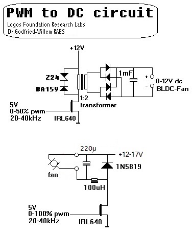
Controlling the speed of rotation of fans is less straightforward than one would think. The reason being that the motors driving the blades of fans are BLDC motors. They contain quite some complicated circuitry to commute the different windings on the anchor. If you try to control such fans with a PWM voltage, you will get very unreliable results and eventually you will also ruin the fan. It is mandatory the steer these motor-assemblies with pure DC. This calls for a reliable PWM to DC convertor.
Here are two tested and useful solutions:
The first circuit has the advantage that the motor can be fully floating with respect to ground. However, finding suitable transformers is often a practical problem. The second circuit is simple, but you have to make sure the inductor can handle the required current. The capacitor must be a low ESR type.
Some -generally somewhat more expensive- models are available that can be controlled with PWM signals directly. Sanyo has quite some types in their catalogue. Here is a circuit drawing for a second <Whisper> design using fans with PWM control inputs:
In this application we did not use the sensor signal wire, drawn in blue in the above schematic, but it's easy and straightforward to implement if needed. Note that in this design we used 12V linear voltage regulators as high-side switches. These are 4-lead devices with an enable input. The datasheet gives no details as to the allowable switching speed on this input; not a problem in this application but be warned if ever you try to use these components in fast switching applications...
2.3:- Wind flow control: through valves.These can be operated pretty fast, driven by either stepping motors or servos. Valves can be used to implement a tremulant in some cases.
Example projects:
In the accordion robot <Ake> we constructed a large 4-way valve capable of smooth switching between suction and pressure wind with all gradations in between. Our first idea to operate this valve with a bi-directional solenoid didn't work very well. The later use of a stepping motor in combination with a Melexis position sensor works nicely. In <Qt> we used a similar design for the wind flow control.
Note that commercially available solenoid valves can almost never be used in this area of applications. They are not available with large enough orifices, they can generally only operate at pretty high pressures (1 - 20 Bar) and last but not least, they make a lot of noise.
The stepping motors are inherently a bit noisy. If this is to be avoided, a very good solution is to use soft shift solenoids as produced by Lucas Ledex. They provide very smooth operation and work very well for flow regulation and tremulants in organs. However, their force is limited. The application of such a device in combination with a conical valve (see further) under PWM control in our <Bomi> robot proved to be a great success.
The bellows can be operated either with a motor and a crank, or with a motor coupled to a trapezoidal threaded rod, or else through a (very expensive) linear motor. Good and responsive control is possible.
Example projects:
If a trapezoidal threaded rod is used, it is best to drive it with a brushed DC motor and an appropriate controller. The starting torque should be very high to overcome initial friction. Sensors are required to limit the trajectory of the bellows. For precise control of the wind pressure, the low pressure sensors offered by Freescale may form the basis of a good PID-controlled loop. (Cf. Bako).
2.4.: Individual control of notes:
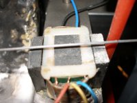
Here the use of conical valves operated under PWM becomes mandatory. The picture shows the mechanism. The cone is covered with fine leather or a synthetic material such as polypel.
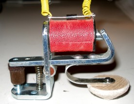
Conical valves can also be operated with tubular solenoids. As an alternative, moving coil valves, which can be made from re-engineered loudspeakers, can be used as well. In the latter case they can be driven with bipolar analogue DC current (double H-bridge). This technology not only allows control of the individual note attack, but also note aftertouch. Furthermore, it is possible to operate each note with an individual pump, driven by a solenoid, as we did in <Puff>.
The picture shows the mechanism involved: underneath is a tubular solenoid (Lucas Ledex type) pushing the anchor on the carbon-compound plunger inside the glass cylinder (Airpot). In this case we used a single-pulse driving circuit as described before for use in percussion instruments. However, if you go that far, it becomes difficult to obtain sustained notes unless at least two pumps are used for each note. With a single coil/pump combination you can get at the most a steady flatterzunge (flutter-tonguing).If the requirements as to the control range of attack and/or aftertouch are not too critical, flat solenoid-driven pallets can be used.
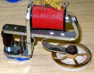
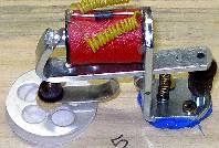
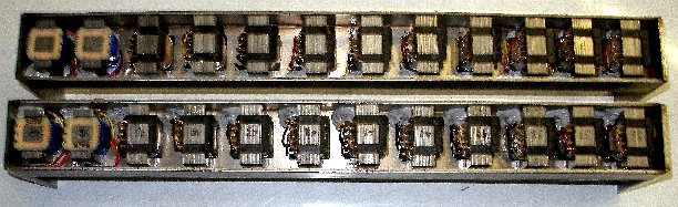
The types shown on the pictures are made by August Laukhuff: the left one has a 35 mm pallet, the right one 40 mm. These types can easily be converted to operate conical valves by exchanging the flat pallets with conical ones, as shown in the first picture under this heading. For good velocity control, the original springs must be replaced with a stronger type. Details can be found in our pages on the development of our 6-octave quartertone organ <Qt>.2.3:- Wind modulation and control through bellows.
The laws governing airflow control through round flat valves are:
The fundamental problem with gradual control of valves with solenoids is that the trajectory for the opening versus applied voltage is normally very steep, and furthermore the working trajectory is different for opening and closing. The graphs below give typical curves:

The last curve depicted represents the best possible compromise, obtained by using conical valves in combination with a much-increased spring force.Examples of projects:
- Qt (flat valves with individual note aftertouch)
- Puff (individual solenoid-driven pumps for each note)
- Thunderwood (bird mechanism)
- Bomi (conical valves with individual note aftertouch)
In some of our early automata (<Piperola> and <Vox Humanola>) we used direct-acting solenoid valves to steer the windflow to the pipes. Such valves cannot be used off the shelf unless you are prepared to live with the loud clicking noises these valves produce at switching. To overcome this, we shortened the ferromagnetic anchors inside these valves by some 3 to 5 mm on the lathe, replaced the back end with a circular piece of felt, and reduced the force of the return springs. Although it is possible to use these valves for velocity control of the note attacks by steering them with PWM or variable DC, the results are quite disappointing because the valve response is quite unpredictable. Ultimately, the valves work nicely as switches, but when you make the final bill, it comes out to be about twice as expensive as using regular valves as described before. The only areas of musical automata where these solenoid valves become the device of choice are automated, tuned, membrane-driven car horns or ship horns driven by compressed air (1 to 6 Bar pressure). <Toetkuip> and <Klankboot> are two open-air projects that illustrate this.

Solenoid valves can be operated either on AC or DC, but for automated instrument use, only DC should be considered, since when driven with AC you will get a 50Hz buzz enriched with overtones from each of them...A note on conical valves:
As noted above, the use of conical valves becomes mandatory if one wants to implement fine individual note aftertouch in windblown instruments. Since the solenoids to be used have a limited trajectory of movement (Tr) and proper design entails that the surface of the inlet orifice should equal the surface of the valve outlet (the surface of a cone segment or the side surface of a frustum) when fully opened, it follows that the angle of the cone becomes an essential design parameter. To facilitate calculations, we provide the essential design equations below:
The technical problem here is in the construction of the valve seating, rather than the valve cones themselves. The latter can be fabricated easily on the lathe or purchased from sources such as A.Laukhuff. The smaller the diameter, the smaller the angle, and they can be ordered in 7 different diameters. But in order to make the conical holes in the windchest one will face the problem of milling holes to these exact angles, not conforming to standard available conical mills. Most of the time it cannot be done on the lathe for the shapes of regular windchests (solid plates of wood or a synthetic material) make it impossible. If you do not have a CNC milling machine, the only solution we have found was to use custom-made mills that can be used in a regular drill. This tends to be very expensive. So far we have only taken this route for our <Bomi> robot, for which we used five custom-made mills. Of course, once you have a set of suitable mills made, the tools can be used for many more robots and the price will come down proportionally.Here, as an example, is the result of the calculations as performed for the construction of the conical valves in our <Bomi> robot, using A.Laukhuff cones. The last two columns give the result of the calculations if flat valves had been used - for the same orifices: the regulation superiority of the cones will be obvious.
cone diameter top angle trajectory diameter of equivalent orifice flat pallet trajectory 35mm / 15mm 110° 5.2mm 10 mm >=15mm 2.5mm 25mm / 12mm 100° 5.0mm 7 mm >=10.5mm 1.75mm 20mm / 11mm 85° 6.0mm 5 mm >=7.5mm 1.25mm 16.5mm /10.2mm 81° 6.0mm 4.3 mm >=6.7mm 1.1mm 13mm/ 8.7mm 72° 6.0mm 3 mm >=4.5mm 0.75mm The diameter of the equivalent round orifice should be taken such as to correspond to the diameter of the inlet of the organ pipes used. By increasing the trajectory a bit, adjustments to the exact sizings of the pipe feet are possible. For Laukhuff pallet valves, the maximum possible trajectory is 10 mm. If you take a trajectory that is too small, resolution of the regulation possibilities will suffer. In our designs using these solenoids we limit the traject to about 5 mm, a compromise between smooth regulation and speed of response. When performing the calculations, one should be sure to choose the equivalent orifices such that they are about 10% larger than the diameters of the wind inlets of the pipes, in order to compensate for losses due to curvatures, turbulence and roughness of the valve surfaces in the windway.
In general, the sharper the top angle of the cone, the smoother the regulation will be, but also, the larger the required trajectory. Thus one should always try to use the sharpest possible cone for the maximum possible traject.
To facilitate these calculations we wrote a small computer program to generate useful lookup tables. The program can also be used for flat valves, if you specify the top angle as 180°. From comparison of the generated data, it will immediately become clear why flat valves make poor regulators but great switches. It can be downloaded freely. (4) Here is a table with some calculated results. The numbers colored red reflect the values for standard conical valves available from A.Laukhuff. The numbers in orange are the results for flat valves operating on the same orifice as the corresponding conical valve.
angle trajectory orifice cone diam >= flat diam >= flat trajectory 170 3 68 68.6 102 17 170 4 90.7 91.4 136 22.7 160 3 33 34 49.5 8.25 160 4 44 45.4 66 11 160 5 55 56.7 82.5 13.8 160 6 66 68 99 16.5 130 3 10.6 12.9 15.8 2.64 130 4 14.1 17.2 21.1 3.52 130 5 17.6 21.4 26.4 4.4 130 6 21.1 25.7 31.7 5.28 120 3 7.79 10.4 11.7 1.95 120 4 10.4 13.8 15.6 2.6 120 5 13 17.3 19.5 3.25 120 6 15.6 20.8 23.4 3.9 110 3 5.75 8.57 8.62 1.44 110 4 7.67 11.4 11.5 1.92 110 5 9.58 14.3 14.4 2.4 110 6 11.5 17.1 17.2 2.87 100 3 4.2 7.15 6.29 1.05 100 4 5.59 9.53 8.39 1.4 100 5 6.99 11.9 10.5 1.75 100 6 8.39 14.3 12.6 2.1 90 3 3 6 4.5 .75 90 4 4 8 6 1 90 5 5 10 7.5 1.25 90 6 6 12 9 1.5 85 3 2.51 5.5 3.76 .627 85 4 3.34 7.33 5.02 .836 85 5 4.18 9.16 6.27 1.04 85 6 5.02 11 7.53 1.25 81 3 2.16 5.12 3.24 .54 81 4 2.88 6.83 4.32 .72 81 5 3.6 8.54 5.4 .9 81 6 4.32 10.2 6.48 1.08 80 3 2.08 5.03 3.12 .52 80 4 2.77 6.71 4.16 .693 80 5 3.47 8.39 5.2 .867 80 6 4.16 10.1 6.24 1.04 72 3 1.51 4.36 2.26 .376 72 4 2.01 5.81 3.01 .502 72 5 2.51 7.26 3.76 .628 72 6 3.01 8.72 4.52 .753 70 4 1.84 5.6 2.76 .461 70 5 2.3 7 3.46 .576 70 6 2.76 8.4 4.15 .691 60 4 1.15 4.62 1.73 .289 60 5 1.44 5.77 2.16 .361 60 6 1.73 6.93 2.6 .433
Although conical valves allow for a much better flow control than flat valves, both types show a linear characteristic within their trajectory of movement. The difference is that the steepness of the curve is much lower in the case of conical valves. Trajectories other than linear ones are conceivable and possible: one could use ball valves, parabolic or hyperbolic, thus realising all sorts of trajectories that can be described in a second degree equation. We have never gone that far in practice, because we do not have access to the required machinery to make the valves and their seats. Only spherical mills as well as a wide variety of balls are readily available. Here is the required maths relating to the calculation of ball valves:
It will be clear that as one increases the diameter of the ball, we come closer to the behavior of a flat valve. Thus, for optimum regulation the ball diameter should be as small as is practical, but larger of course than the orifice to be regulated. The mechanism used for the sound generation in version 2 of our <So> robot, an automated sousaphone, makes use of a spherical valve to control the mouthpiece.A note on tap-tones in organs and wind instruments with fingerholes:
2.5.: Very fast air pressure modulation:
Unrelated to the regulation characteristics, there is another say for the use of conical valves in organ windchests. Particularly when applied in 'digital' on-off switching, conical valves make a lot less noise that flat valves. From an aerodynamic point of view it seems evident that cones will reduce turbulence around the edges of the windpath. But, this is not the main reason why we got to prefer cones. A flat pallet, on closing the windinlet to the pipe, causes the cylindrical bore of the windchest upperplate coupled to the wind channel in the pipe foot, to resonate. The closing action of the valve is solely determined by the spring force of the return spring. Much like what happens if we tap with our flat hand the open end of a piece of pipe. This leads to a quite noticeable pitched percussive sound, a tap-tone in pitch completely unrelated to the pitch of the organ pipe. By applying conical valves, this unwanted sound can be reduced considerably. This tap-tone is typical for pallet valve switched pipes and does never arise in traditional mechanical organ building, where sliders in the windchest are used to switch the notes. These sliders inherently have a relatively slow attack and decay, which counts for their inferior clarity of speech when compared to flat valves.The best (and cheapest) technique to achieve this in instruments operating under an air pressure not exceeding 200 mm H20 (20 mBar), is through large bass loudspeakers placed inside the windchest. These make very good tremulants as well.
We have been using loudspeakers as valves, air pressure modulators and even compressors since the early seventies. Since loudspeakers are moving coil devices by design, the low moving mass is responsible for their excellent responsiveness. Note that the loudspeakers are driven with sub audio frequencies (and even pure DC if used in a valve) in these applications. In any case, one should stay way below the resonant frequency of the loudspeaker.
You can even take this design a step further by using the speaker as a vibrating membrane coupled to a resonator, thus coming close to the diaphane register found in some 19th century pipe organs. It is a good way to achieve strong-sounding basses in relatively small volumes. However, one could question here the extent to which one can still consider such an instrument to be 'acoustic' and not as loudspeaker-sound driven... In any case, this does not seem to be a either/or question, since when properly analyzed, a continuum shows up between purely electronically generated sound and acoustically generated sound. In version 2 of our automated sousaphone <So> as well as in the first versions of <Bono> for instance, a moving coil mechanism is used to make the silicone lips vibrate against the mouthpiece. This modulates the air flow coming from a small compressor and causes resonating sound from the connected instrument. These instruments do sound 'faulty' notes at times and occasional multiphonics. But, if we drive the instrument directly with a moving coil compressor driver, as we did in in the first version of our experimental cornet <Korn>, the sound is determined to a much larger extent by the electric signal applied to the driver as the acoustic coupling to the instrument is a whole lot lower than in the first case. Here 'faulty' notes simply cannot occur. This last concept is therefore a borderline case as one could consider it to be simply a nonlinear loudspeaker.
2.6.: Acoustic impedance convertors for a pressure-driven monophonic wind instrument
When thinking through the acoustical function of wind instruments, be they lip-driven or reed-driven, the basic principle is always an air column with an adjustable resonant frequency coupled to a driver. In order to obtain proper resonance, the driver should not be too stiff or frequency- selective. It should be very low impedance since the resonator will convert high pressure and small amplitude at the mouthpiece side into low pressure and high amplitude at the point of contact with the surrounding air. Thus a wind flow does not appear to be essential for the acoustic functioning of a pressure-driven instrument. Human players however, can only make their lips vibrate (this also applies to reeds of course) by directing a windflow and using the elasticity of either lips or reed. If our muscles were only fast enough, we could play the instrument without using our lungs. This analysis led us to the development of sound compression motors coupled to properly designed acoustic impedance converters as a replacement for lips and reeds in wind instruments. Note that this does not apply to air flow-driven instruments such as flutes, which we have treated above. We come back to them later though. Pressure-driven instruments acoustically behave as resonators closed at the driven end. Instruments developed according to this line are:
If the impedance converter is well designed (the orifice ought to be as small as is reasonable, although this is done to the detriment of sound pressure), the waveform of the driving signal, provided it has enough partials, becomes fairly unimportant and the instrument will produce a sound pretty close to the sound obtained by players.
However, attack and envelope will have to be controlled by the electronic driver using amplitude modulation. If this is left out, the sound produced will invariably sound synthetic, particularly on sustained notes. In all our robots making use of this technology, we have implemented a wide range of expression controllers for this purpose. Particularly for the higher pitched instruments, this approach was very fruitful. The reason why it is so difficult to make a fully mechanical sound source for these instruments is that the required speed of movement and the mass to be moved are too high for electromagnetic devices. From this constatation, it becomes logical to examine the possibilities of realizing the mechanical sound sources on a sub-miniature scale and picking up the vibrations with transducers. These signals, after amplification, can then be used to drive the acoustic impedance convertors. The resulting sound is a lot more natural than what can be obtained with synthesized waveforms. However, such an approach cannot be used if one wants to automate existing instruments. An alternative way to improve sound results with digital oscillator-driven impedance convertors consists of using audio feedback from the instrument and using this signal to modulate the driving signal in the software. This however, requires very fast processors. If the frequency range is limited, the acoustic impedance converter can also be equipped with a mirliton-like resonator in the embouchure part. Good results require many days, if not weeks, of experimenting with different materials and geometry's.Compression drivers are produced by different manufacturers either for use in public address sound reinforcement systems where they are coupled to exponential horns (megaphones), or as tweeter drivers for speaker systems. In fact they are like loudspeakers - moving coil devices - but lack a sound- projecting membrane. The specifications vary, with powers ranging from 5 W up to 150 W and impedance's such as 4 Ohm, 8 Ohm, 16 Ohm, 800 Ohm etc. If you are designing automated instruments using acoustic impedance converters as described above, you should be aware of the fact that the load on the driver represented by the converter changes the impedance of the driver considerably. Also, the impedance depends on the driving frequency. So for example, one of the drivers we have used (a driver made in china rated 100W at 16 Ohm) has an impedance of 15 Ohm at 1 kHz with no acoustic load. However, when loaded with an impedance converter with a long capillary, the impedance, measured at the same frequency of 1 kHz, rises to 32.8 Ohm. At 100Hz (measured impedance 11.4 Ohm) or at 10 kHz (measured impedance 26.7 Ohm), the loading effect on impedance is substantial. These facts dictate the need for linearising or equalizing lookups at the generator firmware level or in the amplifier stages.
It is also important to understand the way compression drivers work: if they have a membrane with surface Sm and they are loaded with a horn with an orifice Sh equal to Sm, than then the compression ratio Sm/Sh is unity. In audio applications, the compression ratios are in the order of 2 to 4, meaning that the surface of the orifice of the load, Sh is only half to one quarter of Sm. In the interest of a natural sound, the compression ratio for automated instruments should be set as high as practical. The upper limit is where the air compression starts hindering the movement of the membrane too much. Taking into account these considerations, our decision to use a tweeter driver in our oboe robot <Ob>, becomes logical. The compression ratio in this robot is about 1:25. In fact one could also approach this acoustic impedance convertor as a de Laval nozzle, a device for which the mathematical theory is very well developped. (cfr. R.Courant and K.O.Friedrichs, 1999).
The electric signal for the compression driver can be obtained in two different ways: either one can make use of a suitably designed audio-type amplifier, or one can generate the power signal directly using two phase- shifted PWM outputs on a dsPIC type microcontroller. In the last case a custom designed power output transformer (push-pull) may be required to match the impedance of the compression driver.
The circuit as we used it for our automated oboe <Ob>, as well as for <Korn> looks like:
The problem we encountered with this circuit is that amplitude control becomes only possible by changing the duty cycle of the PWM signals driving the power mosfets. On low amplitudes, artifacts will become audible as the resolution (limited to 16 bits) of the signal goes down with the amplitude. This interdepency can be solved, by introducing a third PWM source driving a P-channel power MOSFET in the positive power line driving the compressor motor, as shown in the drawing below:

Note that the base frequency of the amplitude PWM signal has to be well above 20kHz for good results, even with the 10mF capacitor present to filter out the modulation frequency. The problem with this circuit is that at a PWM base frequency around 100kHz, it is very hard to find power mosfets that switch fast enough. Also, this circuit is not very power efficient, as about half of available power gets dissipated in Rx, a high power resistor. In a preliminary version of our <Fa> robot Rx was taken as 15 Ohms, matching the impedance of a half winding of the transformer (16 Ohms). For the P-channel MOSFET a IRF9540NPBF was chosen. Since the practical results were quite deceptive, we decided to get back to analog regulation, starting from the same 100kHz PWM signal generated by the dsPIC microcontroller. In the analog approach we use an LT1038 power regulator and drive the adjust pin with the variable resistance from a Silonex optor component, a combined LDR-LED. The complete circuit became:
This circuit works very smoothly although one may find it to react rather slowly to amplitude change commands. The linear regulator (LT1038) is nowadays an obsolete part in a TO3 housing, but alternative parts are available on the market. A LT1083 (Linear Technology Corporation) should work, though Umax on the input is limited to 30 V and maximum current is only 7.5A. We didn't check it at the time of this writing.
The circuit using an audio amplifier, as used for our automated valve trombone <Bono>, as well as for <Autosax> and <Heli> looks like:
Note that a transformer is used in this circuit as well. But since we only have to cope with small signal levels here, ordinary good-quality audio line level transformers readily available on the market can be used. Note that volume control is achieved here by using a third PWM signal to control an Optor circuit (LDR- LED combination). Although these components are highly nonlinear, they helped us in avoiding artifacts on low amplitude levels.For our clarinet robot, <Klar>, we decided to go for a true 32 bit ARM processor in order to avoid artifacts in the volume control which had to be implemented with an extremely large dynamic range (110dB) , dictated by the properties of clarinets. Thus we had the possibility of implementing formant filters, vibrato and tremolo on the controller level. In this case, the power driver is an ordinary high quality audio amplifier.
In the <Bug> robot, finished January 2017, we used a Microchip 24EP128MC202 16-bit microprocessor to steer the membrane compressor. This is the circuit:
In this circuit we use analog multipliers for modulation, thus relaxing the firmware somewhat as compared to a pure digital approach. Another important advantage here is that we do not suffer from audio artifacts, difficult to avoid in digital designs using pretty simple processor chips.
Excitation wave forms
Acoustic researchers for a long time have been looking into methods to capture the source of the vibration in wind instruments. Practical methods to measure and record to vibration of lips or reeds on wind instruments directly, never lead to convincing results, as the transducers influence normal sound production to a great extend. Hence our idea to derive the vibration of the excitation source indirectly. A now verified method to generate the required waveform lookup tables for driving the membrane compressor we developed and tested thoroughly in 2020 consists of the following steps:
1. Excite the membrane compressor with a waveform (at least 4 periods are required and these must be looped in the firmware) corresponding to what you would like the robot to sound like. Lets call it WavIn(). This waveform must be without any modulation and recorded in an anechoic chamber using high quality microphones at a distance not larger than the size of the sound source. This signal can best be derived from a recording of the instrument played in the traditional way. So, it should be recorded prior to modifications required to build the actual robotic instrument. Make sure you record sound samples for a large series of different notes in different dynamics and registers as excitation waveform differ greatly in function of these parameters.
2.- Record the sound of the robot, using a high quality microphone, with this excitation and convert it to a format suitable for the microprocessor selected. Lets call this waveform WavOut() . Make sure the sizes of WavIN() and WavOut() are the same and take care to align the phase as well as possible. This is a quite tedious job, in particular for instruments where the contribution of the instrument to the sound result is relatively small as compared to that of the playing style, the mouthpiece etc. For the saxophone this is noticeably the case, whereas we had less problems in this respect with the oboe and the flute.
3.- Calculate the required excitation waveform as: WavEx() = (2 * WavIn()) - WavOut(), in the time domain. Normalize this wave and remove any DC components. This wave is a model of the excitation wave deprived from the influence of the instrument. Of course this cannot be fully true, as it doesn't take into account the mutual coupling of excitation and instrument. However, the model does work quite well on practical robots of enough waves are prepared to cover the different registers and dynamic levels.
4.- Reprogram the microprocessor to use WavEx() as an excitation waveform for as many notes and dynamics as the microprocessor can cope with.
This method was applied in the construction of the <Flut> and version 3 of the <So> robot in 2020. Of course, the procedure ought to be performed for a note in each register the instrument is supposed to sound. It would be ideal -but tedious- to follow this procedure for each individual note. However, the microprocessor used should than have a very large memory. The 16 bit 24EP128MC202 types we prefer to use, are limited to 16kBytes, enough for a maximum of 10 wavetables, 1024 bytes each.
The theory behind this approach is that the excitation-wave should correspond as much as possible with the vibration of the lips or reeds that cause the vibration in the instrument. As it is nearly impossible to capture this vibration by direct methods, we reason that the sound produced by the instrument is the sum of the excitation and whatever the instrument adds (or omits) to it. Thus, by sending a sample of the normally produced sound to the membrane compressor, we should get the excitation wave plus twofold the contribution of the instrument. By calculation of WavEx() = (2 * WavIn()) - WavOut() we get a model of the exitation wave. When studying and analysing waveforms produced by real instruments, you will notice that in fact no two periods are the same, neither in shape, neither in length. That's why we take a minimum of four full periods. Do not use more than say 16 periods though, because it may introduce subharmonics, if not even rhythmical pulsation's in the sound on long notes. With four periods, you get a very soft subharmonic two octaves below the sounding pitch. For this reason we always add a tiny amount of jitter to the sampling rate. In theory it should be a Gaussean, but in practice straight random jitter over a narrow range leeds to very acceptable results. No two periods have exactly the same length, just as in humanly played wind instruments.
Pitfall's and limitations of this method:
When the sound waves are recorded using the standard sampling rate of 44.1kS/s, the highest note we can sample for the here required resolution of 128 samples per period is 44.1Hz / 128 = 344.5Hz. This corresponds to midi note 64. The following graph shows a flute sample for C (midi note 60):

It will be clear that perfect results require sampling of the wave at a sampling rate equal to 128 times the frequency of the wave to be sampled. Thus for the highest possible midi note 127, this would dictate a sampling rate of 12543.8 Hz * 128 = 1.606 MS/s. Clearly impossible on PC's. From an audioperception point of view this is of course greatly exaggerated a requirement for such high frequencies. Also, one would get in great trouble when trying to generate waveforms at such a high sampling rate on a microprocessor platform. Nevertheless, there is clearly a say for the use of as high as possible sampling rates. The 192 kS/s sampling rate offered on some of the better sound cards in PC's will lead to good results up to 1500 Hz, or midi note 90. This is more than enough for any practical application in automated instruments. As to vertical resolution, the commonly used 16-bits are more than what we really need. So going to 24 bits is overkill. On the 16-bit microprocessor platforms we have used so far, it's already hard enough to reach a resolution of 12 bits.Also, it is important to keep in mind that the fact that there is no common divider between the sampling rate and the pitch leads to slight detuning of the generated notes. Tuning can only be guaranteed to be precise if the sampling rate divided by the frequency of the note is an integer. As equal temperament leads to frequencies that can only be expressed as irrational numbers, this problem cannot be circumvented.
Practical application of this method are documented in the source code for the firmware of the robots <Flut>, <So>, <Autosax>, <Bug> and <Hunt>. Utilities to calculate, display and manipulate the required wave lookup tables are integrated in the DLL libraries of our GMT software.
3.-Instruments where the sound originates from, or is influenced by rotation, rotating or linear friction such as in bowed instruments, sirens, the rotating valves in vibraphones, the tremulant in reed organs etc.
Technology to be used: Frequency control of AC motors, PWM control of DC motors, linear motors, servos and/or stepping motors.
Example projects:
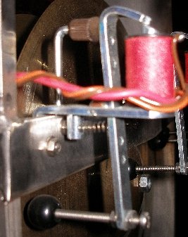
A particularly difficult problem is encountered whenever one attempts to automate bowed instruments. The pressure of the bow against the string as well as the bowing speed have to be controlled in great detail. To control the pushing pressure of the bow against the string, softshift magnets driven with variable DC or PWM can be used. The picture shows the mechanism used to achieve this in our automated hurdy gurdy where we use a rotating round belt as a bow.
Note that these softshift magnets, although extremely expensive, are devices that respond relatively slowly. The forces involved here preclude the use of moving coil mechanisms. Pneumatic cylinders would be ideal here, if they didn't suffer so much from exhaust noises...
The rotators in vibraphones can easily be driven with 7.5 degree per step stepper motors. To avoid noises, it is best to drive the rotating shaft with a rubber or nylon belt. The same principle can be applied to the typical Doppler-based vibrato mechanism found on many larger reed organs. On the original instruments, this rotator - functionally very similar to the Leslie effect - is driven by a simple pneumatic motor. The disadvantage is that the vibrato speed becomes intrinsically dependent on the wind pressure and thus the sound volume. By replacing the pneumatic motor with a silent DC motor (we have used tape recorder motors for this with great success) we can control the vibrato speed independently. We also found that replacing the blades - normally made from cardboard - with more reflective material such as polished steel (thin Hasberg measurement blades) makes the entire mechanism a lot more effective.
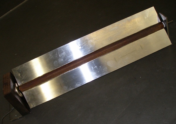
The picture shows the tremulant mechanism as we made it for our <harmO> robot.In our <Tubo> robot, we used DC motors with an eccentric wheel to move the pipe resonators over a small trajectory over and back from the center of the aluminum sounding tubes.
4.- Instruments where the sound originates from shaking.
Maracas, Angklungs, bells, shakers, thundersheets etc.
Bipolar electromagnets or solenoids can be used, with single pulse-time control in both directions. Useful solenoids can be found in the catalogues of Kuhnke, Emessem as well as August Laukhuff, where they are presented as register traction magnets. Shaking frequency is limited to the low frequency ranges, up to about 30 Hz. For medium shaking frequencies, motor- driven vibrators can be used.
4.a: Bipolar electromagnets
Example projects:
- Klung (automated angklung)
- Springers (maracas)
- Psch (steel sheets)
- Thunderwood (thundersheet, bamboo chimes)
- Whisper (tiny maracas)
- Tinti (tintinabuli)
- Chi (orchestral chimes)
For small objects (bells and rattles) bistable electromagnets as used for registration knobs in organs can be used:
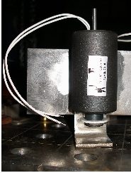
The type shown uses two separate coils. By steering them with two independent PWM signals, you can get intermediate positions easily. For good control, a position sensor and a PID regulating system is required. These double solenoids are -by the way- also very suitable for the implementation of plucking mechanisms on strings if you can live with the very low force they deliver. For larger loads and forces, the solenoid shown in the picture below is suitable. Note that solenoids with higher forces - and thus more moving iron mass - also inherently have a much slower response. We used this type in <Klung>, our automated angklung.
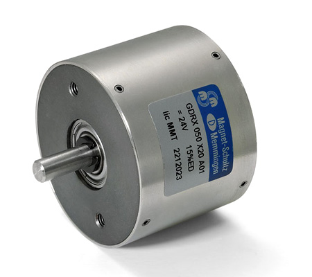
A type made by Emessem in the UK (since 2007 named Magnet-Schultz Ltd.) looks like this:
If the shaking frequency needs to be very high or very randomized, once again cheap loudspeakers can be used, as we did in the rain-mechanism in our <Thunderwood> robot. When solenoids are used, they should have two different windings. The choice of commercially available bi-directional solenoids is extremely small. For some applications it is possible to combine two solenoids to implement bi-directional movement without using return springs. This is what we ended up with in the design for the rotary valve mechanism in our automated trombone: <Bono>. It is not too difficult to make bi-directional solenoids yourself provided you have a lathe and some winding experience.
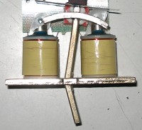
4.b: Motor-driven vibrators.These devices have applications in a wide range of industrial processes: sieving, mixing and separation of granular components... They consist of a motor (generally a 1 or 3-phase AC induction motor) with a protruding axis on both ends onto which eccentric weights are mounted. By adjusting the position of the weights, the amplitude of the vibrations can be regulated. In applications for musical automata where fast shaking is a requirement, good control of rotational speed as well as amplitude becomes a requirement. For AC motors, standard 3-phase motor controllers can be used. If control of acceleration and amplitude is required, the same technology can be applied but one should preferably opt for hybrid stepping motors. Steering the magnitude of the motor current will yield a good control over vibrational amplitude whereas programming of the stepping patterns allows control over the vibrational wave form. In our experiments, shaking frequencies up to 400 Hz have proven to be possible. An intrinsic problem is presented by the vibrator's own resonance's in combination with the load. Under resonance conditions, self-destruction is easily achieved.
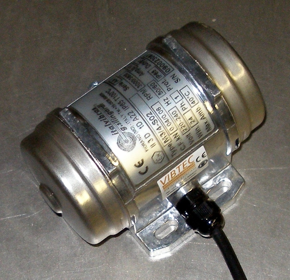
Commercially available AC motor vibrators are available from Italvibras (Italy). Type Vibtec M3/4-S02 is a monophase device with a centrifugal force rating of 2 to 6 kg, powerful enough to vibrate even the largest thundersheets. Models with much higher forces are available from the same source.
The model shown on the picture weighs 850 g and has a power rating of 20 W. It is very quiet in operation. For variable frequency use, we advise using them with an amplified sine wave. Make sure the voltage is reduced when the frequency goes down. If a 3-phase motor has to be steered, following circuit gives good performance over a wide frequency range, in fact only limited by the possibilities of the motor::
The waveshape delivered to the load is a square wave. The phase relations between the outputs, as well as the frequency of operation are programmed in the PIC-firmware. Source code is available on request. For high voltage motors, IGBT's should be used rather then power mosfets.A simpler monophase motor vibrator was used in our <Chi> robot, automated orchestral chimes. Intensity control of this vibrator was implemented with very slow PWM in the PIC microcontroller steering an optical AC relay.
5.- Instruments usually bowed or struck, with ferromagnetic strings or blades.
On such instruments, electromagnetic devices can be used to control the excitation of the strings or steel blades very precisely. Precise tuning of the strings or objects is mandatory for good resonant operation. Moreover, the driving circuitry should have extremely stable as well as precise frequency synthesizing. For this purpose we now use Microchip 30F3010 microcontrollers. (ds-PICs). Although it is perfectly possible to design instruments in this category to be self-tuning, (automated guitar tuning devices are a commercially available example), we have implementing such a feature in a design only once, mainly because the weight of the motors involved quickly becomes prohibitive.
Example projects:
- Hurdy (e-drive mechanism)
- Aeio (two phase e-drive mechanism)
- Synchochord (auto-tuning mechanism)
- Flex (singing saws)
The inherent problems you encounter here have to do with the low coupling factor between coil and object. The higher you want the excitation amplitude to be, the lower the coupling factor becomes because you will have to increase the distance between string or object and the electromagnet. The electromagnetic force is inversely proportional to the square of the distance... As yet we do not have an adequate solution for this problem and thus all the designs making use of this technology suffer from very low efficiency, i.e. very high current consumption versus sound output.
In the 12-stringed <Aeio> robot we used an electromagnetic string driver operating in two phases. Electromagnets are mounted on both sides of the string and by controlling the duty cycle of the driving signals, string motion can be controlled to a quite large extent. The result comes pretty close to a bowed string sound.
The string driver assembly as used in the <Aeio> robot (opened up) looks like:
When mounted, the electromagnets face each other:
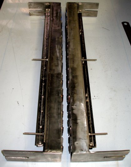
Note that the mechanical assembly should be made of a non-ferromagnetic material. We use stainless steel (AISI304). It will be clear that the excitation force can be controlled by changing the amplitude of the excitation pulses. It is quite tempting to implement this by PWM-ing the pulses at the microcode sound generation level However, there are some caveats here, in that easily audible artifacts are produced, caused by the too-low carrier frequency of the PWM signal. A cleaner approach would be using voltage- controlled current sources (using LM317 variable voltage regulators for instance) for each of the coils. However, apart from the far greater complexity of the circuitry, keep in mind that the dissipation tends to be quite high.In the string excitation diagram above, we have shown an almost sinusoidal movement. Such movement in practice will only be encountered when the excitation force from the magnets is very low as compared to the stiffness of the string. When we take the spring-behaviour of the string into account, the movement shape of the string under excitation will look more like:
Notice that the zero-cross already happens in the B phase! Also note that the curvature in the A phase depends on the distance between string and magnets, on the excitation force as well the elasticity of the string. In any case, the wave shape thus obtained will come closer to that of a real bowed string, for which a sawtooth shape is generally assumed.
The circuit for driving a single string of our <Aeio> robot looks like:
In this case the microcontroller also steers the string damper and an extra string exciter solenoid.Experiments are being conducted in using 3 separate coils driven in 3 phases, so that the rotation of the string can be controlled better and the coupling factor should become a lot higher. Furthermore, the string driver can be made movable along the length of the string. We will report on the results of these experiments in due time.
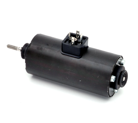
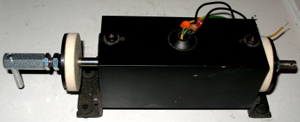
For the <Synchrochord> robot, although by design its string is plucked by a synchronous motor mechanism, we were in need of an e-bow like mechanism for the autotuning feature as we needed a resonant feedback on the string for tuning. For the string excitation we used a dismantled torque-motor. These motors are induction type AC motors with a squirrel-cage rotor. If they are made to work on single phase current, they have a shaded pole realized by a single turn copper winding in the stator. Without this they wouldn't start up. The shaded pole creates a delayed magnetic field. Types with two windings whereby one of them is phase shifted using a capacitor also exist. When the rotor is removed, the hole left makes a very suitable magnetic field for ferromagnetic string excitation if the string is passed through the hole.
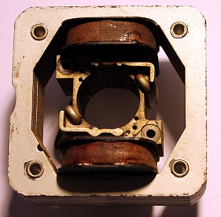
Note however that the exact center is a point of zero-force. Thus the string has to be lead through the hole a bit off center. Driving the windings of such a motor entails the design of a high voltage variable frequency power supply, not such a trivial undertaking. This is because such motors are only produced for operation on the regular power line. Details can be found in our description of the <Synchrochord> robot.Obviously the problem with the low efficiency of e-drives is not encountered when we deal with electronically amplified instruments such as electric guitars. But in this article we have very deliberately left out the possibilities of using electronic amplification. Here we intend to deal exclusively with pure acoustic sound and how to obtain it under close control.
Another use of electromagnetic drives can be found in the control of reeds in single-reed instruments (saxophones, clarinets, bagpipes). Here we do not bring the blade or reed into resonance but, on the contrary, impose our vibrational mode onto the reed. In order for this to work, the free resonant frequency of the reed must be a lot higher than the highest pitch you want to generate. This dictates the use of pretty thick spring metal reeds and as a consequence, pretty high magnetizing forces. Dual coil systems operating in two phases have proven to be the most workable and reliable. The sound color can be greatly influenced and controlled by controlling the phase angle between the currents in both coils.
Example projects:
Our attempts to realize oboe and bassoon reeds this way have not been very successful to date, but research is continuing. We can only hope flexible piezoelectric material (yes, we know of Kynar, but this material does not work here...) becomes available one day. Acoustic impedance converters (as mentioned before) have given by far the best results so far when it comes to reed-driven instruments.
A note on the phenomenon of frequency doubling and spectrum shift:
When a coil moves in the magnetic field of a permanent magnet, the coil will follow the AC input signal and thus the movement of the coil will be at the input frequency of the signal. This happens in normal loudspeakers. Likewise, if a coil is wound around a nonmoving permanent magnet, the force exerted on a ferromagnetic object in the neighborhood (string, membrane, reed, tongue...) will strictly follow the frequency and wave shape of the driving signal. This happens in the old-style telephone receivers and early headphones used for Morse telegraphy. These devices typically use a U-shaped permanent magnet with two coils connected in series, one over each leg. In front of the poles of the magnet a thin, round iron membrane is placed so that it does not make contact with the poles. However, if a non-permanent core is used for the coil (or if the core loses its magnetization...), the frequency of the force will be twice the frequency of the input signal if the ferromagnetic object on which the force is exerted it not permanently magnetized itself. Therefore a string driver like the one used in <Hurdy> must be operated electrically at half the frequency required, since the mechanism itself will operate as a frequency doubler. The same applies to membranes and reeds driven by weak iron-core solenoids.
This explains why most AC-driven buzzers designed for the mains voltage and frequency 50 Hz or 60 Hz, sound at 100 Hz or 120 Hz. Coils with permanent magnetic cores are very often used as pickup elements, for example in electric guitars, phonograph turntable cartridges and some types of contact microphones. If used as force output transducers, one has to realize that the AC voltage applied to the windings will fully demagnetize the core after a sufficient time has passed. Another perspective with relevance for sound producing devices is that you can drive a weak iron-core solenoid with a signal superimposed on a variable DC voltage. In many cases this gives you control over the spectral content of the vibrations thus produced. This is clarified in the drawing below:

It will be clear that the spectral content, both in the case of frequency doubling and in the DC-offset case described here, will contain a very large amount of very high components. If this technique is applied, it is important to realize that the spectrum will become dependent on amplitude as well. We have applied it to good effect in our robots <So>, <Bono>, <Korn> and <Autosax>.Often one will be compelled to drive the coils with square waves. Most of the time they will make use of PWM, but that aspect is not immediately relevant in this context. There is a pitfall in this case, which is shown in the upper drawing below:
If a bipolar square wave is used to drive a coil, the force exerted by the electromagnet thus formed will tend to be continuous! (Of course, due to the time required to build up a NS magnetic field followed by the buildup of an inversely polarized SN magnetic field, there will be a ripple in the force curve proportional to RL as well as to core material constants). This way it will be impossible to excite an object with a given frequency (apart from harmonics that will be produced as a consequence of finite magnetization time - the magnetic poles have to invert at the frequency of the signal, causing slow slopes on the force square wave and thus many spectral components and artifacts enter into the game). The square wave bipolar AC drive will lead to a nearly constant force with ripple on the object. This will cause high dissipation in the core material, leading to a very strong heating up of the assembly. However, if the core is a permanent magnet, this force will follow the frequency. In that case it will fluctuate up and down around the constant force of the permanent magnetic field. With a unipolar square wave drive, the force will follow the frequency of the driving voltage. If in that case (lower drawing) a permanent magnet is used as the core material, the force will either vary between the constant force of the magnet and the extra force added by the drive (if the polarity of the driving voltage corresponds the the polarity of the magnet), or else between the constant force of the magnet and the opposing and smaller force caused by the inverse polarization of the driving voltage. It follows that if permanent magnets are used as core material, correct poling of the excitation voltage becomes very important. In fact, in mechanical terms electromagnets behave a bit like diodes or rectifiers in pure electronics. A word or warning though: if you use PWM with a high frequency with substantial power on permanent magnet cores, demagnetization is likely to happen at a pretty fast rate. For those amongst you that remember that technology: it's like erasing heads on analog tape recorders... So if you really need it, it might be better to go for regular solenoids driven with a (variable) DC offset current. It can be done either by using coils with separate windings or else as shown below.
A note on solenoids and electromagnets and their freewheeling diodes:
Invariably one will see circuits where over each inductive load, a diode is placed. This diode shorts the back-EMF generated by the inductance when it goes from the on to the off state. The voltage spike produced can reach values up to about tenfold the operating voltage of the inductor. At switch off, the diode causes this voltage to drop with a current flowing through the inductor, thus extending its activation time. In practical terms: it slows down the action of the solenoid or inductor. So if you want the fastest possible response from an inductive device, it would be better to avoid freewheel diodes altogether. It is in fact possible to go without them, on the condition that the driving MOSFET or IGBT is capable of withstanding 10 times the voltage used to switch the load. Also, it must have an internal protection diode.
The back EMF generated by an electromagnet when it is switched off, largely depends on the force it exerts on the magnetisable structure it is coupled to. If this structure can vibrate and has mechanical resonance's -as in the case of all our robots using excited vibration- the back EMF becomes highly variable as well as unpredictable. As a result, calculating good values for the snubber network, tends to become nearly impossible. The best practice is to start from a calculated guess and than perform temperature measurements on the components involved under varying operational conditions.
6.- Plucked string instruments
Here there are different possible approaches. The mechanism found in harpsichords does not lend itself very well to expression control and hence should by bypassed in the context of this survey. To implement a plectrum with precise control of the striking force (speed), a stepping motor driving a rotating plectrum may be used. If the plucking has to be repetitive (such as in mandolins), a small DC motor can be used as well. For dynamic control it then should be mounted on a motor- or softshift solenoid driven slide. Rotary solenoids can also be considered here. A type produced by Magnet-Schultz Ltd. is shown on the picture. Return springs can be added if required.
Although, as said earlier, in harpsichords and suchlike, attack control is extremely limited, in some cases it is possible to realize some range here, by modifying the instrument. If the jacks are found to be placed strictly in-line and if they all pluck to the same side of the string, the entire jack-assembly can be made to move over a traject of less than a millimeter, enough for some volume control. In our spinet robot. <Spiro> we were unable to realize this because the jacks were on alternating rows and plucked the string on alternating sides. Nevertheless we implemented velocity sensitivity in this robot. A special feature of <Spiro> is that we added a muffler mechanism. It's simply a stroke of thick and soft felt glued to a piece of wood that can be pushed against strings under the action of two softshift solenoids. This gradual control over the muffler (or lute register, as it is often called in music literature), since we use two independent solenoids, allow for all gradations between low/high side and open or muffled and even overstressed, such that a sort of vibrato even became possible.

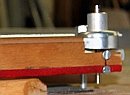
7.- Fretted instruments
If microtonality is to be implemented, linear motors are about the only reliable way to go. The linear motor moves the fret and a solenoid is used to push the string against the fret. Pulley mechanisms using stepping motors and gears lead to a lot of extra noises, comparable to those produced by now obsolete dot-matrix line printers. Also stepper motor solutions tend to behave very slowly and are inherently unprecise. But when the instrument has fixed frets, push type solenoids ought to be the first candidates. Since the force they exert on the string is a function of applied voltage, it is pretty straightforward to implement finger vibrato. This is what we implemented in our <Synchrochord> robot. The required force to push the string down on the fret in an acoustical instrument tends to be pretty large, dictating rather large solenoids. Due to their physical size, it is very difficult to implement them on smaller fretted instruments such as mandolins or ukulele's.
8.- Movement and gesture
Movement does not seem like an essential feature for expression control in musical robotics. However, we noted that exactly the fact that many components do visibly move, seems to be a major seductive element for audiences. This is not so strange, as musicians when they play do move as well. There are two distinguishable aspects to this: first there are those movements strictly related to the sound production. Beaters hitting, keys pressed down, rotating valves, the complex gestural patterns of bows on string instruments... These are most of the time easily implemented in acoustic robots but some effort at times is required from the designer to also make them clearly visible to audiences. On organs for instance, all valve movement takes place inside the windchest, normally invisible. In the <Bomi> robot, we solved this by designing a transparent windchest.
The second aspect is related to the gestures musicians do make and that are not at all required for the sound production properly speaking. One might think of them as mere theatrical, but it must be said that they contribute quite a bit to conveying musical meaning in performances. They allow listeners, through some form of embodiment, to follow musical phrasing as well as to anticipate on the course of the musical discourse. (cfr. Craenen, 2011). For such reasons, we have implemented some form of gesture in those musical robots where this seemed appropriate. Examples can be found in a few of our monophonic wind instruments:
Making the robot move, nevertheless poses often very specific problems. First of all, it is mandatory that the movement does not cause any extraneous noises. This excludes often the use of fast rotating stepping motors. The forces involved can be quite impressive. For the up and down movements in our oboe robot, <Ob>, we used a geared DC motor with a bipolar drive and a tilt sensor. The motor drives a chain to make the entire oboe assembly move. <Korn>, the robotic cornet, uses horizontal as well as vertical movement and here steppers were applied, however at the detriment of speed. The <Fa> robot, a bassoon, moves on a pivoting point on the base, driven by a DC motor and a large dented wheel segment. Here is a circuit as used for the <Fa> movement:
A full H-bridge is used to control the brushed DC motor with CW and CCW rotation. The high side MOSFET gates are driven by transformers. The PIC controller used is a 16-bit type, specifically produced for motor controls. For the <Klar> robot we used a hefty stepping motor and dented wheel gears, the instrument being mounted in a pendulum like cradle. The most advanced implementation of movement was realized in our <Asa> robot, an alto saxophone that is free to swing left-right as well as front-back. This two-axis movement was realized using two hefty bi-directional solenoids.
9.- Ultrasound applied to musical robots
When designing and building our <Tinti> robot, using tiny tintinabuli (small cast bells) shaken with bi-directional Syndyne solenoids, we were puzzled by the possibilities to apply parts of our ultrasound technology developed for our 'Invisible Instrument' to it, as we discovered that a lot of the sound spectrum of these tiny bells was indeed in the ultrasonic range. This made us add a special feature to this robot, whereby we expose the bells to a ultrasonic soundwave, controllable both in frequency and in amplitude. By then picking up the sound using two broadband ultrasonic microphones and multiplying their outputs, we can transpose the ultrasonic spectral components of the bells down to the audible range. By modulating the ultrasonic carrier frequency, we can make the tintinabuli produce sliding pitches. Obviously, here we need a loudspeaker. Details on concept and realization are available on our page on the <Tinti> robot.
This concept was driven even a step further in the realization of our automated orchestral chimes: the <Chi> robot.
Overcoming the MIDI constraints and bottlenecks
1. The 7-bit constraint
As I have mentioned in the treatment above, for most implementations of expression control, we use precise time-controlled pulses. The minimum resolution of the timers to be used is 16 bits. Now, standard midi is basically a 7-bit protocol. Thus it is impossible to offer the finest possible resolution to the user using midi. We have to remap the relevant section of the useful range into the 7-bit range offered by Midi.
The procedure for doing so starts with determining the minimum pulse width at which the valve starts opening. (tmin). For percussive instruments, you should of course take the minimum value required for the hammer to just strike the object. Next determine the shortest pulse width at which the valve fully opens and at which a further increase of pulse duration no longer makes a perceivable difference. (tmax) Note that generally these limit values will be different from device to device, and from note to note. They may also shift a bit over time due to wear of the mechanical parts. The useful timing range is now tmax-tmin. Now it would seem easy enough to just remap this range onto the 1-127 range covered by midi. Generally speaking this hardly ever leads to good results. Neither the solenoids nor our ears have linear characteristics. The mapping should be described using at least a second degree equation. To find out what curve best suits a smooth mapping of the range, we use simple curve-fitting software (Gaussfit). To get good results, one should determine some 5 intermediate points, starting with the middle of the range.
The equation found should then be implemented into the firmware of the microcontroller and here obviously one will be obliged to use lookup tables. Firstly because most microprocessors are integer math-based and secondly because modern microprocessors have more than enough memory available to store the lookups.
For ease of maintenance, we invariably implement sysex commands into our robots, allowing the experienced user to upload different lookup tables. Midi program change commands are implemented to choose between these.
2. The midi bottleneck
Midi as a protocol should now be considered outdated. This is mostly because it is way too slow to control large instrumental setups when many expression controllers have to be sent. As an alternative, preserving some compatibility, UDP/IP can be used. This topic is treated in another short article. However, MIDI is still the lingua franca for musical instrument control and therefore we have put considerable effort into using it up to its extreme limits. In our robot orchestra we have about 86 machines so far, each listening to one or two midi-channels. It will be clear that this dictates the use of a multiport midi device, our favorite (although far from perfect) being the Midiman 8x8. However, even though this gives us 128 midi channels, it means that each machine has to handle all the interrupts generated by the midiflow for many other machines. This invariably leads to glitches, lost bytes and timing problems. To overcome these it is a smart idea to build dedicated midi filters outputting only the midi data relevant for a specific machine. Here is a possible approach, using a fast dsPIC 30F3010:
The dip-switch is used to select the midi channel to be selected for pass-through. The jumper (JP1) allows you to pass the first adjacent channel as well. This was done with our quartertone automata in mind, since these use two midi channels.
A frequently occurring problem with MIDI is related to its implementation of the so called Midi-Thru ports. The ports output the incoming midi signal after passing through an optocoupler. If the signal passes through more than two of these optocouplers, signal deterioration does occur, leading to stuck notes and missing commands. A proven to be good solution to this problem is implementing midi data as RS485, so true differential. A tested and worked out proposal is described in Midi-Soup, treating midi problems more in depth.
Feedback and sensing
If the hardware is well designed, precise and reliable, it is generally better to do without any kind of force, position, pressure etc. sensing devices. Automated regulation of any parameter always comes with a price tag, not only financially, but more importantly, it is detrimental to timing precision as well as reliability. One of the most common mistakes amongst automaton builders and robot designers in the area of musical instruments is in trying to overcome deficient or poorly-built hardware by adding sensors and regulating loops in software. You invariably end up with a shaky and unreliable construction, plagued by under and overshoot. However, there are many cases in good automated instrument design where you have almost no choice. We will give a few examples, before we delve a little further into the technologies and components available.
1.- Automated rototom-playing robot: <Rotomoton>
Here we used large stepping motors to rotate the central spindle of the drums in order to tune them. As we built the robot, it turned out that the useable trajectory shifted quite a bit with the time of use. What is more, the trajectory turned out to be highly sensitive to temperature, this of course being due to the properties of the Mylar membranes on the drums. For these reasons we provided each motor-driven drum with sensors so that the beginning and end positions could be set. The microcontroller automatically adjusts the number of steps according to the signals from the sensors. First we used microswitches, but these had too much hysteresis and so we replaced them later with non-contact proximity induction sensors by Pepperl+Fuchs.
2.- Automated bass accordion : <Bako>
For this robot, the bellows are driven by a trapezoidal thread powered by a strong DC motor. In this case we needed to provide end-sensors but also a PID-regulating loop for the pressure. The rotational speed of the motor has to adapt to the air consumption, this being dependent on both the number of notes played and their pitch. In this case we used a bipolar Freescale low-pressure sensing device to measure the current air under- or overpressure inside the bellows. We could have done without the sensors and regulating loop in this case, but that would entail really huge lookup tables for all the different combinations of notes versus dynamic level. Memory constraints as well as the enormous amount of work required to fill the correct values into the lookup nudged us into the direction of a PID-regulating loop.
3.- Quartertone organ : <Qt>
In this case, we mounted two flap valves in the two windchest channels to modulate the air flow. The valves are driven by stepper motors. The problem was that we could not guarantee that when the motor stopped, the valve position would be known exactly. Therefor we mounted Melexis sensors onto the valve axis, such that the current position of the valves could be read by the microprocessor at any time. This made it possible to use the valves as reliable expression controls on the organ.
4.- Robotic cornet: <Korn>
This musical robot was designed to have movement along two axes, horizontal and vertical. A very strong stepping motor with a dented belt was used for horizontal movement. Horizontal movement is limited to 180 degrees. At first we had microswitches to sense the extremities. These were very troublesome, because the heavy mass of the instrument caused a lot of inertia leading to widely shifting end position determination as well as serious problems in debouncing the switches. Replacement of the microswitches by inductive proximity sensors did not cure all our problems. The problems with bouncing led us to use these proximity sensors as pure analog devices. Since most PIC microcontrollers have plenty of pins available that can be configured as 8 or 10-bit analogue inputs, there is no penalty in increased hardware complexity. 8-bit resolutions are more than enough if it comes to endpoint approach detection. Using analogue readouts from these sensors, it became possible to control the motor such that it decelerates smoothly as the sensor is approached. The Pepperl+Fuchs NAMUR sensors work nicely on 5V power and start changing their analogue output at distances of approx. 6 mm, even though they are rated for a 2 mm trajectory only. With these sensors fully implemented into the firmware, we got <Korn> to move quickly and smoothly.
5.- Robotic oboe: <Ob>
This robot was mounted in a cradle so that it could move in a vertical plane over an angle of about 100 degrees. The movement is driven by a geared DC motor controlled by a bipolar power driver. A chain connects the motor with the rotating axle around which the oboe is allowed to pivot. Steering the motor reliably has proved to be highly complicated because the required motor force depends on the tilt position of the instrument as well as on the direction of the movement. Here we solved the problems by using an analogue tilt sensor by Penny+Giles (type STT280/60/P2), mounted on the instrument and read by the PIC microcontroller.
6.- Robotic clarinet: <Klar>
Here again, a cradle was used to suspend the instrument such that it can swing in a pendulum like fashion. A stepping motor and a Penny & Giles tilt sensor are used for positioning the instrument. The movement angle is limited by the holding torque of the motor.
As can be seen from the examples, the PID-regulating loop with sensors was always added because of inherent problems with the electromechanical devices (slip on stepper motors, temperature changes) or limitations of the microcontrollers. This is not to say that we would tend to reject autoregulation, but only that this technology should not be called upon until all other possibilities have been exhausted.
The latest design of our piano Vorsetzer is a good example of a candidate for autoregulation. The existing model, baptized <pp2> works to a high degree of perfection, but... it needs specific lookup tables for each grand piano on which you want to use it. Pianos do show great variation in dynamic range, in touch-mapping on loudness as well as in key stiffness and repetition speed. To automate the generation of lookup tables, we started a project allowing the Vorsetzer-piano to become self-regulating. As sensors we use a normal acoustic microphone, to measure the sound output versus key-force input combined with a measurement of the counter-inductive voltage generated over the solenoids when activated. Our experiments have shown that this induction spike (normally always damped with a diode) depends to a certain extent on the mechanical resistance the anchor meets when pushing a key down. Thus it is related to the 'touch' of the piano. In this project, automation is used prior to the actual concert, exactly as is the case with a human professional pianist, who will also insist on trying out a piano prior to a public concert.
Under no circumstances would we use this technology to control the piano in the course of a performance, because the time required for the regulating loops to adjust well enough in real time would make the Vorsetzer sound very sluggish rather than responsive.
[To be completed...]
Power supplies
At first sight it may not be the appropriate place in this text to talk about power supplies. And indeed, there would be no need to even talk about them if it weren't that these 'trivial' components found in just about any electronic design, didn't cause us lots of trouble. If you are in need for a computer power supply, no problem: the market offers plenty of choices in switch mode power supplies, ranging from very low 1W power up to 1kW and more. These ready-made building blocks actually perform pretty well under the conditions they are designed for. However, if you want to use then as power source for fast switching solenoids or motors you are guaranteed to land in the space of trouble. If you take an SMPS rated for 20 A at 24 V and you use it to switch a (clamped) inductive load of 10A at a rate of say 10Hz, you are asking for trouble and guaranteed to meet it. The power supply will start oscillating or simply give up, if you do not get smoke stacks coming out and see them go to electronics heaven. Analog or linear power supplies reenter the world here, but confront us with many problems as well. Off the shelve linear power supplies capable of delivering current of 20 A and higher are almost unfindable on the market. For low currents, up to 3 A, low drop linear regulator chips come in very handy although the range of possible output voltages forms a limitation, standard voltages being limited to 3.3 V, 5V, 12 V, 24 V mostly.
The first question to ask whenever we are in need of a hefty power supply for use in robotic instruments is whether or not voltage stability is important. For driving stepping motors for instance, this is in general not important as they are basically current driven. Often an 80 V / 6 A power supply will be mandatory, but in this case we can go with the simplest of all possible designs: a transformer, a bridge rectifier and a very large electrolytic capacitor (at least 2200uF per ampere of current). This recipe in general also applies to those robots where pulse currents of variable duration's are to be delivered to solenoids. If the buffer capacitors are large enough, there will be no observable imprecision in the attack velocities.
For hold-voltages (such as in player piano's, in damper mechanisms etc.) we found that stabilization of the supply voltage is a requirement. In such case and as long as the required voltage is below 27 V, we can use the TL108x series regulators switched in parallel. For each 5 A, we need to add a regulator in parallel. The circuit requires bulky heatsinks such that it will end up being about twice as large and eighth times as heavy, as a comparable SPMS supply.
Examples:
1. Power supply for the dampers in the clamped rod robot <Rodo> (25 A/ 12 V)
Sometimes a high voltage DC power supply is required. The range of available of the shelve transformers is limited nowadays. So a TRIAC controlled power supply with a microprocessor for voltage regulation may be considered. Circuits we developed can be found on the webpage for our <Per> robot. If one takes special caution to safety, designs not using a transformer at all are very well possible.
Software and firmware for automated musical instruments
From the late eighties until about 1995 we controlled each of our robots with a different laptop computer. In that period all PCs had a printer port conforming to the Centronics protocol and we used this to control all the hardware in each robot. For automata requiring very precise timing control, such as velocity control on percussion-type instruments, or fast PWM as required for motor control, we used this parallel bus to program a cascade of dedicated programmable timer chips (Intel 82C54 type). This easily allowed us to obtain a timing resolution of 1 microsecond and even 100ns if running of a 10MHz clock. Although we used microcontrollers in many projects, in those days they were simply not fast enough to handle and parse the incoming MIDI data streams reliably.
Even today, this solution in which programmable hardware timers are used to generate each timed pulse and also for periodic signals cannot be surpassed by simple microcontroller solutions. The reason is that the indispensable interrupt mechanism required to handle the incoming data stream (MIDI commands) causes a timing jitter of at least about 60 clock cycles of the processor. If the data stream flows in at a neck-and-neck pace (that is every 0.32 ms) we end up with 1875000 'lost' clock cycles a second. For a modern 8-bit microcontroller clocked at 40 MHz, that is about 5% of its capacity. Taking into account the time required to handle the data parsing, we quickly use up about half of the total available clock cycles. As a result, the best possible timing resolution for pulses will be in the order of 20 µs, or 20 to 200 times worse than what can be achieved with hardware timers. However, the hardware timer solution requires a lot of board space and also has problems because some kind of data bus has to be implemented. When many timers are involved, the physical size of the databus limits its maximum speed.
Nevertheless, since the picture of solutions using microcontrollers has changed since the beginning of the 21st century, almost all our new automata now make extensive use of many Microchip PIC microcontrollers, despite the timing precision constraints. Our favorite types are the 18F2520, 18F2525 (28 pins), 18F4620 (40 pins), dsPIC 30F3010 (28 pins) and the 24EP128MC202 (28 pins). Using the MPLAB software provided for free by Microchip, the chips can be programmed in assembly language or in C. Using the Proton+ compiler under MPLAB it is also possible to write the firmware in Basic. (A free version of this excellent compiler is available under the name Amicus Compiler, but it is limited to the 18D25K20 PIC chip). The Proton Compiler is, in our opinion, the best on the market for now. It supports most Microchip processors.
The first thing to be done is to write a MIDI parser based on an interrupt driven UART. A circular buffer must be implemented in this interrupt handler, since the UART hardware buffer in the chips is only 2 bytes large. It is -with the processors considered here- impossible to handle MIDI input streams on a polling base without missing bytes.
Here is the code for the interrupt handler as used on the 18Fxx chips:
High_Int_Sub_Start
High_Prior_Interrupt:

    If PIR1bits_RCIF = 1 Then                            ' Was it a USART1 byte Receive that triggered the interrupt ?
        Movlw 6                                          ' Yes. So Mask out unwanted bits
        Andwf RCSTA,w                                    ' Check for errors
        Bnz _Uart_Error                                  ' Was either error status bit set?
        USART_FSR1_Save = USART_FSR1                     ' Save FSR1L\H registers
        Inc USART_IndexIn                                ' Move up the buffer
        If USART_IndexIn >= USART_BufferSize Then        ' End of buffer reached ?
           Clear USART_IndexIn                           ' Yes. So clear _USART_IndexIn
        EndIf
        USART_FSR1 = VarPtr USART_RingBuffer             ' Point FSR1L\H to _USART_RingBuffer
        USART_FSR1 = USART_FSR1 + USART_IndexIn          ' Add the buffer position to FSR1L\H
        INDF1 = RCREG                                    ' Place the received character into the buffer
        USART_FSR1 = USART_FSR1_Save                     ' Restore FSR1L\H registers
        Retfie
_Uart_Error:
        Clear RCSTAbits_CREN                             ' Clear receiver status
        Set RCSTAbits_CREN
        Retfie
    Endif
_Timer0_IRQ:
     If INTCONbits_T0IF =1 Then
        Clear INTCONbits_T0IF 					         ' Clear the Timer0 Overflow flag
        Inc Cnt.HighWord
    EndIf
    Retfie
High_Int_Sub_End
The buffer (about 100 bytes is enough, since that covers an average of 30 MIDI commands) should be allocated in protected RAM in upper memory. The mechanism makes use of read and write pointers to access this buffer. If the buffer fills up, we have to deal with a latency of roughly 30ms, about the maximum that is tolerable for real time applications.Since timing is very critical in the kind of applications we are dealing with here, we have set up a second high-priority interrupt for one of the timers. Although most PIC controllers in this series have 4 built-in timers, you have to be careful in the selection since some of them are used by the built-in PWM generators. Timer0 is the best choice as it can be programmed with a /256 prescaler. All built-in timers are only 16 bit wide. In order to get a much wider range for velocity control in automata and also to make it possible to handle all sorts of slower periodic events (vibrato mechanisms and shakers are a good example), we use the timer interrupt to increment the high word in a dword variable used as a 32-bit counter. The lowword is a copy of the timer value itself. There is an obvious penalty in doing this, as these microcontrollers are 8-bit oriented and therefore each handling of a dword requires at least 4 clock cycles.
The midi parser reads incoming data from the circular buffer and filters out all commands implemented for the robot. Here is an example of the coding:
        Midi_Parse:
            If Bytein > Pitchbend_Status Then
                If Bytein > 253 Then       '254 = midiclock, 255= reset or no byte in buffer
                                           'midiclock can interrupt all other msg's...
                                           '255 had to be intercepted since thats what we  get when no new byte flows in
                    GoTo Midi_Parse_End    'throw away...
                Else
                    Clear statusbyte       'reset the status byte
                    GoTo Midi_Parse_End    'throw away
                End If
            EndIf
            If Bytein > 127 Then           'status byte received, bit 7 is set
                Clear statusbyte           'if on another channel, the statusbyte needs a reset
                Select Bytein              'eqv to Select case ByteIn
                       Case NoteOff_Status
                            statusbyte = Bytein
                            set noteUit    'reset value 255. Cannot be 0 !!!
                            set release    '0 is a valid midi note!
                       Case NoteOn_Status
                            statusbyte = Bytein
                            set noteAan
                            set velo
                       Case Keypres_Status
                            statusbyte = Bytein
                            set notePres
                            set pres
                       Case Control_Status
                            statusbyte = Bytein
                            set Ctrl
                            set value
                       Case ProgChange_Status
                            statusbyte = Bytein
                            set prog
                       Case Aftertouch_Status
                            statusbyte = Bytein
                            set aft
                       Case Pitchbend_Status
                            statusbyte = Bytein
                            set pblsb
                            set pbmsb
                End Select
            Else                                    'midi byte is 7 bits
                Select Case statusbyte
                       Case 0                       'not a message for this channel
                            GoTo Midi_Parse_End     'disregard
                       Case NoteOff_Status
                            If noteUit = 255 Then
                                noteUit = Bytein
                            Else
                                release = Bytein     'message complete, so we can do the action...
                                If Notes[noteUit] > 0 Then
                                    GoSub NoteOff    'do the required action
                                Else
                                    set noteUit      'reset , no action
                                End If
                            EndIf
                       Case NoteOn_Status
                            If noteAan = 255 Then
                                noteAan = Bytein
                            Else
                                velo = Bytein
                                Select Case Notes[noteAan]      'check the look-up for functionality
                                       Case NoNote              ' = 0, disregard: not implemented note
                                           set noteAan          ' reset the note
                                       Case OnOff               ' =1,  case note on/off only, no pulse
                                           GoSub NoteOn
                                       Case Pulsing
                                           GoSub NotePulse      ' =2 , pulse only
                                End Select
                            EndIf
                       Case Keypres_Status
                            If notePres = 255 Then
                                notePres = Bytein
                            Else
                                pres = Bytein
                                GoSub KeyPres
                            EndIf
                       Case Control_Status
                            If Ctrl = 255 Then
                                Ctrl = Bytein
                            Else
                                value = Bytein
                                GoSub Controller
                            EndIf
                       Case ProgChange_Status
                            If prog = 255 Then                'single byte message
                                 prog = Bytein
                                 GoSub ProgChange
                            EndIf
                       Case Aftertouch_Status
                            If aft = 255 Then                 'single byte message
                                 aft = Bytein
                                 GoSub Aftertouch
                            EndIf
                       Case Pitchbend_Status                  'two bytes message
                            If pblsb = 255 Then
                                  pblsb = Bytein
                            Else
                                  pbmsb = Bytein
                                  GoSub Pitchbend
                            End If
                End Select
            EndIf
        Midi_Parse_End:                                     'jump out of parser label
The 8 and 16 bit PIC controllers are very simple microprocessors and therefore do not have multitasking, let alone multithreading, implemented. This forces us to set up a multitasking system of our own. To this purpose we also use the 32-bit hardware timer described before. By examining the time counter, tasks can be scheduled with adequate precision. The critical issue is to spread code - in particular if any serious math is involved - over as many tasks as is practical. If this rule is not observed in coding, the automaton will suffer considerably from timing jitter.
Fully documented generic source code is available on request. Many of our webpages devoted to our robots also contain links to the complete source code for the firmware driving them. We do not insert it here, for there are frequent updates and every robot has its own variations on the basic firmware. Also, the details of the code depend quite a bit on the type of PIC processor that should run it. As a general rule, we avoid loading too many tasks and functions into any single controller even though there is plenty of RAM available. We prefer to use many processors running in parallel and each with a very small subset of tasks to perform. One of the many advantages of this approach is that when a failure occurs (6), generally only a small section of the robot becomes nonfunctional.
Notes:
(1) Fairly complete catalogue of all our automated and other instruments.
(2) Composers' guide to the M&M robot orchestra
(3) More texts by the author with regard to robotics and sensors
(4) Software utility for the calculation of conical and flat valves (link to the source code). The compiled program (compiled with the PowerBasic Console compiler) is here, and requires our maths library g_indep.dll
(5) This survey only deals with the mechanics and control of expressive possibilities in automata: the expressive use of such automata in music is a completely different story. That story is told in part in my composition teaching, my lectures, my composition software projects (GMT) and in my articles on sensor technologies used to translate the expressive properties of human gesture into data that can be used to control automata and other sound-generating devices.
(6) Needless to say, the firmware should be properly debugged and tested before any automaton is passed into the hands of users and composers. Nevertheless failures unrelated to simple bugs do occur every so often. The most common failure we have encountered is latch-up conditions on the part of the PIC controllers. A complete separation of the power supply for the controllers from any controlled circuitry and attached devices seems to be mandatory. VDRs as well as protection diodes on all input pins carrying signals from remote sensors or circuitry seem to help out as well (Ellison, 2009). Earth returns have to have as low resistance and impedance as possible. To achieve this we often use 3 mm-thick red copper bars for common earth connections
This survey was first written and published in 1987. It undergoes continuous updates as our research and experience in this area expands and progresses. Feel free to reference it, but please always link to the original source.
Credits & Acknowledgments:
The firmware for a few of the Microchip PIC based controllers in the robots and automata described here was developed in close collaboration with the engineer Johannes Taelman. The MPLAB platform, provided by Microchip, was used.
Many experiments on electromagnetic devices have been carried out with the assistance of Ph.D. student Troy Rogers. Shaking devices were researched in collaboration with Ph.D. student Laura Maes.
Part of the research results presented here were obtained thanks to the support of the Hogeschool Ghent, School of Arts, where I have been employed up to 2014 as a full- time postdoctoral researcher, paid 70% of a normal wage however. Now the research goes on under the auspices of both the Orpheus Institute and Ghent State University.
Thanks to the Logos Foundation, up to 2016 funded by the Flemish Government, where my instrument building workshop and electronic research lab are based. They also provide me with all the facilities to bring this research to artistic and presentable results. Since 2017 Logos Foundation lost all it's funding due to corruption in the advisory boards and thus all research is now paid for by the author solely.
Manufacturers of electromechanical devices discussed here:
- August Laukhuff Gmbh [stopped in 2021]
- Heuss Gmbh
- Kuhnke Gmbh
- Tremba Gmbh
- Lucas Ledex, now: Saia Burgess: http://www.saia-burgess.com
- Black Knight Ltd.
- Emessem Solenoid Company Ltd. , now: Magnet-Schultz Ltd. e-mail: sales@emessem-solenoid.co.uk.
- Algoet Veren NV: this is the factory where we have our springs made to our specifications.
- Sowter Transformers Ltd. This is where we have our custom power transformers wound.
- Oxford Transformers Ltd. (Line level audio transformers)
- Italvibras (vibratory motors) http://www.vibtec.com. e-mail: sales@vibtec.com
- Pyleaudio (compression drivers): http://www.pyleaudio.com
- Lanoye Bvba: custom-made mills for the construction of conical valve seatings
- Penny+Giles, tilt sensors: +44(0)1202409409.
- Pepperl+Fuchs, inductive proximity sensors.
- Siemens, Sinamics motor controllers
Software Packages used for robot development and testing:
- MPLAB (Microchip)
- Positron Compiler (both 8 and 16 bit processors)
- PowerBasic Windows Compiler
- PowerBasic Console Compiler
- PD
- Windows 11 (Microsoft)
- GMT (Logos Foundation)
- Sonar / Cakewalk (Twelve Tone Systems)
Bibliographical references:BENADE, Arthur H., "Fundamentals of Musical Acoustics", 2nd edition, ed. Dover Publications Inc, New York,1990 [ISBN 0-486-26484-x]
BOWERS, David Q., "Encyclopedia of automatic musical instruments", Vestal Press, New York, 1972 [ISBN 0-911572-08-2]
BROOKS, Rodney A., "Flesh and Machines. How Robots Will Change Us", ed. Pantheon Books, NY 2002
BUCHNER, Alexander "Mechanical Musical Instruments", ed.Greenwood Press, Westport, Connecticut, 1978. [ISBN 0-313-20440-3]COURANT Richard and FRIEDRICHS, Kurt Otto "Supersonic Flow and Shock Waves", ed. Springer-Verlag, NY 1999. [ISBN 0-387-90232-5]
CRAENEN, Paul "Gecomponeerde uitvoerders", Ph.D.Thesis, Leiden University, 2011
DUFFIN, William John, "Electricity and Magnetism", ed. W.J.Duffin Publishing, Cottingham East Yorkshire, 2001. [ISBN 0-9510438-1-1]
ELLISON, Cliff, "Latch-Up Protection For MOSFET Drivers", Microchip application note AN763, 2009 [web]
HAYT, William H. "Engineering Electromagnetics", ed. McGraw-Hill Inc, Tokyo, 1974 [ISBN 0-07-027390-1]
MAES, Laura, RAES, Godfried-Willem, ROGERS, Troy "The Man and Machine Robot Orchestra at Logos", in: Computer Music Journal, Vol.35,nr.4, Winter 2011, p.28-48.
ORD-HUME, Arthur W.J.G, "Barrel Organ", ed. George Allen & Unwin, London,1978 [ISBN 004789005-3]
RAES, Godfried-Willem, "Bomi, an experimental organ with advanced expressive possibilities", Paper, ed. ARIP, Ghent, march 2011
RAES, Godfried-Willem, "Logos @ 50, het kloppend hart van de avant-gardemuziek in Vlaanderen", book, ed. Stichting Kunstboek, Oostkamp 2018, 224 blz.
TRIMPIN, Gerhard, "Contraptions for Art and Sound", ed. Univ. of Washington Press, 2011 [ISBN 978-0-295-99109-2]
VAN DIJK, Marian (ed.), "Robots love Music", ed. Museum Speelklok, Utrecht 2018
Last revision: November 12th, 2025.