 |
Two bits on each microcontroller for the steppers are used to read the
start and end position of the tending mechanism, two bits for each drum.
Miniature microswitches were first used as sensors. These may be replaced
by optical or inductive proximity sensors with 0.01mm resolution later
on, since our microswitches suffer from a larger than necessary hysteresis.
In 2007 we experimented with inductive proximity sensors from Pepperl+Fuchs.
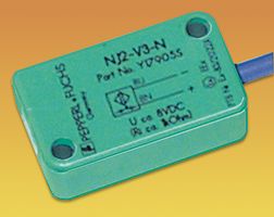 Herewith we could obtain a hysteris of ca. 30µm. The sensors are
now connected to two analog inputs on the PIC. For precize positioning,
it is mandatory to reset all motors first to the lowest and next to the
highest end position prior to running music compositions. This calibrates
the pitch range for each drum. Software to handle this automatically has
been integrated into our <GMT> language (also part of our GMT midi-file
player for the M&M robot orchestra). Technical exploded drawing showing
the construction of the tuning mechanism driven by the stepping motors:
Herewith we could obtain a hysteris of ca. 30µm. The sensors are
now connected to two analog inputs on the PIC. For precize positioning,
it is mandatory to reset all motors first to the lowest and next to the
highest end position prior to running music compositions. This calibrates
the pitch range for each drum. Software to handle this automatically has
been integrated into our <GMT> language (also part of our GMT midi-file
player for the M&M robot orchestra). Technical exploded drawing showing
the construction of the tuning mechanism driven by the stepping motors:
5. The power supply for this instrument is rated for 1130Watts. Three
transformers are used: 230V/12V - 630VA and 230V/2x35V 200VA. and 230V/24V
- 300VA. During normal operation however, power consumption is reduced
to ca. 150VA.
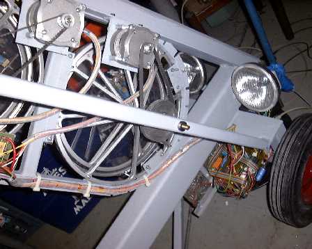
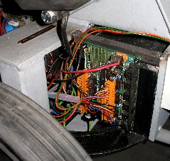
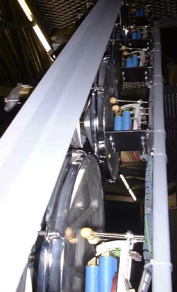
As other instruments belonging to this <Slag-Werk> project (a range
of robotic percussion instruments), this one also is designed for mobile
use and thus mounted on sturdy steerable wheels, the back of which can
be seen on the picture.
Midi implementation
and music:
If you are using <GMT> under Power Basic, you can use all specific
hardware control functions and procedures provided in our libraries. However,
direct midi control is also possible from any decent sequencer. (We use
Cakewalk or Sonar, written by Twelve Tone Systems). The midi and hardware
mapping of the different components of <Rotomoton> is:
- Solenoid beaters ( from low to high rototom):
- Drum 1: notes 48, 49, 50 (beaters from center to rim), velocity
implemented.
- Drum 2: notes 51, 52, 53, with velocity
- Drum 3: notes 54, 55, with velocity
- Drum 4: notes 56, 57, with velocity
- Drum 5: notes 58, 59, with velocity
- Lights:Bright white carlights: notes 114, 115 (the velo-byte controls
the light strength)
- Light: Blue LED sportlight, frontal forward orientation: Note 116
(on/off only)
- Light: Blue LED spotlight, frontal oriented towards drums: note117.
(on/off only)
- Lights: Notes 118-119: reserved for future expansion. (on/off only)
- in music staff notation:
- for drum rolls: [only implemented under GMT
and thru our midi file player]
Note on followed by note pressure. The repeat
frequency (in Hz) will be: (0.1 + 30 * aftertouchvalue / 127 ) for the
highest three drums; (0.1 + 25 * value / 127) for the lowest two. The
velocity can be changed during the drum roll by sending a note on with
a different velocity. The drum roll continues until a note off for that
note is received.
- Drum 1: note 48 + pressure
- Drum 2: note 51+ pressure
- Drum 3: note 54 + pressure
- Drum 4: note 56 + pressure
- Drum 5: note 58 + pressure
- Stepping motors:
You can tune the drums individually by sending controllers 101 to 105
(from low to high). Note that the absolute pitch is very difficult to
control, since it depends highly on the initial and manual tuning of
the drums.
- Drum 1: controller 101, values 1 - 127 mapped over a fourth (range
set by calibration commands)
- Drum 2: controller 102, values 1 - 127 mapped over a fourth
- Drum 3: controller 103, values 1 - 127 mapped over a minor sixth
- Drum 4: controller 104, values 1 - 127 mapped over a major sixth
- Drum 5: controller 105, values 1- 127 mapped over an octave +
minor third.
- Callibration commands (these command cause the range to be recalculated
internally):
- Reset Drum 1 to lowest position: controller 81: value > 0 - value
= %False = cancel command
- Reset Drum 2 to lowest position: controller 82: value > 0
- Reset Drum 3 to lowest position: controller 83: id.
- Reset Drum 4 to lowest position: controller 84: id.
- Reset Drum 5 to lowest position: controller 85: id.
- Set Drum 1 to Highest position: controller 91: id.
- Set Drum 2 to highest position: controller 92: id
- Set Drum 3 to highest position: controller 93: id
- Set Drum 4 to highest position: controller 94: id
- Set Drum 5 to highest position: controller 95: id
- Calibrate range drum 1: controller 111: id.
(after calibration the drum will be at the mid-position)
- Calibrate range drum 2: controller 112: id.
- Calibrate range drum 3: controller 113: id
- Calibrate range drum 4: controller 114: id
- Calibrate range drum 5: controller 115: id.
- Beater power on/off: Controller 66 (on/off)
- Motor power on/off: Controller 65 (on/off). This command also initiates
a calibration command on all five drums, at the end of which all drums
will be tune to the midi midrange position (64). So you do not have
to send any of the above calibration commands.
- Lights:
- notes 114, 115 (large white carlites), velo controls the dimming,
- notes 116, 117 (blue LED spotlites in the front) (on/off)
Composers that wrote pieces for <Rotomoton> sofar, include: Godfried-Willem
Raes ('Rotstuk' voor Rotomoton),
Michael Manion, Moniek Darge, Kristof Lauwers, Rene Mogenson ('The swarm
breaks through the net'), Claude Coppens. Rotomoton is a fixed member
of the M&M ensemble and as such also performs in orchestra pieces
such as 'Technofaustus', 'Gestrobo', 'Picrada', 'STOvSQE4MM' , "Quadrada",
"g_tech611" .. by Godfried-Willem Raes and many other pieces.
Collaborators:
- Filip Switters (TIG welding)
- Xavier Verhelst
- Moniek Darge (painting)
- Kristof Lauwers (GMT player and software simulator implementation)
- Johannes Taelman (PIC revision 2007)
Dimensions:
- width: 1500mm
- height: 2100mm
- depth: 600mm
- weigth: 220kg
- power consumption: 1130Watts / 230V AC
- data input: midi input. (direct network UDP/IP will be added soon)
Insurance value: 19.000 €.
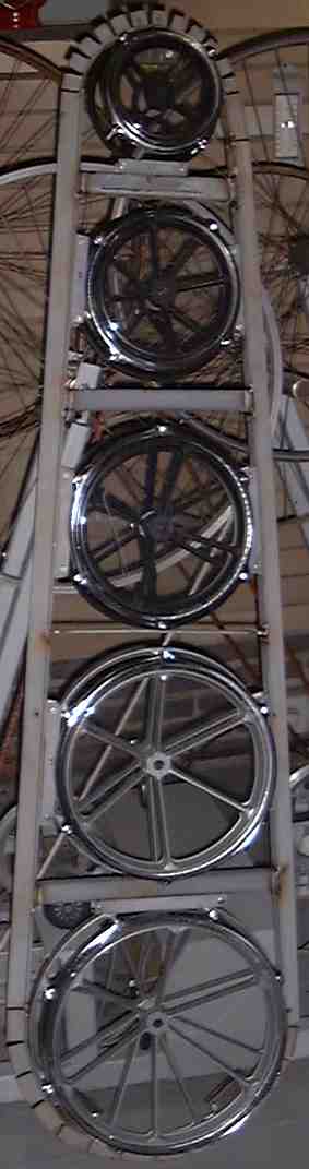
Construction of this automated instrument started august 2000 and was
completed in its first working version around easter 2001. Rotomoton played
its first scales on april 26th of 2001. It is now a permanent robot member
of the Logos <M&M> ensemble. Its hardware was completely revised
and rebuild in 2007.
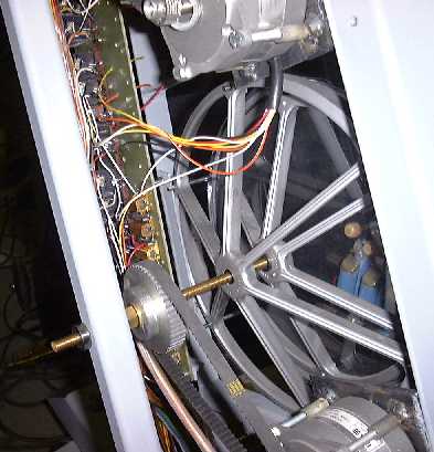
The picture on the left shows the first step in the construction of <Rotomoton>:
the assembly of the five rototoms in a TIG-welded frame.
The final instrument is shown on this picture: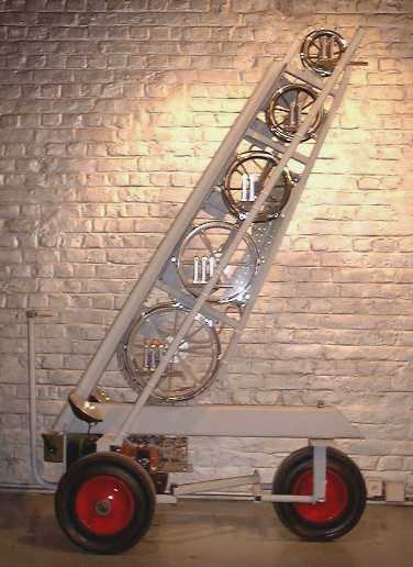
The <Rotomoton> automat can be heard on the Logos
Public Domain CD <Automaton> (LPD007).
Revisions 2005-2007:
aim:1. improving pitch change speed by increasing torque from stepping
motors.
In the original design we used unipolar steering of the stepping motors.
By using bipolar drives, the torque can be increased with a factor 4 compared
to the first version, where considerable power got lost in the series
resistors. We decided to use Intelligent Motion Systems (IMS) stepping
motor drivers, type IB106, each capable of delivering currents up to 6A
and able to cope with voltages from 24 to 80 Volts. (Cost: ca. 350 Euro/piece)
. For the motors we use in this robot, we could easily increase the power
supply voltage to 48V and thus achieve high rotational speeds with high
torque. So for each stepper, we used a single IB106 module, controlled
from a PIC (18F2525) directly. The timing requirements for the motor driver
are:
In the first design we had five microswitches to sense the lowest possible
position for the stepping motors. No sensors were foreseen for the highest
possible position. This was dictated by the fact that on a standard PC
printer port, there are only 5 bits free for input. Since we do not have
this limitation anymore using a PIC design, we now fitted rotomoton with
end position sensing microswitches as well.
aim 2: changing control such as to get rid of yet another Windows laptop,
by controlling rotomoton directly via midi commands and optionally midi
via UDP/IP.
aim 3: Increasing the dynamic range of the instrument. This involved
merely increasing the power supply voltage for the solenoid drivers to
ca. 75V. The pulse generation can be confined to a separate PIC controller.
By also using PIC microprocessors for the steppers, we could at the same
time make the robot listen to midi commands directly.
The five boards for motor control we now use were build after the following
schematic:
Some sections of the circuitry do not apply to Rotomoton, since the board
was designed such as to replace similar functions in our
<Flex> robot as well. The power supply section had to be completely
revised also. We kept the hefty 12V/630VA transformer since it was required
for the brigth lights on <Rotomoton>. In the new version dimming
becomes possible, since they use PWM on their supply voltage. Note the
absense of a smoothing capacitor on its power supply. As a whole, the
power supply is clearly overdimensioned now, since the bulbs will draw
at the most 200W of power. The solenoids for the beaters get their power
from a separate 70V ungerulated power supply using a toroidal transformer.
For the stepping motors, an extra 24V /12A transformer is connected in
series (after rectification) with the already present 12V supply. The
unstabilised voltage available for the motors thus becomes 50V. With all
motor activated this voltage may collapse to 44V.
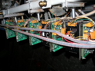
Board layout for the five motor control PIC-micro boards:
 Circuit
drawing for the beater pulse-generating boards. Circuit
drawing for the beater pulse-generating boards.
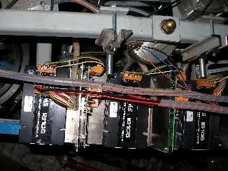
On the left picture below, we see the new five motor control boards and
next to it the new midi-hub board.
Last updated: 2017-08-05
by Godfried-Willem Raes
Maintenance, research and repair logbook:
- 01.09.2000: Start construction rotomoton.
20.09.2006: Rewiring of power supply block
21.09.2006: Tests for the new power supply sections. Beater PIC programmed.
Given the higher voltage we use now to operate the beaters, we have
to remove all surge arresters over the solenoids.
- 23.09.2006: Velo scaling tests and PIC1 debugging session.
- 25.09.2006: Return springs on beaters replaced. PIC
beaters, code version 3.0
- 27.09.2006: Start construction frontal lights assembly.
- 28.09.2006: Front lights construction and wiring finished.
Mapping on notes 116, 117. Blue LED spotlights running on 12V.
- 09.10.2006: Discussion meeting with Johannes Taelman
with regard to code implementation for the steppers and coding for the
midi-hub board.
- 10.10.2006: Midi hub board programmed: relais ctrl.66,
67. PWM for the strong lights implemented. Blue frontal lights working,
- 11.10.2006: New test code written in GMT.
- 05.12.2006: New motor control PIC boards designed.
- 11.12.2006: New PIC-micro board design send to Europrint
for production.
- 04.01.2007: New boards arrived. First test board assembled
and soldered.
- 05.01.2007: Construction stainless steel chassis parts
for the motor control boards.
- 06.01.2007: further assembly and soldering of PIC-micro
boards.
- 08.01.2007: wiring of microswitch sensors to the controller
boards.
- 10.01.2007: finalisation of wiring: power lines and
current sensing resistors. (330 Ohm). Without these the maximum current
is 6A. With 330 Ohms, we bring it down to 3.45A
- 12.01.2007: PIC-specs upgraded. Jumpers for H/F placed
parallel to 6p weidmuller, to Vcc to set full step mode.
- 13.01.2007: construction detail pictures added on this
webpage.
- 22.02.2007: Johannes Taelman contacted again for PIC
coding. Pic-specs upgraded.
- 26.02.2007: Still no news from Johannes...
- 13.03.2007: Johannes shows up. Discussion on PIC implementation
of motors.
- 18.05.2007: Programming works for the motor control
PIC's.
- 19.05.2007: wiring bug in motor Cetronic HY200 3424
170 A8 hybrid stepping motor repaired.
- 28.06.2007: PIC programming session with Johannes Taelman.
Sensor reading code and end position commands implemented.
- 30.08.2007: PIC programming works continued. Midi-out
added on boards for debugging. Reading end switches seems to work well
now.
- 31.08.2007: PICS 1 -5 for motor control reprogrammed.
Code is autocalibrating now. Command request for low pos and highpos
on init is essential now.
- 01.09.2007: GMT test code rewritten for the new functionality.
Pitch controller mapping must be in error somewhere...
- 02.09.2007: Loose wiring on highest drum motor repaired.
Further debug of test and evaluation code. Search into the origins of
the collapse and heavy load on the logic power supply. (5V). Problem
with the too high hysteresis of the microswitches.
- 03.09.2007: Due to its large size and heavy weight,
Rotomoton cannot be transported with our regular Dockx car rental trucks.
A large truck is required. Rotomoton is higher than <Krum>. All
springs on the beater solenoids replaced with pull-type springs with
eyelets 0.7 x 6.7 x 30. (Fabory assortment box). Some beaters replaced
with bakelite M5 bullet-balls.
- 04.09.2007: 12V car relais for the beater voltage burned
out. Replaced with new 30A type. Current drawn: ca. 150mA. Voltage regulator
on midi hub board (7805 type) equiped with cooling profile for small
TO220.
- 06.09.2007: New programming session for the PIC firmware.
Note order bug... Sysex implemented.
- 08.09.2007: Programming sessions with Johannes Taelman
PIC's. Electrolytic exploded on midi hub board... Component replaced
with 25V type and board cleaned thouroughly.
- 09.09.2007: Hardware debug session: the italian made
car relais apparently cannot survive long periods in the activated state.
Not only the coils get very hot and eventuially burn out, but worse
even, at doing so they cause a short between the coil driving voltage
and the relais contacts themselves. Such designs ought to be forbidden
since they contradict the reason of existence of the relais-device itself!
So we did throw the relais out altogether. They caused a new explosion
of the 1mF/25V electrolytic on the hub board. The dissipation of the
7805 regulator seemed on the high side. It got very hot, so we decided
to mount a 7810 preregulator on the midi-hub board, spreading the dissipation
equaly over two devices. Relais replaced with small Zettler types, 12V
coil, 16A contacts. Electrolytic capacitor on power input of hub board
replaced again with a new 1mF/25V specimen.
- 10.09.2007: New Rotomoton demonstrated for Kristof
Lauwers and Sebastian Bradt. PIC finalisation session with Johannes
Taelman does not happen: Johannes is sick.
- 12.09.2007: Pepperl & Fuchs proximity sensors delivered.
First evaluations and tests. The possibilties examined are drawn in
the following circuit drawing:
 The principle of operation of these inductive proximity sensors is that
they contain an LC oscillator circuit (operating frequency ca. 714kHz)
that as soon as a metalic object comes close enough, the oscillation
damps and eventually stops alltogether. The amplitude output can be
used as an analogue signal to measure the distance in a traject-range
of about 1mm corresponding to a voltage range of 1 to 2V, depending
on the resistor values taken for R11,R12. The remainders of the oscillation
signal can be greatly reduced by placing a 47nF capacitor across the
inputs to the PIC. This goes at the detriment of response speed however.
The measured hysteresis of the sensor device is ca. 3% of the range
(1mm), so ca.30 microns. Although the sensors are specified for a normal
operating voltage of 8V DC, they work fine down to ca. 3V.
The principle of operation of these inductive proximity sensors is that
they contain an LC oscillator circuit (operating frequency ca. 714kHz)
that as soon as a metalic object comes close enough, the oscillation
damps and eventually stops alltogether. The amplitude output can be
used as an analogue signal to measure the distance in a traject-range
of about 1mm corresponding to a voltage range of 1 to 2V, depending
on the resistor values taken for R11,R12. The remainders of the oscillation
signal can be greatly reduced by placing a 47nF capacitor across the
inputs to the PIC. This goes at the detriment of response speed however.
The measured hysteresis of the sensor device is ca. 3% of the range
(1mm), so ca.30 microns. Although the sensors are specified for a normal
operating voltage of 8V DC, they work fine down to ca. 3V.
- 14.09.2007: Robotic tests with sonar interface (Gestrobo
Study for Rotomoton), Picradar (Picradar Study for Rotomoton) and 2.4GHz
radar (Quadrada study 'Rotom').
- 17.09.2007: PIC programming session. Now we autocalibrate
only on the edge of the switches. Controller 111-115 also implemented
now as well as autocalibrate on controller 65. Rotomoton code in GMT
adapted according to new version.
- 25.09.2007-02.10.2007: Rotomoton tests under GMT control.
- 17.09.2007: Rotomoton part added in 'De weg,der Weg,
the way' with HY1 sensor.
- 26.10.2007: Some extra 24V solenoid valves ordered
from A.Laukhuff to add beaters on the drums.
- 31.08.2008: Upgrade of the GMT tescode for Rotomoton
- 07.06.2011: 10A fuses on the beater power supply went
off. The connectors on the pulse board need replacement as the contacts
became shaky. Solenoid 3 on the lowest drum also shows shaky behaviour...
repair session.
- 08.06.2011: Rotomoton plays in the M&M orchestra
in a piece by Rene Morgenson.
|
|

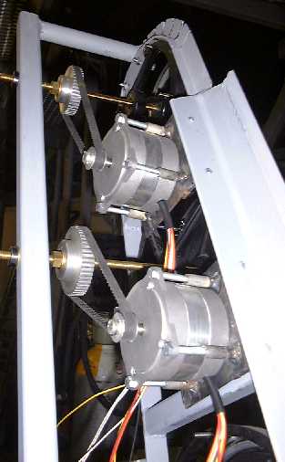
 The hybrid stepper motors used in this design are Cetronic or MAE type
HY200 3424 170 A8, specified for Umax = 90V and maximum phase current
1.7A. We use them with the motor windings in parallel.
The hybrid stepper motors used in this design are Cetronic or MAE type
HY200 3424 170 A8, specified for Umax = 90V and maximum phase current
1.7A. We use them with the motor windings in parallel.