|
<Pos>
|
|
an automated organ positive Godfried-Willem RAES 2018 |
|
<Pos>
|
|
an automated organ positive Godfried-Willem RAES 2018 |
Robot: 'Pos'
 In December 2017, out of the blue, we received an e-mail from brother Kris
Oelbrandt in a Dutch Benedictine monastery offering us a small pipe organ for
free. Of course we could not turn this down and on January 2018 we transported
the instrument to our instrument building workshop at Logos Foundation. The
organ was made by Gerard Pels in the early nineties of the 20th century, an
outstanding organ builder based in Herselt. He was born in 1955 and died in
2014. In 2017, the Pels
In December 2017, out of the blue, we received an e-mail from brother Kris
Oelbrandt in a Dutch Benedictine monastery offering us a small pipe organ for
free. Of course we could not turn this down and on January 2018 we transported
the instrument to our instrument building workshop at Logos Foundation. The
organ was made by Gerard Pels in the early nineties of the 20th century, an
outstanding organ builder based in Herselt. He was born in 1955 and died in
2014. In 2017, the Pels  organ factory itself went bankrupt and stopped activity. The original design
and order was for a tuning system using 13 notes per octave based on just intonation
intervals, an idea worked out by composer Kris Oelbrandt. Here is a link to
the document describing this tuning
system. When he entered the monastery in 2002, the organ found a use in
the religious rituals at the monastery in Zundert and to serve that purpose
it was modified and retuned by Gerard Pels to conform to 12-tone equal temperament.
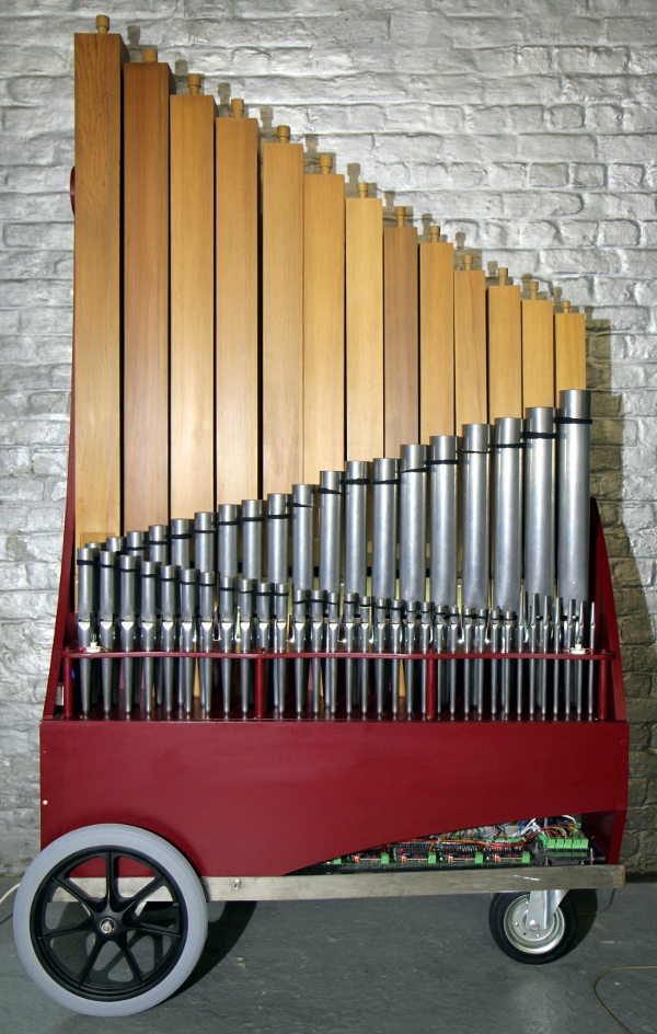
This is the organ as it arrived in our workshop: The
sizes were: depth: 335 mm, width: 1223 mm and height (including the pipes):
2210 mm. (sizes not including the keyboard, a separate component).
organ factory itself went bankrupt and stopped activity. The original design
and order was for a tuning system using 13 notes per octave based on just intonation
intervals, an idea worked out by composer Kris Oelbrandt. Here is a link to
the document describing this tuning
system. When he entered the monastery in 2002, the organ found a use in
the religious rituals at the monastery in Zundert and to serve that purpose
it was modified and retuned by Gerard Pels to conform to 12-tone equal temperament.
This is the organ as it arrived in our workshop: The
sizes were: depth: 335 mm, width: 1223 mm and height (including the pipes):
2210 mm. (sizes not including the keyboard, a separate component).
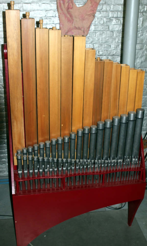
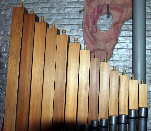
The single register (8' holpijp) was realized as follows: The lowest octave
(note 36 to 48) are stopped wood pipes placed on the back row on the wind chest,
the mid register (notes 49 to 93) are stopped tin pipes with an inverted resonator
tube mounted on the inside of the pipe stops, and the highest 7 notes (94 to
100) are open tin pipes, slightly anti-conical. The pipes are arranged in three
rows. In the windchest, solenoid driven valves are used, thus highly simplifying
the automation of the instrument by us. The keyboard was a regular 5-octave
organ keyboard with electric contacts connected to the organ through a single
multi-conductor cable. Here are some detailed pictures: 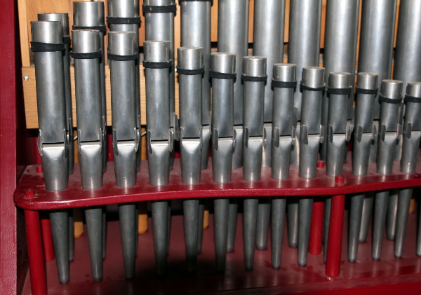
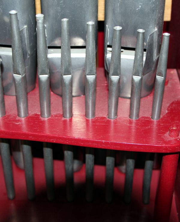
Here is a drawing of the
construction of the metal pipes, showing the internal resonator tube (inside
soldered chimneys, in the proper language of organ builders). 
Unfortunately for us, the multi-cable used no color coded wires but plain and
very thin enameled copper wire... We could figure out the wiring from measuring
and testing on the connector used to connect organ and keyboard: 
The original wiring had a common ground connection and diodes across the pallet
valve solenoids. It was wired as drawn here: 
All diodes needed to be removed and replaced with VDR's or diodes on the control
boards to make automation easy. High side mosfet switches are a lot more troublesome
to design than the usual low side switches. This is what the pallet lifting
solenoid valves inside the windchest look like:
Type 1: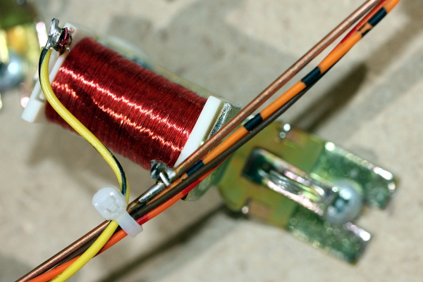
Type 2: 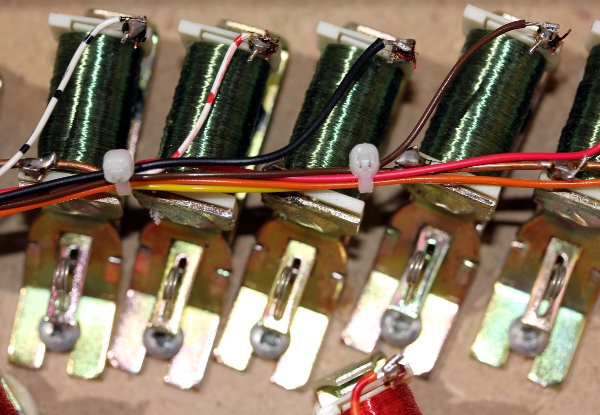 Type 3:
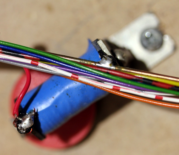
This is a picture of the original organ keyboard: 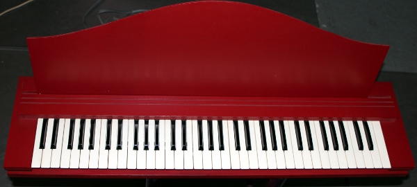 The large connector originally found a place on the backside of the case. Of
course we had no need for a keyboard, as in this project we decided to go for
a stand-alone robot. Nevertheless, it can still be played with any standard
MIDI keyboard. We rewired the complete windchest, using color coded wires to
make the final wire-up a lot easier as compared to the tiny enameled copper
wires used in the original design: :
The large connector originally found a place on the backside of the case. Of
course we had no need for a keyboard, as in this project we decided to go for
a stand-alone robot. Nevertheless, it can still be played with any standard
MIDI keyboard. We rewired the complete windchest, using color coded wires to
make the final wire-up a lot easier as compared to the tiny enameled copper
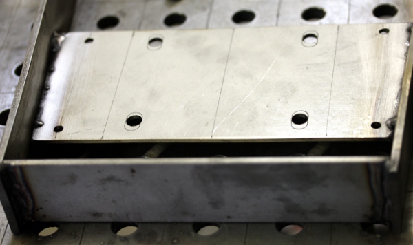
wires used in the original design: : 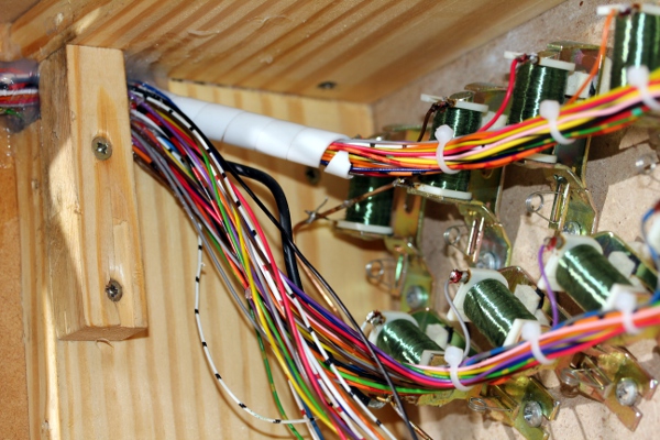 The wind, delivered by a Laukhuff Ventola 600 Pa compressor, is stabilised using
spring loaded bellow:
The wind, delivered by a Laukhuff Ventola 600 Pa compressor, is stabilised using
spring loaded bellow: 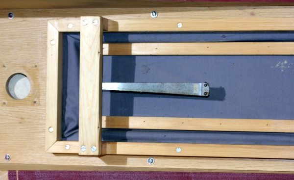 The round hole in the picture is the wind inlet from the compressor.
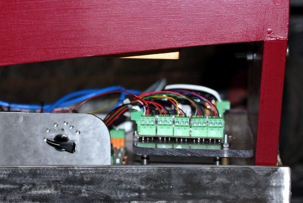
The entire circuitry for this robot makes use of five fast PIC
controllers: Microchip PIC18F4620 - I/SP types. For each group of 14 notes,
a controller takes care of the midi input parsing and the note on/offs, MOSFETS
and valve solenoids. There is precise control over the note attack (the velocity
byte accompanying each note on command controlling the response speed of the
valves). This design was more or less a direct copy of what we did for our <Bomi>
robot, although here we did not implement PWM during note hold. Key pressure
is used for note-repetition.  Thus,
here again, it is important to the user to know that the velocity byte in the
midi note-on command does not control sound volume, but only the way the pipes
speak. It is strictly an attack control. For detailed circuitry and board population,
we refer to the webpage of our <HarmO> robot our
since it uses the same boards. Here is the complete circuit for a board
serving 14 notes, showing the microprocessor port assignments. :
Thus,
here again, it is important to the user to know that the velocity byte in the
midi note-on command does not control sound volume, but only the way the pipes
speak. It is strictly an attack control. For detailed circuitry and board population,
we refer to the webpage of our <HarmO> robot our
since it uses the same boards. Here is the complete circuit for a board
serving 14 notes, showing the microprocessor port assignments. :  The
PIC firmware however is very similar to what we wrote for <Bomi>, but
here we implemented key pressure control for note repeat. The boards with components
for this circuit is shown here:
The
PIC firmware however is very similar to what we wrote for <Bomi>, but
here we implemented key pressure control for note repeat. The boards with components
for this circuit is shown here: 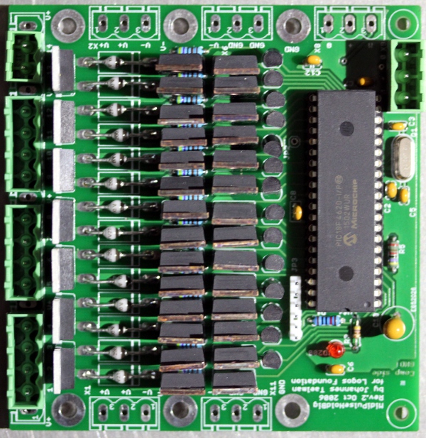 A
sixth PIC microcontroller (a 18F2525 type) takes care of the steering of the
windvalve/tremulant as well as of the motor commands and the primitive PWM for
the motor controller.
A
sixth PIC microcontroller (a 18F2525 type) takes care of the steering of the
windvalve/tremulant as well as of the motor commands and the primitive PWM for
the motor controller.
The circuit overview for the <Pos> robot looks like this:
For the motor control, we wanted to keep things as simple and
cheap as possible, avoiding to use an expensive regular 3-phase motor controller.
Thus we revisited an old and proven but quite primitive circuit principle:  This is pretty easy to implement on a PIC controller, as long as the controll
pulses are longer than a full period of the mains frequency, 20 ms and/or even
multiples of a full period. Due to the inertia of the motor and its fan rotor,
we can go with very slow pwm. Obviously it is impossible to let the motor run
at speeds higher than the nominal speed, as this would require changing the
mains frequency. The solid state AC relay we used is MP240D4, as it's a zero-cross
relay specified for 4 A at 280 V ac. The complete circuit for the MIDI parser
and hub board is this:
This is pretty easy to implement on a PIC controller, as long as the controll
pulses are longer than a full period of the mains frequency, 20 ms and/or even
multiples of a full period. Due to the inertia of the motor and its fan rotor,
we can go with very slow pwm. Obviously it is impossible to let the motor run
at speeds higher than the nominal speed, as this would require changing the
mains frequency. The solid state AC relay we used is MP240D4, as it's a zero-cross
relay specified for 4 A at 280 V ac. The complete circuit for the MIDI parser
and hub board is this: 
The firmware for all PIC microprocessors was written in Proton Basic.
|
Firmware for the midi-hub and motor board Version 1.2 - 19.05.2018
|
source code | hex-dump |
| Firmware for the pulse-hold boards | source code | hex dump board 1 |
| hex dump board 2 | ||
| hex dump board 3 | ||
| hex dump board 4 | ||
| hex dump board 5 |
Description of the organ register:
Circuit Overview:
Mapping
Midi implementation:
The midi channel for <Pos> is 2 (0-15) or 3 (1-16).
Midi note range: 36- 100., velocity implemented (steers the speed wherewith the valves do open and hence the note attack). Individual note aftertouch (polyphonic) under development.
Note Off commands are required, note release is not implemented.
Key pressure is implemented for automatic note repeats. The pressure value determines the repetition speed. Maximum repetition speed is 16Hz, but if such fast values are used, velocity values have to be kept at very low values. It is obvious that when the repetition lenght is shorter than the velocity pulse lenght, repetition will not work. Also, note that repeats using key pressure are 'sticky'. The setting is not cancelled with a note off. So, once set all new note-on commands will lead to repeated notes, unless key pressure is set to zero again.
Controllers:
Controller #7 is used for the wind pressure (motor speed). The normal setting should be 127. Default startup value in the PIC firmware is 0. It cannot be used for fast wind pressure modulation but is perfectly suitable for slow crescendo and decrescendo. Note however that the pitch as well as the intonation may be affected when <Pos> is operated on non-standard wind-pressures.
Controller #30 is used to set repetition speed for all notes to one and the same value. The parameter determines the repetition speed. (range 2Hz to 16Hz for values from 1 to 127). Repetitions start on reception of a note-on command. Thus, phase shifts of the repetition frequency will occur if notes are not started at the same time. This controller, with value 0 can also be used to cancel all repeats.
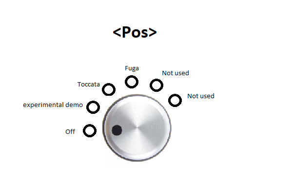
Controller #66 is used to switch the robot on or off.
The tremulant is implemented using
a large solenoid working on the bellows. Modulation speed can be set using midi
controller 1. Default value for controller 1 when using the tremulant: 64.
Controller #123: <Pos> responds to the midi all-notes-off command. This command also switches off the lights, but not the motor. To switch the motor fully off, controller 66 should be used or else controller 7 can be set to zero.
Technical specifications:
Design and construction: dr.Godfried-Willem Raes (2018)
Collaborators on the construction of this robot:
Music composed for <Pos>:
| Back to Logos-Projects page : projects.html | Back to Main Logos page:index.html | To Godfried-Willem Raes personal homepage... | To Instrument catalogue |  |
Robot: <Pos>
Voorlopig is geen Nederlandse beschrijving beschikbaar. Zolang
we geen strukturele erkenning krijgen van de Vlaamse Gemeenschap, en zolang
hoofdzakelijk korrupte poco-pomo maffiosi de ministeriele advieskommissies bevolken,
zal daar ook niet meer aan gewerkt worden.
Tessituur:
Op 13 september 2018 vertrok <Pos> voor zes maanden naar de Speelklok Museum in Utrecht. Ter gelegenheid daarvan werd hij voorzien van de mogelijkheid volkomen autonoom een aantal demo-stukken te spelen. In 2020 was <Pos> te gast op het Lunalia festival te Mechelen met de 'Musik fuer ein Floetenuhr' van Ludwig van Beethoven. In 2024 maakte <Pos> deel uit van het robotorkest in een opera produktie van de Deutsche Oper Berlin.
| Building logbook | Bouwdagboek |
| Following diary given an idea of the work involved in the making of the <Pos> robot. It also illustrates the building proces. |
Omdat ons vaak wordt gevraagd hoeveel werk en tijd kruipt in, en nodig is voor, het bouwen van dergelijke muzikale robots, houden we ook voor <Pos> een beknopt en geilllustreerd bouwdagboek bij: |
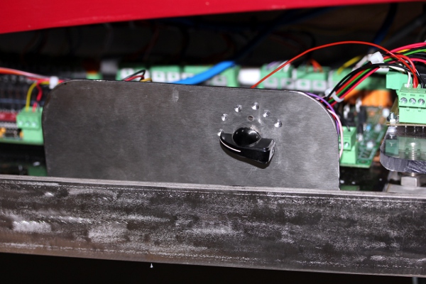
 And, as people often
did not find the on/off switch on <Pos>, here it is:
And, as people often
did not find the on/off switch on <Pos>, here it is: 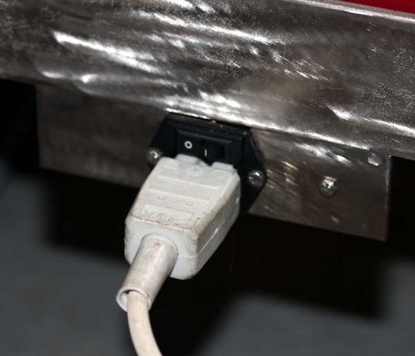
 The connections on the Axoloti
board look like this:
The connections on the Axoloti
board look like this: 
 After
replacing this board <Pos> found to work perfectly again. Some retuning
may be required, but this is unrelated to the repair just performed.
After
replacing this board <Pos> found to work perfectly again. Some retuning
may be required, but this is unrelated to the repair just performed.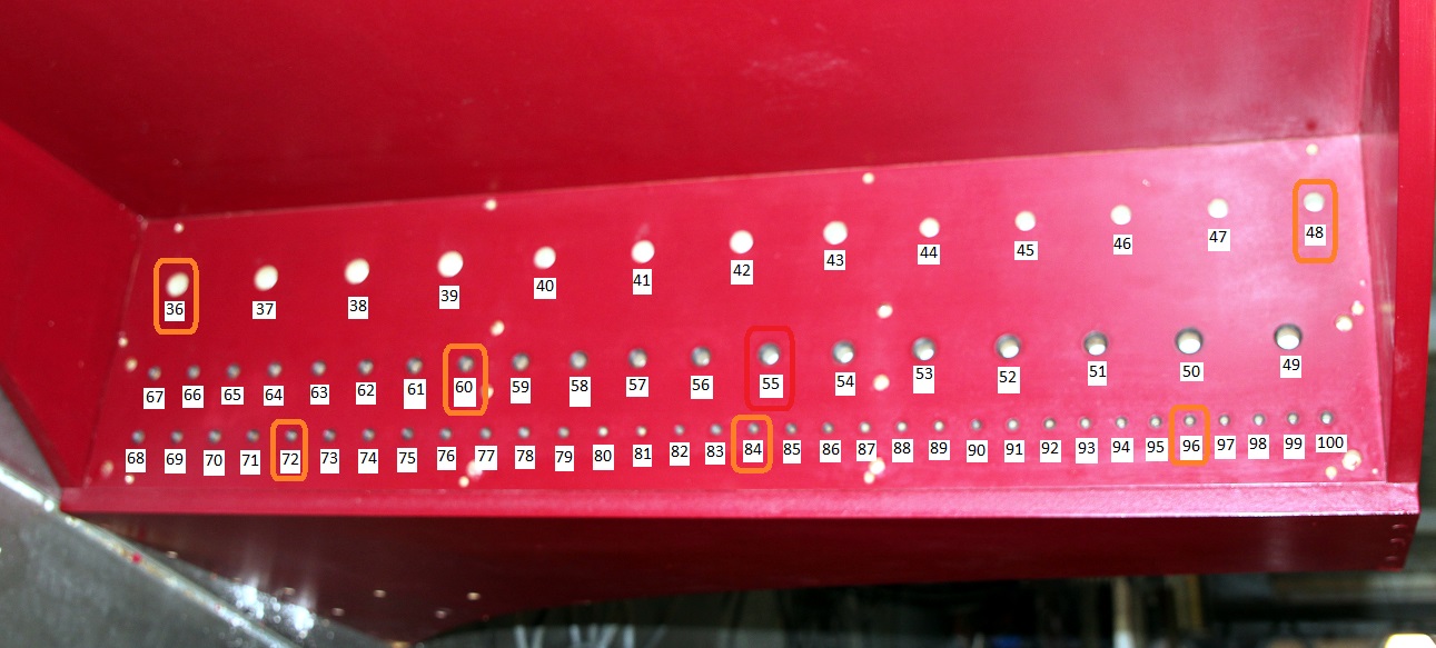 This is the relevant part of the inside of the windchest, marked with midi
note numbers:
This is the relevant part of the inside of the windchest, marked with midi
note numbers: 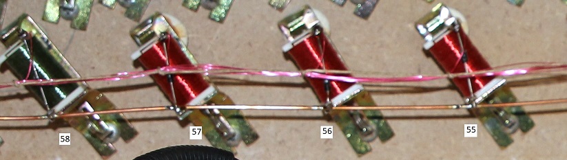
To be done
Robodies Pictures with <Pos>:
none as yet. Candidates?
| (Terug) naar logos-projekten: | Terug naar Logos' index-pagina: | Naar Godfried-Willem Raes personal homepage... | Naar katalogus instrumenten | |
Technical data sheet and maintenance instructions:
Board 1:
| board output | connector pin | mapping | wire color | remarks | PIC pin | Weidmueller |
| 1 | 2 | note 36 | black | pulse/hold | 4,3 | 4p1 |
| 2 | 3 | note 37 | brown | pulse/hold | 2,5 | 4p2 |
| 3 | 4 | note 38 | red | pulse/hold | 6,7 | 4p3 |
| 4 | 5 | note 39 | orange | pulse/hold | 8,9 | 4p4 |
| 5 | 7 |
note 40 |
yellow | pulse/hold | 10, 37 | 4p1 |
| 6 | 8 |
note 41 |
green | pulse/hold | 36, 35 | 4p2 |
| 7 | 9 | note 42 | blue | pulse/hold | 34, 33 | 4p3 |
| 8 | 10 | note 43 | purple | pulse/hold | 30, 29 | 4p4 |
| 9 | 12 | note 44 | grey | pulse/hold | 28, 27 | 4p1 |
| 10 | 13 | note 45 | white | pulse/hold | 24, 23 | 4p2 |
| 11 | 14 | note 46 | black - white | pulse/hold | 22, 21 | 4p3 |
| 12 | 15 | note 47 | red - white | pulse/hold | 15, 16 | 4p4 |
| 13 | 17 | note 48 | red - black | pulse/hold | 17, 18 | 2p1 |
| 14 | 18 | note 49 | brown | pulse/hold | 19, 20 | 2p2 |
Board 2:
| board output | connector pin | mapping | wire color | remarks | PIC pins | Weidmueller |
| 1 | 2 | note 50 | orange - red | pulse/hold | 4, 3 | 4p1 |
| 2 | 3 | note 51 | orange - black | pulse/hold | 2, 5 | 4p2 |
| 3 | 4 | note 52 | yellow - black | pulse/hold | 6, 7 | 4p3 |
| 4 | 5 | note 53 | green - yellow | pulse/hold | 8, 9 | 4p4 |
| 5 | 7 | note 54 | blue | pulse/hold | 10, 37 | 4p1 |
| 6 | 8 | note 55 | purple | pulse/hold | 36, 35 | 4p2 |
| 7 | 9 | note 56 | grey | pulse/hold | 34, 33 | 4p3 |
| 8 | 10 | note 57 | pink | pulse/hold | 30, 29 | 4p4 |
| 9 | 12 | note 58 | black | pulse/hold | 28, 27 | 4p1 |
| 10 | 13 | note 59 | brown | pulse/hold | 24, 23 | 4p2 |
| 11 | 14 | note 60 | red | pulse/hold | 22, 21 | 4p3 |
| 12 | 15 | note 61 | orange | pulse/hold | 15, 16 | 4p4 |
| 13 | 17 | note 62 | yellow | pulse/hold | 17, 18 | 2p1 |
| 14 | 18 | note 63 | green-yellow | pulse/hold | 19, 20 | 2p2 |
Board 3:
| board output | connector pin | mapping | wire color | remarks | PIC pins | Weidmueller |
| 1 | 2 | note 64 | grey - blue | pulse/hold | 4, 3 | 4p1 |
| 2 | 3 | note 65 | purple | pulse/hold | 2, 5 | 4p2 |
| 3 | 4 | note 66 | grey | pulse/hold | 6, 7 | 4p3 |
| 4 | 5 | note 67 | black-white | pulse/hold | 8, 9 | 4p4 |
| 5 | 7 | note 68 | black | pulse/hold | 10, 37 | 4p1 |
| 6 | 8 | note 69 | brown | pulse/hold | 36, 35 | 4p2 |
| 7 | 9 | note 70 | red | pulse/hold | 34, 33 | 4p3 |
| 8 | 10 | note 71 | orange | pulse/hold | 30, 29 | 4p4 |
| 9 | 12 | note 72 | yellow | pulse/hold | 28, 27 | 4p1 |
| 10 | 13 | note 73 | green | pulse/hold | 24, 23 | 4p2 |
| 11 | 14 | note 74 | blue | pulse/hold | 22, 21 | 4p3 |
| 12 | 15 | note 75 | purple | pulse/hold | 15, 16 | 4p4 |
| 13 | 17 | note 76 | white - red | pulse/hold | 17, 18 | 2p1 |
| 14 | 18 | note 77 | white | pulse/hold | 19, 20 | 2p2 |
Board 4:
| board output | connector pin | mapping | wire color | remarks | PIC pins | Weidmueller |
| 1 | 2 | note 78 | orange - red | pulse/hold | 4, 3 | 4p1 |
| 2 | 3 | note 79 | orange - black | pulse/hold | 2, 5 | 4p2 |
| 3 | 4 | note 80 | blue - grey | pulse/hold | 6, 7 | 4p3 |
| 4 | 5 | note 81 | pink | pulse/hold | 8, 9 | 4p4 |
| 5 | 7 | note 82 | green - yellow | pulse/hold | 10, 37 | 4p1 |
| 6 | 8 | note 83 | geel - zwart | pulse/hold | 36, 35 | 4p2 |
| 7 | 9 | note 84 | rood - zwart | pulse/hold | 34, 33 | 4p3 |
| 8 | 10 | note 85 | zwart | pulse/hold | 30, 29 | 4p4 |
| 9 | 12 | note 86 | brown | pulse/hold | 28, 27 | 4p1 |
| 10 | 13 | note 87 | red-green | pulse/hold | 24, 23 | 4p2 |
| 11 | 14 | note 88 | orange | pulse/hold | 22, 21 | 4p3 |
| 12 | 15 | note 89 | yellow | pulse/hold | 15, 16 | 4p4 |
| 13 | 17 | note 90 | green | pulse/hold | 17, 18 | 2p1 |
| 14 | 18 | note 91 | blue | pulse/hold | 19, 20 | 2p2 |
Board 5:
| board output | connector pin | mapping | wire color | remarks | PIC pins | Weidmueller |
| - | 1 | - | - | + 10V voltage | - | - |
| 1 | 2 | note 92 | purple | pulse/hold | 4, 3 | 4p1 |
| 2 | 3 | note 93 | grey | pulse/hold | 2, 5 | 4p2 |
| 3 | 4 | note 94 | white -black | pulse/hold | 6, 7 | 4p3 |
| 4 | 5 | note 95 | white - red | pulse/hold | 8, 9 | 4p4 |
| - | 6 | - | - | + 10V voltage | - | - |
| 5 | 7 | note 96 | black | pulse/hold | 10, 37 | 4p1 |
| 6 | 8 | note 97 | brown | pulse/hold | 36, 35 | 4p2 |
| 7 | 9 | note 98 | rood | pulse/hold | 34, 33 | 4p3 |
| 8 | 10 | note 99 | orange | pulse/hold | 30, 29 | 4p4 |
| - | 11 | - | - | + 10V voltage | - | - |
| 9 | 12 | note 100 | yellow | pulse/hold | 28, 27 | 8p1 |
| 10 | 13 | nc | blue | pulse/hold | 24, 23 | 8p2 |
| 11 | 14 | note 123 | hold | 22, 21 | 8p3 | |
| 12 | 15 | note 122 | hold | 15, 16 | 8p4 | |
| - | 16 | - | + 10 V voltage | - | 8p5 | |
| 13 | 17 | note 121 | hold | 17, 18 | 8p6 | |
| 14 | 18 | note 120 - led | pulse (used as hold) | 19, 20 | 8p7 | |
| - | 19 | + 10 V voltage | - | 8p8 |
With the V1.2 firmware in the 18F2525 PIC controller, we get following correspondence between the controller #7 value and the motor duty cycle:
| Controller 7 value | Duty cycle |
wind pressure 10 mm H20 = 1 mbar = 100 Pa |
remarks |
| 0 | 0% | 0 | motor fully off |
| 1 - 3 | 4% | period = 0.5 s | |
| 4 - 9 | 8% | period = 0.25s | |
| 10 - 14 | 12% | period = 0.5s | |
| 15 - 19 | 16% | period = 0.25s | |
| 20 - 24 | 20% | period = 0.5s | |
| 25 - 30 | 24% | period = 0.25s | |
| 31 - 35 | 28% | period = 0.5s | |
| 36 - 40 | 32% | period = 0.25s | |
| 41 - 45 | 36% | period = 0.5s | |
| 46 - 51 | 40% | period = 0.25s | |
| 52 - 56 | 44% | period = 0.5s | |
| 57 - 61 | 48% | period = 0.25s | |
| 62 - 66 | 52% | 30 mm H20 | period = 0.5s |
| 67 - 72 | 56% | period = 0.25s | |
| 73 -77 | 60% | period = 0.5s | |
| 78 - 82 | 64% | period = 0.25s | |
| 83 - 87 | 68% | period = 0.5s | |
| 88 - 93 | 72% | period = 0.25s | |
| 94 - 98 | 76% | period = 0.5s | |
| 99 - 103 | 80% | period = 0.25s | |
| 104 - 108 | 84% | period = 0.5s | |
| 109 - 144 | 88% | period = 0.25s | |
| 115 - 119 | 92% | period = 0.5s | |
| 120 - 124 | 96% | period = 0.25s | |
| 125 - 127 | 100% | 60 mm H20 | this would be the nominal pressure for the given motor. motor fully ON |
The windpressure was measured in the windchest. The pressure measured in the output orifices for the pipes with the valve opened is always slightly lower.
Note that wind pressure at high wind consumption can get modulated by the period applied for the PWM (see table). The modulation frequency will be either 2Hz or 4Hz. In some circumstances this feature can be used to replace the effect of a tremulant.
Disassembly and servicing instructions:
1.- The carrier board holding the power supplies and the five note-control boards can be taken off by loosening and removing the 4 M6 bolts. Make sure all connectors are disconnected. Also, the connectors on the midi-hub board have to be disconnected.
2.- If access to the windchest is required, the wheelbase must be removed. First take out all pipes carefully and store them safely. Now the organ can be placed on its backside. Then remove the MDM plate holding the radial compressor (remove the 4 woodscrews holding it in place. Also unscrew the four screws holding the wind inlet to the windchest. Remove the motor assembly. Now the windchest can be opened and serviced. When reassembling, make sure to replace the leather strips making the windchest airtight. The windchest cannot be opened from the upperside. The pipe holding plate is glued to the windchest.
3.- The note / velo boards with the 18F4620 processors can be reprogrammed / upgraded without any disassembly.