 <Springers>
automated percussion
by
Godfried-Willem Raes
2000-2008
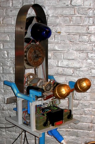
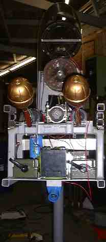
The central part of this computer controlled musical automaton, made and designed in the year 2000, is a robust free standing module containing all the control electronics, microprocessors, the power supply and three automated instruments: 2 shakers (maracas) and one large siren. The design of this module resembles an altar piece, maintaining strict symmetry. The central part is formed by the motorized and belt driven heavy duty siren. In top, a large voltmeter reflecting the electrical state of the instrument. Voltmeter and siren are covered with an arc made of stainless steel.On the backside of the voltmeter, a rotating blue flashing light is mounted. From the underside of the instrument we see a row of six XLR connectors. Here the wires feeding the <Springers> originate. These <Springers> are a computer controlled assembly of maximum six free standing percussive instruments using very large springs. All spring sound sources incorporated in the <Springer>-instruments are highly reverberating and can be placed, far away from the control unit, freely in a large space. In suitable spaces, the springs can be suspended, without using their tripods, as well. In all cases, the springs end on large resonators made from stainless steel and hardened brass, placed on the floor on special adjustable stands. The automate was designed to be pretty monumental since it had to fill the forum of the Technical University in Eindhoven, a space with a very high ceiling.
 The instrument
can be played by standard MIDI commands and a midi implementation table
is given further below on this web page.
The instrument
can be played by standard MIDI commands and a midi implementation table
is given further below on this web page.
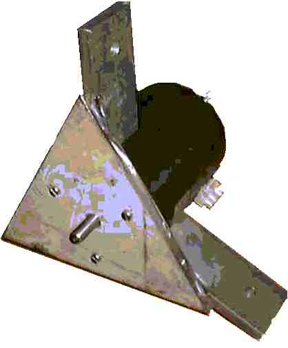
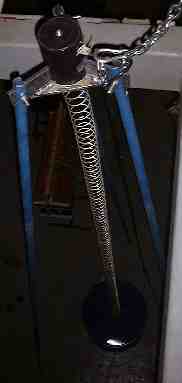
The picture to the right is a detail of the top part of the tetrahedral structures from where the springs are suspended. The large cylindrical object is the hefty solenoid activating the springs.
Six of these components form the top vertexes of six tetrahedral structures with legs ranging in lengths as shown and chosen from the table below:
| Leg length | h min. (at 60 degrees, tetrahedron) | spring length including eyelets. | Barrel resonator height | springrate |
| 6000 mm | 4896 mm | 4010 mm | 886 mm | 1.8 N/mm |
| 4920 mm | 4015 mm | 3434 mm | 580 mm | 1.8 N/mm |
| 4080 mm | 3329 mm | 3029 mm | 300 mm | 1.8 N/mm |
| 3360 mm | 2742 mm | 2522 mm | 220 mm | 1.8 N/mm |
| 2820mm | 2301 mm | 1750 mm | 500 mm | 1.8 N/mm |
| 2340mm | 1909mm | 1550 mm | 400 mm | 1.8 N/mm |
 The springs were
in the original version (year 2000) attached to large empty oil barrels
(200 liter, for the largest selection of leg lengths, for the smallest
selection, 100 liter) serving as amplifiers. For one of the springers
however, we constructed a resonator from an old circus bass drum, by providing
it with a single brass membrane to which the spring is attached. The resonance
of the latter construction was so much better that we replaced the oil
barrels for all the other springers with similar resonators using hardened
brass in 2008. Since we had no more metal bass drum bodies available,
we constructed the flanges from stainless steel. This greatly improved
the sonic result and it also made transportation of the entire instrument
a lot less voluminous and cumbersome. The legs for each one of the springer-modules
are made of 3/4" gas tubing, reinforced at the slotted ends. These
legs have steel feet such that they are stable even on very polished and
slippery floors. If placed in open air, on ground or grass vegetation,
the feet can be left out of the set up.
The springs were
in the original version (year 2000) attached to large empty oil barrels
(200 liter, for the largest selection of leg lengths, for the smallest
selection, 100 liter) serving as amplifiers. For one of the springers
however, we constructed a resonator from an old circus bass drum, by providing
it with a single brass membrane to which the spring is attached. The resonance
of the latter construction was so much better that we replaced the oil
barrels for all the other springers with similar resonators using hardened
brass in 2008. Since we had no more metal bass drum bodies available,
we constructed the flanges from stainless steel. This greatly improved
the sonic result and it also made transportation of the entire instrument
a lot less voluminous and cumbersome. The legs for each one of the springer-modules
are made of 3/4" gas tubing, reinforced at the slotted ends. These
legs have steel feet such that they are stable even on very polished and
slippery floors. If placed in open air, on ground or grass vegetation,
the feet can be left out of the set up.
The instruments were originally made and designed to be a part of the <Slag-Werk> project realized for 'Web Strikes Back' at the occasion of the Tromp biannual, October 2000 in Eindhoven, the Netherlands. In that project the installation was controlled by the internet: people could submit playing instructions to the automate from anywhere in the world. Audio feedback to the participants, using webcasting, was implemented as well.
The <Springers> use dedicated hardware, designed for musical automata such as player pianos, percussion instruments, organs and even bowed instruments. The first version of <Springers> used a laptop computer for controlling the different components of the instrument. In 2006 we revised the instrument such that it since than can take midi input directly. It has a couple of microcontrollers taking care of all electromechanical controls.
The hardware in the control module consists of a single board carrying the PIC microprocessor and a few more circuit boards for the different power supplies required.
The power Mosfets we used for controlling all solenoids are IRL640 , since these switch on TTL levels and are capable of dissipating 60 Watts. The current rating is 17 A and their Uds limit is 200 V. The rather high gate capacitance (850 pF) is not a real problem since switching speeds in this application are inherently pretty slow. For this reason we did not fit a resistor between gate and ground in the driver circuit. Note that when the power supply is switched on, all PIC outputs may go to a high state, thus sounding all springers at the same time. To avoid this, users should always first switch on the 5V power supply and only when the PIC controller has started up, switch on the high voltage power supply for the solenoids. Hence the dual switch in the power supply.
The power supply for this instrument is rated for 440 Watts. It consists of different sections:
- a.- high power section for the solenoids as well as the siren: 80 V / 335 W. This voltage can be read on the very large rather antique looking voltmeter mounted in top of the instrument.
- b.- logic power section: 5 V / 1 A, mounted on separate power supply board.
- c.- high power section for the rotating flashlight: 24 V / 100 VA. (SMPS)
Solenoids:
For the <Springers> we used solenoids made by August Laukhuff, Weikersheim, type number GL90A/15. Officially these are rated 24V at 1.41A. At these conditions, they deliver a power of 55N. Anchor displacement is 25mm and cannot be modified. We took the solenoids to the lab, and derived following table describing operational conditions relevant to our application:
| maximum duty cycle | 100% | 50% | 25% | 10% |
| Power (at 20 Celsius) | 34W | 76W | 135W | 300W |
| Voltage | 24V | 36V | 48V | 72V |
| Maximum ON-time | no limit | 360" | 36" | 3" |
The springers are connected
to the control module with long cables ending in female Neutrik or XLR
connectors. For the largest springers, mapped on notes 120, 121,122 and
123 we used XLR-LNE high voltage types wired as shown. At
the first revision of the instrument in 2006, we added outputs for two
more springer elements mapped on the notes 118 and 119, but since the
original type of connector XLR-LNE (produced by Cannon and Neutrik) is
no longer in production, we used for these outputs two normal female audio
type 3-pole XLR connectors. On these the solenoids are connected between
pins 2 and 3. Ground or pin 1 is connected to the chassis but not used
nor connected on the solenoid side. The female connectors are situated
on the underside of the control module. Activation repetition rate is
limited by the solenoids in combination with the spring-loads. Maximum
pulsing frequency is about 65 Hz. Of course fast repetition rates are
only possible when using small values for the velocity byte.
At
the first revision of the instrument in 2006, we added outputs for two
more springer elements mapped on the notes 118 and 119, but since the
original type of connector XLR-LNE (produced by Cannon and Neutrik) is
no longer in production, we used for these outputs two normal female audio
type 3-pole XLR connectors. On these the solenoids are connected between
pins 2 and 3. Ground or pin 1 is connected to the chassis but not used
nor connected on the solenoid side. The female connectors are situated
on the underside of the control module. Activation repetition rate is
limited by the solenoids in combination with the spring-loads. Maximum
pulsing frequency is about 65 Hz. Of course fast repetition rates are
only possible when using small values for the velocity byte.
The <Shakers> use bi-directional solenoids of the same type as we used in <Thunderwood> for the thundersheet as well as for the bamboo windchimes.
The siren is driven by one of the hardware PWM programmable pins on the microprocessor , and uses a strong DC motor. This motor drives the siren through belts. The motor belt wheel is 40mm, whereas the siren wheel measures 140mm. For safety reasons we limit the speed of the motor by using 70V dc as maximum voltage. The motor when driven with 210V dc rotates at 7000 rpm. Not only would the siren turn dangerously fast, but also -since sirens have sound pressure output proportional to pitch- it would become largely over 120dB in loudness at an earpiercing pitch...
For the rotating flashlight, requiring 24V at 3A for full speed operation, we used the second PWM programmable PIC controller pin in a very similar way. To power this part of the engine, we used a standard switched mode power supply made by Sunpower and rated for 24V at 3.5A.
The wiring to and from the PIC controller board looks like:
 Music:
Midi mapping:
- Largest springer: note 36 [in version1: 120]
- Second largest springer: note 37 [was 121]
- Third largest springer: note 38 [was 122]
- Smallest springer: note 39 [was 123]
- Extra suspended springer 1: Note 40 [was: 118]
- Extra suspended springer 2: Note 41 [was: 119]
- Shaker 1 : notes 72-73 [was:124-125] (alternating)
- Shaker 2: notes 79-80 [was:126-127] (alternating)
- Siren: note 24 [was 1], velo: 0-127. Pitch bend implemented (unipolar).
- Rotating flashlight: controller 70, value 0-127 [was note 2, velo 0-127]
- For those who rather want to see this on a musical staff:
- The mapping we used for version 1 still works, such that previously composed pieces using <Springers> will still work without changes. However, new pieces should only use the new mapping.
- Pitch bend with 14 bit resolution is implemented for the siren. The implementation is unipolar 0 to 16383. With the pitch bend MSB set at 127, the siren will sound its middle pitch. Note that it is required to give a note-on command for note 24, prior to sending a pitch bend command.
- Midi channel: 7 (offset 0)
Program change: 0, 122-127 select different velocity lookup tables. The velocity scaling lookup tables can be programmed using sysex commands. 0 is the original, non-reprogrammable mapping. It is recommended to allways use 122, which contains an optimised mapping.
Wave samples (click to play or download):
Concerts where <Springers> could be heard:
- Tuesday 17th of October 2000: Logos Tetrahedron: Try out concert
- Tuesday 24th to Sunday 29th of October 2000, Eindhoven, TU: <Web Strikes Back Project>
- Thursday august 2nd 2001, Ghent: Logos Tetrahedron
- Sunday September 9th 2001, Sint Truiden, Flam Ijzergieterij (10u00-18u00)
- M&M concerts in 2001 and 2002.
- Thursday November 28th 2002, M&M in Enschede.
- M&M concert on December 19th 2002, Ghent, Logos tetrahedron.
- M&M concert on January 15th 2003, Ghent, Logos Tetrahedron
- M&M concerts (monthly) from January 2004 on.
- M&M concert 14.09.2006: presentation of the renewed version of <Springers>
- Sunday November 5th, Koeln, Alte Feuerwache: 50 years computer music festival
- M&M concert 20.02.2007: Early Springs.
- M&M concert 18.10.2007: Sensations: Hybrid Sensing Study #1.
- M&M concert 16.09.2008: Sensing concert
- M&M concert 17.02.2009: Mini's concert
- M&M concert 18.06.2014: Dances concert
- all robot orchestra concerts in the Logos Tetrahedron since.
- SMAK, Ghent exhibition, september 2021
- nearly all Robotorchestra concerts in 2022 and 2023
- August 2023: <Springers> has an important part in 'Twin Towers' by Godfried-Willem Raes
- september 2023: <Springers> joins the party in Berlin for the opera production Zeroth Law with Gamut Inc. (Deutsche Oper Berlin)
Mechanics:
The sketch shows the way the shaker solenoids are connected to the shakers. Underneeth is the axis of rotation (8 mm). Ca. 30 mm above this point another pivoting point forms the actioning point . The last pivoting point is drilled laterally through the anchor of the solenoid. The picture shows the final realization.
Construction collaborators:
- Filip Switters
- Kristof Lauwers
- Moniek Darge
- Kurd Vandevelde
- Johannes Taelman (PIC firmware 2006)
Dimensions:
- Control module:
- height: 1650 mm
- depth & width: 450 mm
- circular base: 500 mm diameter
- weight: ca. 65 kg
- Power consumption: 440 Watts / 230 V AC
- data input: MIDI in
- data outputs: 5 x MIDI THRU
- Springers (4 to 6 modules):
- width: 1600 mm to 6200 mm
- height: 5000 mm (cf.. Table)
- depth: 1600 mm to 6200 mm
- weight: 60 kg to 100 kg each
Insurance value: 11.750 Euro.
Note for organizers: these instruments are very high and cannot be taken into parts. Make sure the space you provide allows for the height of this instrument. Also access routes to the space have to be carefully checked beforehand. <Springers> are collapsible and can easily be positioned and repositioned. This project is suitable for open air performances, since we can put small umbrellas over the top ends of the tetrahedrons. However, this project cannot be battery operated, so mains voltage is required. For transportation, a truck capable of taking a load of 6m20 in length, is required. Springers can also be set up as an audio art installation, with radar based audience interaction. If required we can consider modifying the space requirements, heigthwize.. If the springers can be suspended from a strong enough ceiling, we can also suspend the springer modules thus reducing transportation requirements to a normal small truck without elevator.
The <Springers> automaton can be heard on the Logos Public Domain CD <Automaton> (LPD007). as well as on LPD CD <Robodies> (LPD014)
| Back to Web Strikes Back | Back to logos' main index page | To homepage Godfried-Willem Raes |
Maintenance and repair logbook:
- 01-09.2000: First version of <Springers>, made for the Tromp competition in Eindhoven, Netherlands. Springers can be controlled through the internet directly and set up as an audio installation. It requires its own laptop computer with a parallel printer port. (LPT1).
- 28-08.2006: Start revision of <Springers> for direct midi operation. We can use a single PIC controller. File describing the original version moved to archive.
- 29.08.2006: New controller boards soldered. We use a PIC 18F2525. Two extra springer outputs will be added. Original circuitry removed.
- 30.08.2006: We keep the original 5V power supply. This board also has a symmetric +/- 15 V power supply which in this version is not used. New carrying board constructed for the microprocessor board. Extra holes drilled to accommodate the two normal female 3-pole XLR connectors.
- 31.08.2006: Flashlight power supply changed: now a Sunpower SMPS 24 V/3.5 A. Logos display added in front (works on 5 V DC).. Extra transformer (12 V/100 VA) added in series with the existing one, to raise the voltage for the solenoids to 76V. Blue LED spotlight underneath added. This lite is always on as soon as the high voltage is switched on. Voltmeter repaired. It also serves as a discharge resistor for the high voltage power supply. (RC time = 1'). GMT coding updated.
- 01.09.2006: PIC's programmed with Johannes Taelman. Springers works again and from now on it is a midi robot.
- 02.09.2006: test session under GMT.
- 15.09.2006: A fifth springer mechanism welded in stainless steel. Also the spring will be stainless steel as well, the size smaller than the smallest of the already existing 4 springers. Height about 3m50.
- 16.09.2006: Springer 5 to be suspended. The resonator is a stainless steel bowl..
- 17.09.2006: Finishing work on stainless steel bowl-resonators. For suspension, chains are to be used.
- 09.10.2006: PIC revision to allow for sysex velocity scaling lookups. Pitch bend now requires a note on command. It uses the full 14 bit bend range in unipolar mode, thus pitch bend 0 means siren at standstill and pitch bend at maximum value will be highest pitch. Setting pitch bend to msb = 64 will thus produce the midrange pitch. To switch the siren off, a note off command must be send.
- 21.10.1006: New chains constructed and assembled for the suspension of the springers.
- 23.10.2006: Design for a separate PIC control board such that we can use the springers alone in an installation project abroad without having the ship the entire and heavy module.
- 04.12.2006: Price calculation for transport to New York.
- 16.02.2007: Fifth springer mounted in tetrahedron. This one uses a stainless steel spring.
- 10.06.2008: Design for new brass resonators for all springers.
- 31.08.2008: Stainless steel hoops ordered from Demar Lux. GMT testcode upgraded.
- 13.09.2008: Start construction of the new resonators, using brass membranes mounted on stainless steel hoops.
- 14.09.2008: First prototype for the new series of resonators finished. Membrane sounding free diameter 520mm. Brass type MS58 (engraving quality brass), thickness 0.8mm. The long nuts welded on the underside of the flanges are M12 threaded, for mounting of the legs.
- 15.09.2008: Start works on the second new resonator, same diameter as the first one, but here we will use thinner brass for the membrane (same type as used on the bass-drum body). Stainless steel (thickness 0.5mm) could also be considered here. For the TIG welding of the long M12 nuts on the rims, we used the trick with the red copper bolt inserted in the nut for cooling, thus preserving the integrity of the thread.
- 16.09.2008: Evaluation of the two new resonators made sofar: the resonator using hardened MS58 sounds by far better than the one using 0.5mm brass. This despite the much lower resonant frequency of the latter one. Tension on the brass membrane may be too low, or the spring should be suspended from a higher point.
- 2016: Due to a complete cut of our subsidy, we cannot further develop this robotic project. Corruption reigns in the advisory boards...
- 01.09.2021: Springers set up in the SMAK museum. Mains voltage there was found to be as low as 216 V, thus the springers couldn't be sounded at the same sound level they normally sound at Logos.
- 03.07.2023: Checked and found out to be o.k.
- 22.08.2023: Replacing the XLR-LNE sockets with regular XLR a pole
chassis parts. We have only three in stock though... so finalisation
may be on hold for a while. Here is a picture of the obsolete connectors:
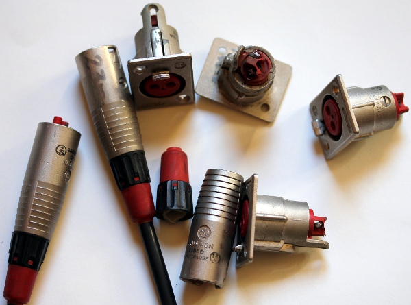
- 23.08.2023: All sockets on the main module replaced with regular 3-pole XLR types. The solenoids are to be connected to pins 2 and 3. Pin 1 is unconnected on the chassis but can be used as a ground. Although we recommend the use of 1.5mm2 section wire, in an emergency it also should be possible to use regular microphone leads. Start preparing cables for the Berlin production.
Last update:23-08-23