|
|
|
<Qt>
dr.Godfried-Willem
RAES
Ghislain
& Dierik POTVLIEGHE
Johannes
TAELMAN
Kristof
LAUWERS
2005 -
2008
onderzoeksprojekt
rond de ontwikkeling van nieuwe expressiemiddelen van de School of
Arts, Hogeschool Gent
|
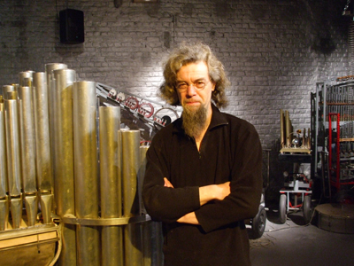
Quartertone organ module: <Qt>
The research and development of this instrument building project is an intensive
collaboration in the realms of artistic research under the auspices of the University
College Ghent (Hogent), department of music and the Logos Foundation. On the
practical level, this organ is the result of an intensive collaborative effort
by Ghislain Potvlieghe (specialist in historic organ building) and dr.Godfried-Willem
Raes. The development of the PIC firmware in assembly language used to control
this robotic organ is in the hands of Johannes Taelman. Research into practical
and historical repertoire for such a novel quartertone instrument, was done
by Sebastian Bradt (Hogeschool Gent). The driver software developped within
the GMT language was written by Kristof Lauwers (Logos Foundation).
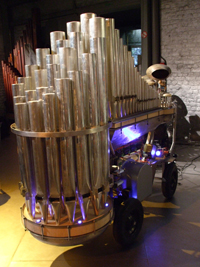
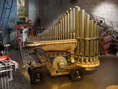
The main purpose was to build a wide ambitus organ register tuned in equal
temperament quarter tones. The instrument should be capable of automatic playing,
controlled by computer software, as well as through a set of two conventional
keyboards. The whole instrument had to be easily transportable, dictating the
use of brass and or pure tin/antimony pipework instead of the traditional lead/tin
alloy. The range covers 6 full octaves (from midi note 36 to 108) . Wind pressure
modulation can be used to expressive purposes. Tremulant effects as well as
accented notes are a possibility. Subtle and individual touch velocity control
is implemented.
The pipes are constructed after the following early prototype, made of brass
and sounding midi note 77:
For the actual realisation, we decided to make use of an alloy composed of
95% tin and 5% antimony, leading to mechanically quite strong and leadfree pipework
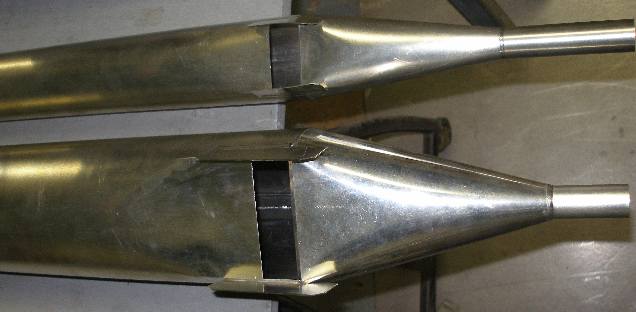
that also will hold tuning very well. Experiments relative to the mechanical
strength of Sn-Pb soldered brass pipes have shown that these are pretty sensitive
to breaking under shock conditions. The heterogenity of the materials being
at the origin of this weakness. The picture below shows the labium and pipefeet
for the prototype pipes sounding notes 36 and 48.
Qt is internally controlled by thirteen PIC processors. Twelve processors (PIC
18F4620-I/P) are used to control each set of 72 solenoids used to operate the
valves in the windchest, whereas the thirteenth PIC (18F2525-I/SP) steers the
compressor motor functions and the windpressure modulation. For the latter two
precize stepper motors are used to drive valves inside the conducts leading
to the upper and the lower windchest. We opted for the MicroChip PIC18F4620
because of its 64kByte flash program memory (good for 32768 single word instructions)
, 3986 bytes static RAM, 1024 bytes Eeprom and last but not least, its 36 available
I/O pins. With these specs it became possible to use a single chip to control
14 notes, since each note requires 2 I/O pins. The PIC 18F2525 follows the same
architecture but has only 25 I/O pins and 48kByte flash program memory. Enough
in any case for the requirements of motor control and feedback in this design.
The upperplate of the windchests under which the solenoid valves are mounted,
is made from very thick african obeche (or wawa) wood. This wood is very good
for wood cutting and carving, an essential feature since we had to bring the
wood to an exact and airtight matching with the curved metal work, using chivels.
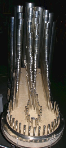
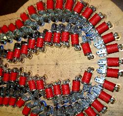
The arrangement of the lowest octave of the pipes on the lower windchest is
as follows: The
pipes 47 and 47.5 are in the very front of the instrument. The arrangement for
the high windchest is:
The
pipes 47 and 47.5 are in the very front of the instrument. The arrangement for
the high windchest is:  The notes are numbered in fractional midi, note number 60 corresponding to middle
C on the piano keyboard.
The notes are numbered in fractional midi, note number 60 corresponding to middle
C on the piano keyboard.
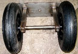
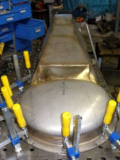
The entire Qt module is mounted on 4 large wheels and thus is, although pretty
heavy (ca.220kg) , also very transportable. All metal work for the two windchests
and the entire chassis was realized using the TIG welding process (manual) on
AISI 304L stainless steel.
- Design, research & construction: Dr.Godfried-Willem Raes
- Pipe work: Ghislain Potvlieghe
- Tuning and intonation: Dierik Potvlieghe
- PIC microcoding: Johannes Taelman
- Software integration in composition software: Kristof Lauwers
- Collaborators: Sebastian Bradt, Kris De Baerdemacker, Hans Roels, Moniek
Darge, Xavier Verhelst.
Technical specifications:
sizes: length: 2000mm, width: 700mm, height: 1760mm.
power: 230V - 950Watt (peak)
weight: 226kg
Control: midi protocol, using 2 channels. Note ON/OFF with velocity implemented.
Volume controller (7) used for wind pressure. Controllers nr. 1 and 2 for wind
valve control and tremulant effects. Other controllers may be added later. Direct
control via UDP/IP network is under development.
Wiring overview:
Electronic circuitry:
For <Qt> either the use of pallet valves or conical valves in the windchest
were first under investigation. We were after a maximum touch sensitivity for
this organ, such as to make it sound like an ancient mechanical organ positive,
where the player can in fact control a little bit the onset of the pipe sounds
by modification of the speed wherewith the keys are depressed. Conical valves,
in combination with softshift solenoids do indeed work extremely well to this
end. (cfr..the use of a single conical valve in our automated
saxophone). However, each valve has to be made on the lathe and the cones
have to match perfectly well with the conical holes in the windchest upper plate
itself. Not an easy matter, particularly since wood was proven to be unsuitable.
A massive upperplate from metal was investigated but rejected due to the extraordinary
weight it would add to an instrument that was meant to be transportable. Synthetic
materials such as glassfiber reinforced epoxy were tried, but are not commercially
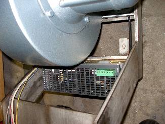
available in the sizes we needed. Thus we decided to go back to our well known
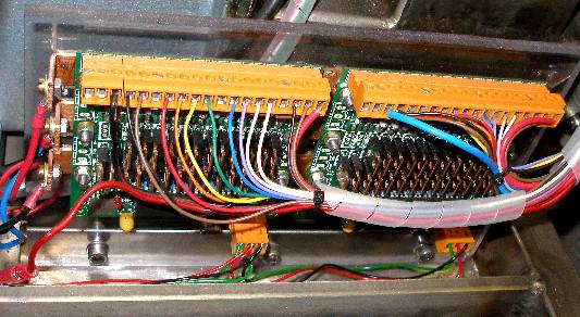
pallet valves. They can be seen on the picture showing the internal view of
the upper windchest (notes 48-108). To get a better sensitivity to velocity, we modified the spring tension. Normally
a spring is used to keep the valves just closed at rest. So the force is just
a bit larger than the downwards force excerted by the weigth of the valves,
since they are mounted upside down. By increasing this force above this minimum
required for keeping them closed at rest, the valves gain a more gradual opening
traject, at the detriment however of some response speed. The circuit we developed
for achieving a bit of velocity sensitivity from these solenoid operated valves
looks like this:
To get a better sensitivity to velocity, we modified the spring tension. Normally
a spring is used to keep the valves just closed at rest. So the force is just
a bit larger than the downwards force excerted by the weigth of the valves,
since they are mounted upside down. By increasing this force above this minimum
required for keeping them closed at rest, the valves gain a more gradual opening
traject, at the detriment however of some response speed. The circuit we developed
for achieving a bit of velocity sensitivity from these solenoid operated valves
looks like this:
This circuit is a further development of the circuits we used in the design
of our <player pianos> and <Harma>.
The PNP transistor we used in these earlier designs is here replaced with a
p-channel mosfet (BS250 or similar type). The gate goes directly to ground and
the zenerdiode, essential in the bipolar design, could be left out. In this
new design the negative pulse driver mosfet has to be a logic level type, identical
to the hold-driver mosfet. Note that, due to the gate capacitance of the negative
pulse mosfet (ca. 1.5nF), there is a inherent timeconstant in the order of 7
microseconds. Since the PIC's minimum pulse duration is 19.2 microseconds, this
does not lead to a performance penalty. A single PIC controller (Microchip PIC
18F4620 - I/P) can steer 14 notes. For the low windchest we thus use two boards,
leaving four outputs unused for notes (they can be used for light effects).
For the high windchest, ten boards in total. The prototype PC board looks like:
 It was developed
in Eagle software for PCB design and produced from the datafiles at Eurocircuits
in Hungary. (Plot & Go). The first batch had a wiring bug, repaired in our
second (gold layered) production batch.
It was developed
in Eagle software for PCB design and produced from the datafiles at Eurocircuits
in Hungary. (Plot & Go). The first batch had a wiring bug, repaired in our
second (gold layered) production batch.
The midi input board is designed after the following schematics:
Here we have merely the compulsary optocoupler input with reverse polarity
protection diode. The selection of resistors around the optocoupler is quite
critical if you want to achieve optimum speed and no data loss even with midi
back-to-back data streams. In the practical realisation we substituted the 6N138
type originally specified, by a 6N137, leading to a fivefold improvement in
speed. Next the inverted output signal, on TTL levels, is fed to 10 inverter
buffers which will drive the many note valve steering boards:
To allow users easy star-like connections to many more robots and automats,
we provided this circuit also with no less then 5 real midi-thru drivers and
corresponding 5pole din connectors:
Still on the very same PC board, we found place for a PIC microcontroller to
be used for the control of the motor functions, lights, tremulant and other
optional effects:
The board offers buffering for the midi signals to be fed into the very many
pulse/hold driver boards as well as a single PIC controller (PIC18F2525-I/SP)
, in charge of wind control for the radial compressor. Extra bit outputs are
provided for the expression control: two stepping motor driven tremulants etc.
Two pins are configured as inputs and used to read the output of the MLX90316
Hall Effect based rotary position sensor IC's. These are mounted on the axis
of the wind valves.
At last, almost as a reminder, however an essential one, DC voltage buffering
and decoupling with ample 100nF caps has been foreseen in the design:

The actual external wiring for this PC board looks like:

The specifications of the pallet solenoids used in the windchest are: 12/14
V dc, 75 Ohm resistance, 190 mA current. The Laukhuff order numbers are given
in the list of materials at the end of this
document. Cost: 3800 Euro. The original springs in the valves (0.4 x 3.4 x 26)
were replaced by custom made stronger types by us (0.5 x 4.5 x 25) , this to
allow for note aftertouch control.
The windvalves in the lower and upper windchest can be used both as windpressure
expression controls and as tremulants. These valves are controlled by stepping
motors and controllers wired after this schematic:
If we take the static windpressure in the windchest as 150 mm H2O
(15 mB, 1.5 kPa or 1500 N/m2), then the worst case static force on the windvalves
(100 mmx150 mm = 1.5 dm2 in surface) is 22.5 Newton. This force however only
applies if the other side of the valve is fully opened.. Such circumstances
could only exist under full cluster conditions, where the wind pressure will
collapse anyway. Under normal conditions, the pressure difference between both
sides of the valves will be limited to ca. 5%. In addition to this consideration
it must be noted that in our design, very much on purpose, the valves do leak.
Otherwize, they would fully interrupt the tones produced rather than cause a
smoorth amplitude (and a bit of frequency-) modulation. So the stepper motor
we selected should under all normal circumstances be powerfull enough to rotate
this valve. The manufacturer gives following force curves for the given (Sanyo)
controller and stepping motor combination:

Since the current through the motor winding will fall back to 50% of the normal
current within 200 ms after the last pulse on cw or cww is received by the controller,
the slowest possible tremulant frequency will be ca. 0.06 Hz. The pulsing frequency
would than be 6 Hz. This is also the slowest possible fluent speed of any valve
movements. The pulse timing requirements and constraints are summarized in the
graph below:
The specifications for the motor and compressor are:
- Nominal pressure: 120 mmH20 (12 mBar) - 8 m3/min
- Year of construction: april 2006 - nr. 29790
- Motor data: 0.45 HP, 230/400 V - 1.5/0.9 A , 2800 rpm @ 50Hz
- Cost: 1850 Euro
Note that the operational pressure is higher. Qt was intonated and tuned on
a pressure of 140 mmH20 (14 mBar).
MIDI-Implementation table for <Qt>
| Midi command |
status byte |
byte1 |
byte 2 |
remarks |
| Note Off |
128 + 5 |
note (36-108) |
0 |
release not implemented |
| |
128 + 6 |
note(36-107) |
0 |
release not implemented |
| Note On |
144 + 5 |
note (36-108) |
velocity |
velo=0 = note off |
| |
144 + 5 |
note (36-107) |
velocity |
velo=0 = note off |
| Key pressure |
160 + 5 |
note (36-108) |
note pressure |
only if ctrl.69 is ON |
| |
160 + 6 |
note (36-107) |
note pressure |
only if ctrl 69 is ON |
| Program Change |
192 + 5 |
velo lookup selection
122 = default
120-127: tables
|
- |
look ups are sysex programmable |
| |
192 + 6 |
velo lookup selection, as above |
- |
look ups are sysex programmable |
| Controller |
176 + 5 or + 6 |
1 |
low windvalve position |
0= closed, 127 = opened |
| |
176 + 5 or + 6 |
2 |
high windvalve position |
0 = closed, 127 = opened |
| |
176 + 5 or + 6 |
7 |
wind pressure motor |
normal value = 102 |
| |
176 + 5 or + 6 |
8 |
light strenght |
blue LED spotlites |
| |
176 + 5 or + 6 |
11 |
low tremulant speed |
normal value = 96 |
| |
176 + 5 or + 6 |
12 |
high tremulant speed |
normal value = 96 |
| |
176 + 5 or + 6 |
66 |
0 or not 0 |
wind motor on off switch |
| |
176 + 5 or + 6 |
67 |
0 or not 0 |
low valve motor power off |
| |
176 + 5 or + 6 |
68 |
0 or not 0 |
high valve motor power off |
| |
176 + 5 or + 6 |
69 |
0 or not 0 |
enable/ disable poly aftertouch |
| |
176 +5 or + 6 |
70 |
0 or not 0 |
enable/disable hold (stacc. mode) |
| |
176 + 5 or + 6 |
123 |
0 |
all notes off |
| Channel aftertouch |
208 + 5 |
low windvalve position |
- |
same as ctrl 1 |
| |
208 + 6 |
high windvalve position |
- |
same as ctrl 2 |
| Lights: |
144 + 5 |
35 |
0 or not 0 |
lights lower windchest K-side |
| |
144 + 6 |
35 |
0 or not 0 |
lights lower windchest Q-side |
| |
144 + 5 |
110 |
0 or not 0 |
light tail upper windchest |
| |
144 + 5 |
111 |
0 or not 0 |
light Kside upper windchest |
| |
144 + 6 |
111 |
0 or nor 0 |
light Q side upper windchest |
| |
144 + 5 or +6 |
120 |
0 or not 0 |
light BIM box 5V supply |
| SysEx |
|
|
|
to be documented later |
| |
|
|
|
used to program different velo scalings |

Music composed for <Qt>:
- Godfried-Willem Raes "Qt-Split", for Picradar interfaces and two
nude performers
- Thomas Smetryns "Und der Dichter spricht, spricht der Dichter"
- Yvan Vander Sanden
- Frank Nuyts: "Two Quartertone pieces don't make a half one"
- Godfried-Willem Raes "Gestro Qt"
- Godfried-Willem Raes "Qua Qt", quadrada study #12 for Qt.
- Wouter Simoens "Kompositie voor een kwarttonen orgel"
- Sebastian Bradt "Taxidermie", for Qt
- Barbara Buchowiec "Mars of the liliqts" for Qt and viola
- Godfried-Willem Raes "Wouwel"
for Qt.
 Recording
- Godfried-Willem Raes "Qtree" for Qt
- Godfried-Willem Raes "Akafest" for Qt
- Karel Miry "De Vlaamse Leeuw" (quartertone version) Recording
- Hans Roels
- Kristof Lauwers
- Kris De Baerdemacker "voor qt en orgel"
- Judy Dunaway "Duo for Qt and balloon"
- Pieter Corten
- Jelle Proost
- Gamut Inc. 'Zeroth Law'
- Benjamien Lycke "Bagatelle pour Qt" (2010)Recording
Nederlands:
Kwarttoons orgel : <Qt>
Qt is de roepnaam van een postdoktoraal experimenteel artistiek onderzoeksprojekt,
officieel gestart op 1 oktober 2005, onder de auspicien van Hogeschool Gent
in samenwerking met Stichting Logos. De wetenschappelijke ondersteuning en praktische
leiding was in handen van dr.Godfried-Willlem Raes, docent kompositie, akoestiek,
klankonderzoek en onderzoeksmetodiek aan het departement muziek en drama. Dit
geautomatiseerd orgel kwam praktisch tot stand als een samenwerkingsprojekt
van Ghislain Potvlieghe (specialist historische orgelbouw), Dierik Potvlieghe
(orgelbouwer), Johannes Taelman (ontwikkeling en research inzake mikrokontrollers
voor de besturing), Sebastian Bradt (onderzoek naar aktueel en historisch repertoire
op het gebied van de kwarttoonsmuziek en komponist van nieuwe muziek voor deze
automaat), Kristof Lauwers (ontwikkeling aansturingssoftware ten behoeve van
komponisten) en dr.Godfried-Willem Raes.
Het opzet bestond erin een zuiver getemperd kwarttoonsinstrument te bouwen
met een grote tessituur: minstens 6 oktaven (midi 36 - 108). Verder
gaat het in dit ontwerp om een zuiver akoestisch instrument, met pijpen dus.
De luchtdruk is ten dienste van de expressieve mogelijkheden op dynamisch vlak
goed en snel moduleerbaar, terwijl ook aksenten en tremulant mogelijk zijn.
De tremulant werd in twee onafhankelijke systemen uitgevoerd, waardoor de bas
een andere tremulant frekwentie kan krijgen als de diskant. De akoestisch opgebrachte
geluidsdruk diende bij dit ontwerp voldoende groot te zijn om in een orkestrale
onversterkte bezetting probleemloos te kunnen worden ingezet. Bovendien diende
de stemming zo vast te zijn, dat regelmatig bijstemmen van het instrument niet
nodig zou zijn. Daarom gingen we bij het ontwerp uit van aan de bovenkant dichtgesoldeerde
pijpen. Transportbestendigheid en verplaatsbaarheid waren een belangrijke eis.
Deze eis sluit bij voorbaat het gebruik van klassieke legeringen voor orgelpijpen
(60% tin, 40% lood in het beste geval) uit. Deze zakken immers bij blootstelling
aan trillingen, onvermijdelijk bij verplaatsingen, door onder de druk van hun
eigen gewicht. Ook louter ekologische (en sedert kort ook Europees wettelijke)
overwegingen pleiten trouwens tegen het gebruik van lood. Proeven werden gedaan
met messing enerzijds en legeringen bestaande uit 95% tin en 5% antimoon anderzijds.
De met Sn-Pb gesoldeerde messingpijpen bleken erg gevoelig aan breuk op de soldeernaden.
(cfr. <Puff>). Hardsolderen of brazeren ware ook
mogelijk, maar technisch erg lastig uitvoerbaar gezien de vereiste precizie.
Lassen van messing, de meest superieure techniek, bleek -althans voor ons- zo
goed als ondoenbaar omwille van de onstabiliteit van de legering (het zink oxydeert
namelijk). Uiteindelijk opteerden we dan maar voor de volledig loodvrije pijpen
uit tin en antimoon, een legering waarmee ook traditionele orgelbouwers goed
overweg kunnen. Omwille van de gewenste hardheid, opteerden we in ultimo nog
voor de toevoeging van 1% koper in de legering: 95% tin, 4% antimoon, 1% koper
werd het dus uiteindelijk.
Omwille van de gewenste mobiliteit van het instrument, werd het integraal op
goed stuurbare grote wielen met massief rubberen banden gemonteerd en werden
de afmetingen toch zo kompakt mogelijk gehouden. Deze voorwaarde dikteerde welhaast
automatisch het gebruik van gedekte pijpen evenals een betrekkelijk hoge winddruk
(100 tot 150 mm waterkolom, of 10 tot 15 mBar).
Het chassis en alle metalen delen voor de beide windladen en de kondukten werd
uitgevoerd in minstens 3 mm dik roestvast staal AISI304L en AISI316 onder gebruikmaking
van het volledig manuele TIG lasproces. Als toevoegmateriaal bij het lassen
werd uitsluitend AISI316 gebruikt. Het snijwerk werd uitgevoerd met een hoogfrekwent
plasma brander. Voor de afwerking werd volstaan met een grove borsteling met
een inox komstaalborstel. Aan de binnenzijde werden alle lasnaden, omwille van
het beperken van ongewenste turbulenties in de windstroom, zorgvuldig gladgeslepen.
Gezien deze opties in materiaalkeuze, moet het instrument kwa duurzaamheid zeker
aan alle stelbare eisen kunnen voldoen.
De volledige MIDI-implementatie, ten behoeve van eenvoudige gebruikers, publiceerden
we aan het eind van de engelse tekst hierboven. Deze implementatie maakt ook
een manuele bespeling via twee elektronische midi-keyboards eenvoudig mogelijk.
Voor het speelkomfort is het wel aangewezen keyboards te gebruiken met een tessituur
van zes oktaven en met individuele touch sensitivity. De beide keyboards worden
via een midi-merger rechtstreeks op <Qt> aangesloten. Een rechtstreekse
netwerkbesturing onder gebruikmaking van UDP/IP is eveneens voorzien. Dit is
vele malen superieur aan Midi, maar in gebruik alleen weggelegd voor technologisch
onderlegde komponisten en musici. Voor wie met hetzij PD hetzij GMT overweg
kan, is dit het aanbevolen besturingssysteem.
Gedetailleerde berekeningen van de mensuren en dimensionering voor
de bouw van het Qt register:
Eerste proef, berekening op grond van proefpijp uit messingbuis. Mensurering
rekening houdend met handelsdiameters en korresponderende materiaaldiktes van
bestaande messing buis.
 link to look up table - naar overzichttabel
Tweede proef, berekening op grond van proefpijpen gesoldeerd uit een
legering 95% tin en 5% antimoon. De breedte van het labium werd hier bepaald
op grond van 1/4 van de omtrek van de cilindrische pijpen.
link to look up table - naar overzichttabel
Derde proef, berekening op grond van 5 proefpijpen
(36,48,60,72,84) gesoldeerd uit een legering 95% tin en 5% antimoon. Winddruk
85mm H20. De breedte van het labium werd hier bepaald op grond van 1/4 van de
omtrek van de cilindrische pijpen. Alle pijpen krijgen hier een individueel
verschillende mensuur.
link to look up table - naar overzichttabel
Berekend door dr.Godfried-Willem Raes op 13.03.2006 naar prototypes gebouwd
begin maart 2006. Het volledige register werd in elkaar gezet en gesoldeerd
door Ghislain Potvlieghe in diens atelier. De eerste verzameling pijpen (120)
was klaar op 22 mei 2006. Het kompleterende oktaaf 96-108 op 29.06.2006. De
stemming en intonering vonden plaats in verschillende werkfazen na de montage
van de pijpen op de afgewerkte windladen. (Oktober 2006- Maart 2007) De gebouwde
pijpen werden, na het stemmen (met dichtsolderen aan de bovenzijde) en intoneren
opnieuw exakt opgemeten en vergeleken met de berekeningen.
link
naar definitieve en samenvattende tabel van de mensurering voor Qt.
Bouw- en research dagboek:
- 15.08.2004: eerste tekeningen en berekeningen, uitgaande van het pijpwerk
van <Puff>
- 01.10.2004: Sebastian Bradt in dienst bij het departement muziek en drama
(Hogent) voor onderzoek rond mikrotonaliteit.
- 08.10.2004: bespreking konstruktie pijpwerk met Ghislain Potvlieghe
- 09.10.2004: eerste proefpijp (midi 60) gebouwd door Ghislain. Berekeningsprogramma
geschreven voor de mensurering van de Qt pijpen.
- 20.03.2005: Bespreking van de mogelijkheid de ontwikkeling van Qt als onderzoeksprojekt
voor te stellen, met Jan Rispens.
- 20.08.2005: Eerste ondertekening onderzoeksprojekt kontrakt tussen Hogent
en Logos.
- 01.09.2005: Werk- en overlegvergadering met Ghislain Potvlieghe. Inventarisatie
materialen.
- 03.10.2005: Eerste berekeningen windlade. Officiele start onderzoeksprojekt
Hogeschool Gent. Het projekt loopt over twee jaar en behelst een halftijdse
opdracht voor dr.Godfried-Willem Raes. (@70% weddeschaal..., ondanks kwalifikatie)
- 04.10.2005: Volgens de eerste berekeningen lijkt een gesplitste windlade
de beste oplossing.
- 05.10.2005: Plaatsing in een dubbele rij, eerder dan in rijen van 3 of 4
pijpen is voor de klankprojektie beter dan plaatsing in 3 of 4 rijen. De dubbele
rij organisatie kompromiteert evenwel sterk de transporteerbaarheid.
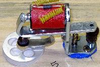
- 06.10.2005: Eerste tests voor de konstruktie van de elektromagnetische ventielen.
- 07.10.2005: Maximale repetitie-snelheid met een tegendruk van 12 mBar is
ca. 16Hz voor ventielen met een klepzitting van 23 mm en afdichting met kalfsleer
of het sintetisch equivalent, kalopel. Een Flatterzunge effekt is dus wel
haalbaar behalve wellicht op de grootste pijpen, waarvoor immers 35 mm grote
polsters moeten gebruikt worden.
 Dit type is afgebeeld op de foto.
- 11.10.2005: Konstruktie van een konisch testventiel voor evaluatie. Kegelventielen
laten principieel een soepele graduele drukregeling toe, maar reageren door
hun grotere massa alvast heel wat trager. Hun toepassing dikteert de toepassing
van tubular solenoids, zoals reeds eerder toegepast bij de bouw van onze player
piano's.
- 14.10.2005: Ontwikkeling software voor berekening van de dynamiek van de
pijpen in funktie van mensuur en winddruk. (PBCC compiler)
- 27.10.2005: research naar vermijding glitches in real time applicaties onder
Windows.
- 28.10.2005: bestudering mogelijkheid tot integratie van Qt in de orkestratie
van Workers Union van Louis Andriessen, een orkestratie uitgevoerd door Sebastian
Bradt.
- 01.11- 21.11.2005: Vedere proeven met kegelventielen en analoge besturing
daarvan. De eigenmassa van de kegels beperkt in hoge mate de repetitiesnelheid
en ook de responstijd van de ventielen. Proefkonstruktie gemaakt met uitgeholde
kegels, ter beperking van de eigenmassa. Dit is echter extreem arbeidsintensief.
Kegels blijken ook erg gevoelig aan vastklemmen, wat een erg hoge precisie
in het hoon- en polierwerk veronderstelt. De kegelventiel technologie blijkt
eerder geschikt voor automatische monofone blaasinstrumenten. De enorme kosten
wegen bij toepassing in orgels niet op tegen de voordelen.
- 25.11.2005: Labo tests met mini ventola blazers (5-7.5mBar) en Siemens M410
programmeerbare motor controllers voor fleksibele regelingen van de winddruk.
Een snelle regeling wordt beperkt door de inertie van de kompressorschoepen.
Hierdoor wordt de motor generatorisch in de afremfaze. Ook met DC injektie
in de wikkelingen blijft de regeling stug.
- 01.12.2005: proefopstelling voorbereiding met het reeds bestaande chassis
van <Harma>.
- 02.12.2005: programmering PIC's voor de pp boards zoals gebruikt voor de
player piano en voor <Harma>. PIC's 2- 8 zijn voor de aanslaggevoelige
ventielsturingen bedacht, terwijl PIC voor de sturing van de motor controller
moet instaan.
- 03.12.2005: experimentele opstelling met mini ventola blazer van Laukhuff
op een frekwentie van maximaal 75Hz. (Proeven gedaan op de bestaande <Harma>
automaat).
- 08.12.2005: bespreking met Ghislain Potvlieghe. Hij stelt voor een legering
van 95% tin en 5% antimoon te gebruiken voor de pijpen. Dit is makkelijker
te bewerken dan messing en is mechanisch behoorlijk sterk.
- 09.12.2005: Mensuurtabellen voor tin/antimoon pijpen opnieuw berekend met
de gegevens van Ghislain Potvlieghe.
- 10.12.2005: Materiaal onderzoek voor het bovenblad van de windlade. Geschikte
kunststoffen blijken problematisch. Tegen hout pleit eeuwig weer de gebrekkige
vormvastheid, homogeniteit en de gevoeligheid voor aantasting door insekten.
(houtworm). Beuk moet op grond daarvan in elk geval worden afgekeurd.
- 20.12.2005: ontwerp midi input board.
- 23.12.2005: werkvergadering met Johannes Taelman. Elektronikaontwerpen voor
de besturing van motoren en ventielen.
- 25.12.2005: Ventieltesten op de windlade van <Krum>.
- 10.01.2006: tests voor de bepaling van een optimale winddruk voor de pijpen.
- 11.01.2006: montage manometer met een bereik tot 25mBar (250mm H20 in orgelbouweenheden)
op de windlade van Krum die we gebruiken voor de experimenten. Zoektocht naar
geschikte elektronische sensoren: het blijkt nodig een idee te hebben van
de turbulenties in de windlade. Een manometer is daarvoor te traag. De pijpen
hebben behoefte aan een zo rustig mogelijke windvoorziening. Het vergroten
van de inhoud van de luchtlade is daarvoor een voor de hand liggende oplossing,
maar die moeten we verwerpen als we de idee van eenvoudige verplaatsbaarheid
willen handhaven. Immers voor een perfekte uitmiddeling en integratie van
de drukvariaties, zou een voorraadvat nodig zijn van een kubieke meter (integratie
tijd 7.5s, voor een kompressor met een opbrengst van 8 kubieke meter per minuut).
- 13.01.2006: testopstelling voor de meting van de kracht van elektromagnetische
kleppen in funktie van de ankerafstand, de aandrijfspanning en de kracht uitgeoefend
door een drukveer werkend in tegengestelde richting van de magneetkracht.
De drukveer bllijkt onontbeerlijk voor de implementatie van aanslaggevoeligheid
in dit soort kleppen.
- 16.01.2006: Nieuw ontwerp voor een PIC controller board met midi input doorgestuurd
naar Plot & Go. De files werden gemaakt door Johannes Taelman in Eagle.
- 17.01.2006: proeven met door een Dunkel servomotor aangedreven 3-schoeps
kompressor voor de opwekking van extreem lage tonen met een voldoende resolutie
voor gebruik als kwarttoonsbas instrument. Plot & Go order betaald aan
Europrint.
- 23.01.2006: Levering van de PC boards voor de midi-input buffers en de motor
besturings PIC. (Printproduktie in Hongarije!).
- 25.01.2006: Bestukking en soldering van het midi hub board.
- 26.01.2006: midi hub board blijkt niet te werken... Bug ontdekt in het printontwerp:
DIN midi ingang was verbonden met pin 3 i.p.v. pin5. Fout hersteld met draadbrugje
en doorkrabben printspoor. De midi hub werkt nu perfekt.
- 27.01.2006: Experimenteel onderzoek naar individuele PWM sturing voor elk
ventiel. De PWM waarde zou dan overeenkomen met de waarde van het velo byte.
Aftertouch wordt dan ook een mogelijkheid. Daarvoor kunnen we gebruik maken
van het reeds ontwikkelde PC board voor <Sire>. Die hebben evenwel slechts
8 uitgangen voor PWM, waardoor we niet minder dan 36 boards zouden nodig hebben...
- 31.01.2006: Paragraaf over bouw van fluiten toegevoegd in kursus akoestiek.
Morgen praktische demonstratie voor de studenten. cfr.:4021.html.
- 04.02.2006: Proeven met lineaire tandwielen voor proportionele klepbesturing.
Proeven uitgevoerd op de experimentele windlade van <Krum>, Voor <Qt>
zouden we best een autoreguleringsmechanisme voorzien uitgaand van een druksensor
in de windlade zelf. Een diafragmabesturing behoort ook tot de mogelijkheden.
- 21.02.2006: Zoektocht materialen en onderdelen bij Farnell en RS components.
- 24.02.2006: levering BYV32 dubbeldiodes.
- 09.03.2006: levering Weidmuller konnektors Farnell.
- 10.03.2006: Nieuwe proefpijpen klaar in atelier van Ghislain Potvlieghe.
Test, dit weekend.
- 12.03.2006: werkvergadering en evaluatie proefpijpen met Ghislain Potvlieghe.
Mensuurgegevens voor de testreeks uit tin/antimoon:
-
| Noot |
diameter (buitenmaat) |
sprekende lengte |
wanddikte |
labium breedte |
| 36 |
115.0mm |
124.0 cm |
0.9mm |
90mm |
| 48 |
62.5mm |
61cm |
0.9mm |
54mm |
| 60 |
41mm |
29.5cm |
0.9mm |
32mm |
| 72 |
25mm |
14.5cm |
0.9mm |
18mm |
| 84 |
16.8mm |
65mm |
0.9mm |
12mm |
Werkdruk: 80mm H20. (Te verhogen tot 90mm, met een maximum tot 150mm)
- 13.03.2006: Berekeningprogramma aangepast aan nieuwe meetgegevens en een
per individuele pijp verschillende mensuur. Ook bij toepassing van een hogere
winddruk moet deze behouden kunnen blijven.
- 14.03.2006: Berekening benodigde kompressor: 8 kubieke meter lucht per minuut
moet volstaan voor grote klusters. Bij een maximale winddruk van 120mm H20
komen we dan uit op een motor vermogen van 0.4Pk. Laukhuff type 6008-12 kan
voldoen. Gewicht van de machine: 23kg. Het voortgebrachte ruisnivo ligt dan
op maximaal 47dBA. Dempingsmaatregelen zullen zeker nodig zijn.
- 16.03.2006: Ontwerp en berekening mogelijkheden tot plaatsing van de pijpen
op de windladen. Aanpassing ontwerpsoftware voor direkte html output.
- 17.03.2006: dummy plattegrond gemaakt uit papier, voor de beoordeling van
de mogelijke organisatiewijzen van de pijpen.
- 18.03.2006: lay out (letterlijk) van de pijporganisatie, met inachtname
van de afmetingen van de te gebruiken ventielen.
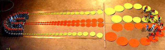
Het eerste probleem hier is natuurlijk het feit dat op grond van het gebruik
van gedekte pijpen, de afstraling van het geluid sterk gelokaliseerd is ter
hoogte van de labia van de pijpen. Hierdoor kan een uiterst kompakte opstelling
van de pijpen in meer dan twee rijen niet doorgevoerd worden.
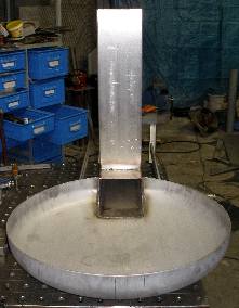
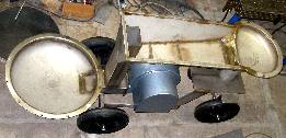
- 19.03.2006: Opmaak bestelbon voor Demar Lux (inox). Lay out alternatief
voor de pijpopstelling: twee cirkels: 400mm en 600mm doorsnede verbonden door
een licht kegelvormig middendeel. Inventarisatie van de benodigde ventielmagneten.
Het kostenplaatje alleen voor de ventielen beloopt zo'n 3800 Euro.
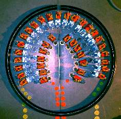

De onderkanten van de beide ronde gedeelten kunnen worden vervaardigd met holle
bodems in standaard afmetingen, inox 304L of 316, 3mm dikte.
- 21.03.2006: Hout voor de bovenplaat van de windlade besteld. Uiteindelijk
opteerden we voor een tropische (afrikaanse) houtsoort. De levertijd blijkt
behoorlijk lang te zijn...
- 23.03.2006: labowerk: metingen aan optocouplers voor de midi data ingang.
Het 6N137 type blijkt bij een ingangsstroom doorheen de LED van 5mA ruimschoots
sneller dan de 6N138. Pin 7 blijft onverbonden en pin 6 krijgt een weerstandje
van 280 Ohm naar de +5 voeding. Een 1MHz blokpuls verschijnt met behoud van
de symmetrie goed op de uitgang. De datasheet garandeert Baudrates tot 100kB.
Noteer dat de stroom in de midi standaard in 1983 werd vastgelegd en bepaald
op 5mA.
- 04.04.2006: soldeerwerk testschakeling met pulse en hold.
- 12.04.2006: pulse-hold board ontwerp nagezien. Nu per board goed voor 14
noten.
- 13.04.2006: levering elektromagneetkleppen vemtielen August Laukhuff.
- 22.04.2006: levering inox demar lux: flenzen en boorden 700mm en 500mm..
- 26.04.2006: nogmaals geinformeerd naar levering hout voor bovenkant windlade...
- 04.05.2006: werkplan TIG laswerk aan onderzijde windlade.
- 11.05.2006: mail naar Laukhuff i.v.m. levertermijn kompressor.
- 12.05.2006: Start TIG laswerk en assemblage windlade.
- 17.05.2006: kompressor zou morgen moeten geleverd worden... Betaling o.k.:
1700 Euro....
- 18.05.2006: de naar onze specifikaties bestelde kompressor is geleverd,
getest en goed bevonden: 0.45 Pk, 230/400 V, 1.5/0.9 A - 2800 rpm @ 50 Hz.
Debiet 8 kubieke meter per minuut bij 120 mm H2O druk.
- 19.05.2006: metingen motorkarakteristieken en bepaling van de specifikaties
voor de te gebruiken motorcontroller.
- 22.05.2006: Het pijpwerk voor de eerste 120 pijpen is klaar in het atelier
van Ghislain Potvlieghe. Draaiwerk hoofdassen: resp. 700 mm en 500 mm, dikte
25 mm, in gehard inox.
- 23.05.2006: start uittekenen lasplan onderstel en wielbasis. Levering hout
voor bovenkant windlade: Wawa hout (obeche, of met de latijnse benaming triplochiton
scleroxylon) uit Afrika. Het is een betrekkelijk lichte en ook lichtgekleurde
houtsoort die uitermate geschikt is voor houtsnijwerk. Kostprijs hout: 180
Euro. Bodemplaat (AISI 304L, 150x310x8, voor montage motor gesneden en geboord.
Motor montage met M6 trillingsdempers.
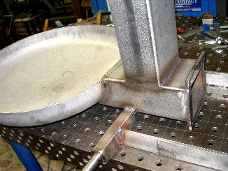
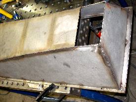
- 24.05.2006: Uitvoering lasplan volgens technische tekening
De in oranje ingekleurde delen stellen het wawa-houten bovenblad van de windlade
voor. De motor projektie is in het blauw aangegeven. Uitgevoerd: plasma snijwerk
verbinding voorste holle bodem met 150x100x3 inox kokerprofiel evenals TIG
laswerk van beide komponenten. Laswerk motor flens uitgevoerd in 15 x 10 x
150 inox met voorgeboorde bevestigingsgaten voor M5. Draaiwerk assen met eind
sleuven voor omega ringen.
- 25.05.2006: Laswerk draaiwielstel achterstuk. Draagchassis motor en motorflens
gelast. Kokerprofiel 150x100x3 vertikaal uitgesneden en dichtgelast. Voorste
as definitief gepositioneerd en afgelast. Motor moet met een 4mm dikke rubber
of neopreen dichting gemonteerd worden op de flens (trilvrij!). Onderkant
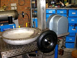
chassis afgelast. Werkfotos gemaakt
- 26.05.2006: Laswerk kraagflens op voorste holle bodem. Rondom gelast aan
de binnenzijde. Inpassen kompressor in chassis.
- 27.05.2006: Proefmontage houtwerk voor de 24 voorste pijpen (laagste oktaaf)
op flens en passing met dichtingsspanring voorzien van 12 lange M6 bouten.
Dichtingstest met kruipolie op laswerk. De vertikale as waarmee het achterwielstel
onder het chassis draait, kan worden gemaakt uit een inox M24 binnenzeskant
cilinderschroef. Eventueel kan hier een kogellager geplaatst worden. Het horizontaal
glijden kan worden verzekerd met een teflon ring.
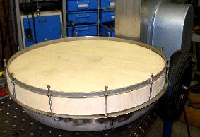
- 28.05.2006: Foto wawa hout op frontale windlade en gezaagd en geschaafd
hout voor de bovenste windlade. De gaten kunnen slechts geboord, gezaagd en
gehoond worden wanneer de pijpen hier afgeleverd zijn. Eerste voorlopige afdichting
frontale windlade met neopreen.

- 29.05.2006: Nieuwe bepaling dispositie van de pijpen op de windlade. Voorste
windlade: 24 pijpen (1 oktaaf). Cirkelsegment in bovenlade krijgt 48 pijpen
( de hoogste twee oktaven en dus de kleinste pijpen, voor de noten 84 tot
108. De minimale afstand tussen de pijpen onderling wordt in dit gebied volledig
bepaald door de afmetingen van de magneetventielen en niet door de diameters
van de pijpen zelf). Het rechthoekig gedeelte van de bovenste windlade krijgt
dan de resterende 60 pijpen in een vier-rijige opstelling. De opstelling van
de pijpen levert wel een ontwerp dilemna op: wanneer we de pijpen van de 440Hz
diapason reeks aan een kant opstellen en de kwarttoonspijpen aan de andere
kant, dan ontstaat er een assymetrie in de klankprojektie wanneer het instrument
niet centraal wordt opgesteld, maar bvb. tegen een wand. Wanneer we de pijpen
in oplopende volgorde van toonhoogte opstellen dan zullen deze dynamische
onregelmatigheden van toon tot toon opleveren. Alleen bij een lineaire opstelling
zou dit kunnen vermeden worden, maar dan zou het instrument een lengte moeten
krijgen van bijna zes meter... Een dringend noodzakelijk experimenteel onderzoek
dringt zich trouwens op n.a.v. de bepaling van de minimale afstand tussen
de pijpen. Het is duidelijk dat een te dichte plaatsing de vlotte toonopwekking
en ook de stemming in het gedrang kan brengen. De labia van de pijpen zouden
op teoretische gronden minstens een kwartgolflengte van elkaar (of eender
welk ander obstakel) moeten verwijderd zijn.
- 30.05.2006: Extra ventielen besteld bij Laukhuff: polstermaten 35mm, 30mm
em 25mm ontbraken voor een regelmatige overgang tussen de maten van de pijpvoeten.
Materiaal- en onderdelenlijst toegevoegd aan bouwverslag in funktie van onderhoud
en technische dokumentatie.
- 31.05.2006: Herberekening en konstruktie vertikale achterwielstel as zo
dat de draaicirkel ten volle 90 graden kan zijn. Verbindingsstuk tussen oplegger
(300 x 10 x 450) en voorste deel van het chassis onder 60 graden. M24 x100
cilinderkop inbus bouten en moeren, evenals bijhorende schotelveren in inox
besteld.
- 01.06.2006: Verder las- en plasmasnijwerk. Schuine opstand stukken 60 graden
gesneden en gelast. Nieuwe, vervolledigde tekening van het frontaal aanzicht
gemaakt:. De ruimte tussen de bovenste windlade en het achterwielstel is voorbehouden
voor de besturingselektronika.
- 02.06.2006: Extra ventielen Laukhuff geleverd. Eerste positionering voorste
gedeelte chassis tegenover achterdeel. Natrekken van alle ontwerpmaten in
de reeds gelaste konstruktie. Vanaf nu moeten alle positioneringen met takels
gebeuren. Uittekenen bouwplan voor de bovenste windlade. Alles uit te voeren
in inox plaat AISI304L, dikte 3mm.

- 03.06.2006: Start laswerk aan bovenste windlade. Legframe voor houten pijpdrager
uit inox 25x10 staaf, uitgefreesd voor passing in inox boordrand, dikte 3mm.
Boorwerk spangaten voor luchtdichte afsluiting.
- 04.06.2006: Plasmasnijwerk bovenste windlade, opstanden. Aanmaak plooimallen.
Uitzetten snijstukken. Plaatslagwerk hoekstukken. Dichtlassen naden.
De konstruktie moet nog spanningsvrij gemaakt worden! Bij gebrek aan oven,
zal dit met een gasvlam moeten gebeuren... (Acetyleen brander)..
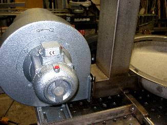
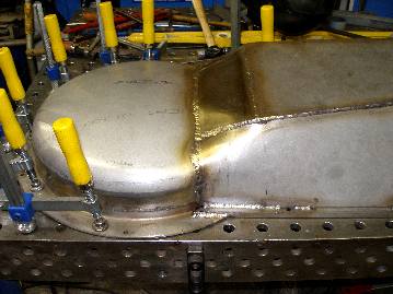
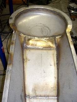
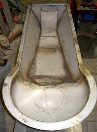
 05.06.2006:
eerste voorlopige assemblage van het gehele chassis. De hoogteligging van
de bovenwindlade tegenover de onderste windlade is op de foto nog niet bepaald.
Begin uitsnijden kleppen voor de tremulant. Hiervoor moeten nog praktische
proeven worden opgezet, meer bepaald m.b.t. benodigde krachten en windafdichting
van de assen.
05.06.2006:
eerste voorlopige assemblage van het gehele chassis. De hoogteligging van
de bovenwindlade tegenover de onderste windlade is op de foto nog niet bepaald.
Begin uitsnijden kleppen voor de tremulant. Hiervoor moeten nog praktische
proeven worden opgezet, meer bepaald m.b.t. benodigde krachten en windafdichting
van de assen.- 06.06.2006: Proefkonstruktie windklep met stappenmotorbesturing.. As 6mm,
voor de afdichting moeten gasdichte kogellagers worden gebruikt. De overbrenging
naar de motor kan via een gekartelde riemschijf gebeuren. Een positiesensor
zal nodig blijken in deze aanpak. De bevestiging van de klep op de as is bijzonder
moeilijk uit te voeren.
- 07.06.2006: M24 bouten geleverd. Grootste sterkteklasse (DIN912). Deze kosten
zomaar eventjes 50 Euro per stuk... M2 inox boutjes ingekocht voor montage
klep op as. Kogellagers voor as: FAG 626.2RS, asmaat 6mm, buitenmaat 19mm
in een gasdichte uitvoering. Hele dag gewerkt aan zuiver slijpen van de klepzitting
en het balanceren van de as met gemonteerde klep.
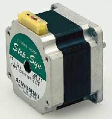
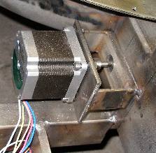
- 08.06.2006: Opzoekwerk naar geschikte stappenmotoren en bijhorende kontrollers.
Alvast bij Farnell van Sanyo Denki, type 103H7123-0440/1 besteld voor evaluatie.
(ca. 90 Euro per stuk). De bijhorende kontrollers kosten 250 Euro per stuk.
Konstruktie bevestigingsflenzen voor de kogellagers van de tremulanten / windkleppen.
(uit inox plaat 8mm dik, gat 19.0mm, gehoond). Opzoekwerk naar een geschikte
positiesensor voor montage op de 6mm as. De Sanyo steppers zien eruit als
op de foto hierbij:
- 09.06.2006: Konstruktie tweede windklep voor montage in de kondukten van
de bovenste windlade. Opzoekwerk naar datasheets voor de motorcontrollers
van Sanyo Denko, ze werden niet bijgeleverd... Berekening extra voedingsbehoeften
24/36V supply. Schema uitgetekend voor het PIC board nodig voor de besturing
van de motorcontrollers. De pulse inputs cw en cww moeten een blokgolf krijgen
met duty cycle van niet meer dan 50% en een minimale pulsbreedte van 20 microsekonden.
De maximale frekwentie is 20kHz, voor een toerental van 3000 rpm.. Dat is
in elk geval ver boven het maximaal wenselijke in deze tremulant toepassing.
16Hz of, 960 rpm is ons maximum, maar aangezien de klep bij elke omwenteling
de luchtstroom tweemaal onderbreekt, moeten we de helft hiervan nemen als
maximum, dus 480 rpm, of een pulse frekwentie kleiner dan 3.2kHz (in full-step
bedrijf). Het power down signaal maakt de motor stroomloos. Bij logisch 0
op de input gebeurt dit. De step angle input laat de motor in half-stap modus
draaien wanneer het logisch nivo 0 is. Wanneer het 1 is draait de motor in
vol-stap modus. In onze toepassing is vol-stap modus aangewezen en hoeft de
PIC dit signaal dus niet te sturen..
- 14.06.2006: Pijpen voor <Qt> allemaal afgeleverd door Ghislain Potvlieghe.
Nu kunnen we de gaten in de windlade boren en frezen.. Het stemmen en intoneren
moet later gebeuren. Daarna pas kunnen de pijpdeksels allemaal dichtgesoldeerd
worden. De uiteindelijk gebruikte legering bestaan uit 95% tin, 4% antimoon
en 1% koper.

- 15.06.2006: Overleg met Johannes Taelman m.b.t. de stappenmotor sturing
van de kleppen en tremulanten. Bespreking van de toe te passen positiesensortechnologie.
- 16.06.2006: Uittekenen boorplan voor de onderste windlade uitgaand van de
werkelijke maten van de pijpvoeten in het onderste oktaaf. Levering inox schotelveren
voor montage achterwielstel (kostprijs 334 Euro!). Specifikatie en bestelling
hoofdschakelaar bij Holderbeke.
- 17.06.2006: Konstruktie inox draagbrug voor onderste stappenmotor windlade.
Uitlijning assen windklep en motor. Aanmaak askoppeling 6mm -> 1/4"
motor as.
 18.06.2006:
nameten pijpen en definitieve bepaling van het hoogteverschil tussen beide
windladen: 600mm. (640mm is de hoogste mogelijkheid). Vast- en gasdicht lassen
van de bovenste windlade aan de windinlaat-kolom uit kokerprofiel 100x150.
Laswerk draagbeugel voor de stappenmotor van de bovenste windlade. Eerste
proefmontage en voorlopige uitlijning van de assen. Als asverbinding passen
we hier een 15mm Spinax elastische koppeling toe. Dit moet ook het bijgeluid
verbonden aan stappenmotoren wat dempen.
18.06.2006:
nameten pijpen en definitieve bepaling van het hoogteverschil tussen beide
windladen: 600mm. (640mm is de hoogste mogelijkheid). Vast- en gasdicht lassen
van de bovenste windlade aan de windinlaat-kolom uit kokerprofiel 100x150.
Laswerk draagbeugel voor de stappenmotor van de bovenste windlade. Eerste
proefmontage en voorlopige uitlijning van de assen. Als asverbinding passen
we hier een 15mm Spinax elastische koppeling toe. Dit moet ook het bijgeluid
verbonden aan stappenmotoren wat dempen.- 19.06.2006: Verder werk aan de windklep voor de bovenste windlade. Korrektie
van de nodige vooropening van de klep en uitlijning van de as. Om loskomen
van de drie boutjes waarmee de klep op de as vastzit te voorkomen, moet die
as op de klep worden gekleefd met silikonenrubber. (Loctite blue). Flens van
het tegenlager voor de bovenste motor vastgelast Spinax koppeling in spuitgiet
aluminium met cyaanakrylaat gelijmd op de assen. Tweede Spinax askoppeling
besteld bij MEA.
- 20.06.2006: Montage manometer op de vertikale kondukt, voor de windkleppen
en tremulanten. De drukoverbrenging is zijdelings via een aangelaste haakse
bocht. Hoewel de bocht een diameter heeft van 25mm, is het luchtgat in de
koker toch slechts op 10mm uitgeboord. De manometer heeft een gevoeligheid
van 25 mBar (250 mm H2O). Schaaldiameter 100 mm. De
behuizing is geheel in roestvast staal. De bevestiging van de (afgevijlde)
1/2" messing schroefdraad in het inox bochtstuk werd gemaakt met silikonenrubber.
Gezien de erg lage druk is daarbij geen enkel gevaar voor lekken. Ook de hechting
van de achterwand van de manometer op de vertikale kolom werd uitgevoerd met
hetzelfde materiaal. Indien ooit vervanging nodig zou zijn, moet dit met een
paletmes gebeuren. De manometer werd aan de motorzijde van de kompressor geplaatst,
naast de motorkontroller, waardoor de elektronische afregeling en het programmeren
van de kontroller wordt vereenvoudigd. (Bij <Krum>
hadden we ze elk aan een andere zijde geplaatst, wat erg onkomfortabel bleek...)
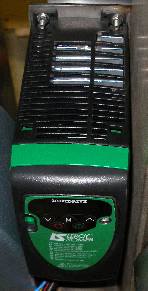
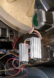 21.06.2006: Konstruktie draagbruggen voor de Sanyo motorkontrollers. Geplooid
uit inox 30x3 , beugelbreedte 100mm, opstand aan beide zijden 20mm. Montagegaten:
4mm. Draagplaat voor de kompressormotorkontroller (Leroy Somer) gesneden,
geboord (4mm) en aangelast aan de vertikale kondukt. Studie van de plaatsingsmogelijkheden
voor de diverse voedingseenheden. Bedrading kompressormotor in driehoeksschakeling.
Eerste plaatsing Sanyo motorkontrollers. De stappenmotoren, in full-step bedrijf
draaien 1.8 graden per stap. Voor 90 graden zijn dus 50 stapjes nodig. Elke
puls moet minstens 20microsekonden duren, duty cycle 50%, dus in totaal 40
microsekonden per stap. De teoretisch maximaal haalbare snelheid voor een
hoek van 90 graden (open/toe trajekt) is dan ook 2 ms..... Dit cijfer kan
natuurlijk in onze toepassing niet worden gehaald.. De wrijving op de as,
de winddruk zelf, en de eigenmassa van de windklep veroorzaken uiteraard een
inertie waardoor de motor nooit met een dergelijke snelheid kan opstarten.
Indien de motor teveel bijgeluiden zou veroorzaken, moet overwogen worden
mikrostap modus te gebruiken, ook al gaat dit ten nadele van de maximaal haalbare
kracht. De kracht op de windklep is maximaal wanneer deze in de gesloten stand
staat en de andere zijde onbelast is, een omstandigheid die zich alleen kan
voordoen bij het spelen van volledige klusters op het instrument, en dan nog
voor zover we het maximale debiet van de kompressor (8m3 / min) niet overschrijden.
Immers in dit laatste geval, zakt automatisch de geleverde druk. De worst
case kracht op de gesloten klep bij een winddruk van 100mmH20
(= 10mB = 1kPa = 1000N/m2) is, wanneer we de oppervlakte van de klep berekenen
als 100mmx150mm = 1.5dm2, 15Newton. De kracht versus snelheid kurves van de
fabrikant (Sanyo) voor de motor kontroller en stappenmotor kombinatie zoals
hier toegepast, zien eruit als:
21.06.2006: Konstruktie draagbruggen voor de Sanyo motorkontrollers. Geplooid
uit inox 30x3 , beugelbreedte 100mm, opstand aan beide zijden 20mm. Montagegaten:
4mm. Draagplaat voor de kompressormotorkontroller (Leroy Somer) gesneden,
geboord (4mm) en aangelast aan de vertikale kondukt. Studie van de plaatsingsmogelijkheden
voor de diverse voedingseenheden. Bedrading kompressormotor in driehoeksschakeling.
Eerste plaatsing Sanyo motorkontrollers. De stappenmotoren, in full-step bedrijf
draaien 1.8 graden per stap. Voor 90 graden zijn dus 50 stapjes nodig. Elke
puls moet minstens 20microsekonden duren, duty cycle 50%, dus in totaal 40
microsekonden per stap. De teoretisch maximaal haalbare snelheid voor een
hoek van 90 graden (open/toe trajekt) is dan ook 2 ms..... Dit cijfer kan
natuurlijk in onze toepassing niet worden gehaald.. De wrijving op de as,
de winddruk zelf, en de eigenmassa van de windklep veroorzaken uiteraard een
inertie waardoor de motor nooit met een dergelijke snelheid kan opstarten.
Indien de motor teveel bijgeluiden zou veroorzaken, moet overwogen worden
mikrostap modus te gebruiken, ook al gaat dit ten nadele van de maximaal haalbare
kracht. De kracht op de windklep is maximaal wanneer deze in de gesloten stand
staat en de andere zijde onbelast is, een omstandigheid die zich alleen kan
voordoen bij het spelen van volledige klusters op het instrument, en dan nog
voor zover we het maximale debiet van de kompressor (8m3 / min) niet overschrijden.
Immers in dit laatste geval, zakt automatisch de geleverde druk. De worst
case kracht op de gesloten klep bij een winddruk van 100mmH20
(= 10mB = 1kPa = 1000N/m2) is, wanneer we de oppervlakte van de klep berekenen
als 100mmx150mm = 1.5dm2, 15Newton. De kracht versus snelheid kurves van de
fabrikant (Sanyo) voor de motor kontroller en stappenmotor kombinatie zoals
hier toegepast, zien eruit als:
Het moge duidelijk zijn dat de rotatie frekwentie, voorzover we het maximaal
koppel nodig zouden hebben, zeker niet groter zal mogen zijn dan 4 Hz, wat
een tremulant frekwentie oplevert van ca.. 8 Hz. Indien haalbaar op PIC-kode
nivo zullen we wel pogen versnellingstabellen te gebruiken, om deze snelheden
zeker te kunnen halen en misschien te overschrijden.- 22.06.2006: Test stappenmotor bestuurde windkleppen. Voedingseenheid: Siemens
24V/20A Zoals te verwachten was, treden bij bepaalde pulsfrekwenties sterke
hoorbare resonanties op. Lage toerentallen blijken trouwens meer storingsgeluiden
op te leveren dan de hoogst haalbare. Uiteraard zullen deze later sterk worden
gedempt vanzodra de windlade op de inox konstruktie wordt gespannen. Kleppen
vastgezet en trillingsvrij gemaakt met Loctite Silicone Blauw (5926). Lagerhouders
definitief gepositioneerd en vastgelast. Lagers in flenzen gefixeerd met Loctite
638.
- 23.06.2006: Konstruktie nokkenschakelaar en 3-prong EEC netingang voor de
netspanningsvoorziening. De behuizing van deze schakelaar is tevens verdeeldoos
voor de verschillende komponenten die rechtstreeks netspanning nodig hebben.
Op deze schakelaar voorzien we eveneens een felrode verklikker.
 24.06.2006: Bouw 5 V / 5 A voeding voor alle TTL schakelingen en de PIC boards.
Voor de transfo gebruikten we een oud militair in olie ingegoten exemplaar
uit de jaren '60. De regeling is erg rechtoe- rechtaan en maakt gebruik van
twee 78K05 regulators (2 A/ stuk). Een van de geregelde uitgangen gaat naar
de stappenmotor kontrollers (elk vraagt 500 mA). De aansluiting gebeurt met
gewone banaanstekkers (4 mm, Hirschmann). De gehele voeding werd in, en deels
buiten (koelprofiel en transfo), een spuitgiet aluminium BIM box gemonteerd.
De module wordt naast een van de voorwielen op een gelaste inox drager gemonteerd.
Alle onderdelen werden omwille van de trilvastheid met exopy (Araldite) of
blauwe silikonen vast gezet in het chassis. Het schema toont de opbouw van
de analoge voeding evenals de zes blauwe led's die vanuit het midihub board
kunnen worden geschakeld onder MIDI kontrole. Opname exakte pijpmaten door
Sebastian Bradt. Bij inventariering blijken nog 24 pijpen te ontbreken, met
name die voor het zesde en hoogste oktaaf (96.5-108)
24.06.2006: Bouw 5 V / 5 A voeding voor alle TTL schakelingen en de PIC boards.
Voor de transfo gebruikten we een oud militair in olie ingegoten exemplaar
uit de jaren '60. De regeling is erg rechtoe- rechtaan en maakt gebruik van
twee 78K05 regulators (2 A/ stuk). Een van de geregelde uitgangen gaat naar
de stappenmotor kontrollers (elk vraagt 500 mA). De aansluiting gebeurt met
gewone banaanstekkers (4 mm, Hirschmann). De gehele voeding werd in, en deels
buiten (koelprofiel en transfo), een spuitgiet aluminium BIM box gemonteerd.
De module wordt naast een van de voorwielen op een gelaste inox drager gemonteerd.
Alle onderdelen werden omwille van de trilvastheid met exopy (Araldite) of
blauwe silikonen vast gezet in het chassis. Het schema toont de opbouw van
de analoge voeding evenals de zes blauwe led's die vanuit het midihub board
kunnen worden geschakeld onder MIDI kontrole. Opname exakte pijpmaten door
Sebastian Bradt. Bij inventariering blijken nog 24 pijpen te ontbreken, met
name die voor het zesde en hoogste oktaaf (96.5-108)- 25.06.2006: Montage Siemens SITOP 24 V/ 20 A voeding. De vereiste DIN rail
werd op een inox staaf 30x10 gemonteerd met 4 M4 boutjes. De inox staaf zelf
werd vastgelast in het chassis. Op deze staaf lasten we 2 voorgeboorde draagplaatjes
voor 50 mm LED of halogeen spotlites. Deze spotjes worden in serie geschakeld
en werken dan op 24 V. De stappenmotoren hebben een worst case stroomverbruik
van 2x3A=6A terwijl de stroombehoefte voor de velo-pulsen maximaal 6.5A beloopt.
De vermogensreserve (7.5A) staat ter beschikking voor verder nog toe te voegen
ingebouwde lichteffekten.
Eerste voorlopige opmeting en uittekening van de boormal voor de pijpen op
de onderste windlade.
- 26.06.2006: Opstelling PIC specifikaties voor de stappenmotorbesturing op
grond van het tijddiagram hieronder:
Boren van de gaten voor de pijpvoeten in de cirkelvormige windlade voor de
laagste 24 pijpen. Boormaat (voor het honen) 22 mm, behalve pijp 36.5 waarvoor
het gat werd uitgeboord op 26.5 mm. Eerste proefopstelling van pijpen. Een
mechanische versteviging aan de bovenzijde van de pijpen lijkt wenselijk,
met het oog op veilige transporteerbaarheid. Gaten geboord in de onderwindlade.
Boormaat 22 mm, behalve het gat voor pijp 36.5, dat werd uitgeboord op 26.5mm.
Na het boren werden de gaten geschuurd en gehoond tot een precieze passing
van de pijpen werd verkregen.
- 27.06.2006: Overlegvergadering met Ghislain Potvlieghe: mensurering van
de 25 pijpen in het hoogste oktaaf. Hierbij wordt overwogen deze als open
pijpen uit te voeren. Immers, voor gesloten pijpen zou de eerste spektraalkomponent
dan op 6.6kHz ligen (duodecieme op noot 97) en voor de hoogste pijp (108)
op 12.5 kHz. Voor open pijpen echter op 4.4 kHz en 8.3 kHz, gevolgd door de
eerder vermelde spektraal komponenten. Het is onwaarschijnlijk dat we het
verschil als een breuk in de kontinuiteit van de klankleur zullen kunnen waarnemen.
Uitgewerkte PIC specifikatie voor de midihub-board PIC ter verifikatie bezorgd
aan Johannes Taelman. Extra kettingtakels aangeschaft voor verdere montage
van Qt.
- 28.06.2006: Schikking van de pijpen op de lage windlade definitief en gedokumenteerd,
ten behoeve van de stemmers en onderhoud. Op de tekening werd ook de schikking
van de elektromagneten aan de binnenkant aangeduid. Begin montage van de elektromagnetische
ventielen op deze windlade. Voor de pijpen/noten 36-41.5 worden Laukhuff ventielen
type 3007 08, met een doorsnede van de zitting van 35mm gebruikt. Voor de
noten 42 tot 47.5, zittingen met een doorsnede van 30mm.
 De
afdichting van de zittingen werd uitgevoerd met sintetisch kalopel. De spoelen
worden trilvrij gemonteerd met tussenvoeging van 2 M4 moeren op een kussentje
uit Loctite blue siliconen. De bevestiging op het hout van de windlade wordt
uitgevoerd met voor elk ventiel twee 3 mm x 30 mm PZD kruiskop houtschroeven.
Gezien de zachtheid van het wawa hout, bleek voorboren overbodig en konden
we volstaan met het inprikken van het centergat met een els.
De
afdichting van de zittingen werd uitgevoerd met sintetisch kalopel. De spoelen
worden trilvrij gemonteerd met tussenvoeging van 2 M4 moeren op een kussentje
uit Loctite blue siliconen. De bevestiging op het hout van de windlade wordt
uitgevoerd met voor elk ventiel twee 3 mm x 30 mm PZD kruiskop houtschroeven.
Gezien de zachtheid van het wawa hout, bleek voorboren overbodig en konden
we volstaan met het inprikken van het centergat met een els.
- 29.06.2006: Afwerking ventielplaatsing onderste windlade. Test op lekken
met lichtbron. Eerste afregeling van de klepzittingen. Verwijdering van de
VDR weerstanden en de gele gekrulde aansluitsnoertjes.De VDR weerstanden spreken
immers de funktionaliteit van onze velocity sturing, waarvoor een vijfvoudige
overspanning wordt gebruikt, tegen. Soldering van de kleurgekodeerde aansluitdraden.
Regenboog kode: noot 36 = zwart, 37= bruin, 38- rood, 39= oranje, 40= geel,
41= groen, 43= blauw, 44= violet, 45= grijs, 46= wit, 47= zwart. De kwarttoonventielen
hebben dezelfde kleurkode, maar worden als een afzonderlijke kabelbundel behandeld
en naar buiten gevoerd doorheen een extra 13mm gat in de bovenplank van de
windlade.
- 30.06.2006: Bedrading onderste windlade.
 Aanmaak
kabel boom en doorvoer doorheen windlade. Boren 20mm gaten voor plaatsing
quad blue LED dekoratie lampen. Bestelling van de daarvoor bestemde lampes
(Philips, 24V 0.5W). Inkoop porcelijnen lampvoetjes met extra lange aansluitdraden
voor de blauwe LED spots op het chassis. Levering van de 24 hoogste pijpjes
voor de noten 96-108. Bestelling 2 Sitop voedingen 24V/ 10A voor rail montage.
Er stak een elektrische ontwerpfout in ons eerste idee om met een enkele 24V/20A
te kunnen volstaan: de 24V voor de velo-pulsen moet immers de positieve pool
aan massa hebben, wat diametraal staat tegenover de eisen gesteld door de
stappenmotorkontroller.
Aanmaak
kabel boom en doorvoer doorheen windlade. Boren 20mm gaten voor plaatsing
quad blue LED dekoratie lampen. Bestelling van de daarvoor bestemde lampes
(Philips, 24V 0.5W). Inkoop porcelijnen lampvoetjes met extra lange aansluitdraden
voor de blauwe LED spots op het chassis. Levering van de 24 hoogste pijpjes
voor de noten 96-108. Bestelling 2 Sitop voedingen 24V/ 10A voor rail montage.
Er stak een elektrische ontwerpfout in ons eerste idee om met een enkele 24V/20A
te kunnen volstaan: de 24V voor de velo-pulsen moet immers de positieve pool
aan massa hebben, wat diametraal staat tegenover de eisen gesteld door de
stappenmotorkontroller.
- 01.07.2006: Konstruktie poten binnenzijde windlade, nodig voor de montage
enerzijds en voor het opmeten van het trajekt van de ventielen, die immers
ondersteboven moeten werken. De kracht uitgeoefend door het eigen gewicht
van de polsters moet in die positie afgetrokken worden van de aandrukkracht
van de sluitveer. De poten in de windlade werden gemaakt uit M10x120 inox
bouten, gehecht in het hout met Loctite blauwe siliconen. Indien nodig zijn
ze dus verwijderbaar door hard te trekken. Kabelgat met de bedrading langs
een zijde luchtdicht afgekit. Verder werk aan deze windlade ligt voorlopig
stil, tot de blauwe LED lampen geleverd zijn. Die moeten immers aan de binnenzijde
bedraad en afgedicht worden.
- 02.07.2006: Uittekenen op het werkstuk zelf van de exakte posities van de
pijpen voor de bovenste windlade, rekening houdend met de afmetingen van de
ventielen, de breedte van de boord en de projektie van de pijpen zelf. 18u
gewerkt aan het uitmeten en uittekenen... De boorplekken werden geprikt met
een els en met duimspijkers gemarkeerd. Om het overbrengen van de tekening
op de andere zijde van het werkstuk te vereenvoudigen, gaan we alle gaten
eerst voorboren met een 6mm boor, de kleinste maat die net lang genoeg is
om doorheen de dikte van het hout te geraken.
- 03.07.2006: Doorboren met 6mm van alle 120 gaten. Overtekenen werkplan op
de andere zijde van de bovenplank van de windlade. Uitboren van de pijpgaten
op een diepte van 45mm. Te gebruiken boormaten: 22mm [MK3] (voor de noten
48-76.5), 17mm [MK2] (voor de noten 77-84.5), 13.5mm [MK2] (voor de noten
85-108). Tegenboren van de luchtgaten ( 20mm diep) en de ventielzittingen
in kleinere boormaten: 16mm [MK2](voor de noten 48-53.5), 14mm [MK2](voor
54-59.5), 13.5mm [MK2] (voor 60-62.5), 13mm (voor 63-76.5), 11.5mm (voor 77-84.5)
en 10mm (voor 85-108). De ventielopeningen kunnen op deze wijze kleiner worden
genomen van de diameter van de pijpvoet. Bovendien kunnen de pijpen nu zonder
gevaar volledig diep op de windlade worden gezet. Nameten breedte van het
labium en opname van deze meetgegevens in de mensuurtabel.
- 04.07.2006: Proefplaatsing van de ventielen. Bepaling van de plaatsing van
de kabelboomdoorvoeren en de eventuele pijpbelichting. Inkoop Loctite siliconen
voor de plaatsing van de ventielen op de windlade. Inkoop: Houtschroeven 3.0
x 30, kruiskop, voor bevestiging ventielen. Monteren en afregelen van de 24
ventielen voor het hoogste oktaaf. (96-108) Montage zoals in de onderste windlade:
op 2 M4 moertjes ingekleefd met Loctite blauw.
- 05.07.2006: Montage en afregeling 24 ventielen voor de noten 84-95.5
 Berekening van de benodigde ruimte voor de plaatsing van de besturingsprinten.
Berekening van de schuine opstand naar de onderzijde van de schaal van de
hoge windlade. Dit verbindingsprofiel (30x50x3) wordt onder 60 graden geplaatst
en raakt het centrum van de achtercirkel van de bovenste windlade. Levering
van de tien bestelde blauwe quad-LED lampjes. Kost 350 Euro...
Berekening van de benodigde ruimte voor de plaatsing van de besturingsprinten.
Berekening van de schuine opstand naar de onderzijde van de schaal van de
hoge windlade. Dit verbindingsprofiel (30x50x3) wordt onder 60 graden geplaatst
en raakt het centrum van de achtercirkel van de bovenste windlade. Levering
van de tien bestelde blauwe quad-LED lampjes. Kost 350 Euro...
- 06.07.2006: Montage en afregeling ventielen 72-83.5. Plaatsing blauwe quad-LED's
van Philips op de onderste windlade. Volgieten van het overblijvende deel
van deze 20mm gaten met een mortel uit 50% epoxyhars en 50% zuiver wit kwartszand.
Op deze wijze kunnen de cilindervormige gaten alvast geen turbulenties en
sekondaire resonanties meer doen ontstaan in de windlade. Vanzelfsprekend
garandeert dit tevens ook een perfekte luchtdichte afsluiting. Aansluitdraden
lampjes aangesoldeerd op de soldeerlippen gemonteerd in het midden van de
binnenkant van de windlade. De dikke rode draad is de gemeenschappelijke positieve
pool van de 24V voeding, terwijl de zwarte draad de schakeldraad is voor de
lampjes aan de kromatische kant en de blauwe draad die voor de lampjes aan
de kwarttoonskant. Vastlassen van de schuine drager van de bovenste windlade.
Finalisatie van het printontwerp voor de kleppen sturingen met aanslaggevoeligheid.
(PIC boards)
- 07.07.2006: Uitgutsen en beitelen van de passing van de bovenwindlade op
het inox deel. Dit moet op een halve millimeter nauwkeurig gebeuren, zodat
de dichtingsband in neopreen een gelijkmatige druk uitoefent op alle plaatsen
van het hout. Zoniet bestaat immers gevaar op kromtrekken na verloop van tijd.
Bestelling bij Europrint van de twaalf nodige PC boards voor de ventielbesturing.
Levering extra spinax elastische askoppelingen voor de stappenmotoren door
MEA.
- 08.07.2006: Gladschuren van de passing met een schuurblok. Boren gaten voor
de drie quad-led's in de bovenste windlade evenals van de twee doorvoergaten
voor de kabelbomen (2 x 68 geleiders). Montage en eerste afregeling ventielen
60-71.5. Vast monteren met silicone-kit van de halogeen LED sockets onderaan.
(Inox M3 boutjes).
- 09.07.2006: Montage en eerste afregeling ventielen 48-59.5 op de bovenste
windlade. Ingieten met kwarts-epoxymortel van de LED-gaten. Meteen M8 oogbouten
voor de kabelgeleiding mee ingegoten. Solderen van de gemeenschappelijke positieve
voedingsaansluitingen van alle 121 ventielen.
- 10.07.2006: Bedrading nokkenschakelaar en voedingsspanningsvoorziening naar
alle komponenten.
 Plaatsing van de twee 24V Siemens Sitop voedingen op opgelaste DIN rail. Plaatsing
van de 12V/ 50A Sunpower SPS600-P12 voeding. Lassen van draagprofiel daarvoor.
Aanmaak kabelbundel voor de netspanningsvoerende bedrading. In de nokkenschakelaar
bouwden we meteen de enige nog overblijvende quad LED in, als monitor voor
de spanning. Werkvergadering met Johannes Taelman. Op zoek naar geschikte
Hall-effekt positiesensoren en data acquisitie chips voor de positionering
van de windkleppen. De Melexis MIX90316 geintegreerde Hall sensor met DSP
aan boord ziet er veelbelovend uit. (cfr.http://www.melexis.com )
Plaatsing van de twee 24V Siemens Sitop voedingen op opgelaste DIN rail. Plaatsing
van de 12V/ 50A Sunpower SPS600-P12 voeding. Lassen van draagprofiel daarvoor.
Aanmaak kabelbundel voor de netspanningsvoerende bedrading. In de nokkenschakelaar
bouwden we meteen de enige nog overblijvende quad LED in, als monitor voor
de spanning. Werkvergadering met Johannes Taelman. Op zoek naar geschikte
Hall-effekt positiesensoren en data acquisitie chips voor de positionering
van de windkleppen. De Melexis MIX90316 geintegreerde Hall sensor met DSP
aan boord ziet er veelbelovend uit. (cfr.http://www.melexis.com )
- 11.07.2006: Berekening toepasbaarheid van de Melexis draaipositie sensor..
Zoektocht naar geschikte lateraal gemagnetiseerde permanente magneten voorzien
van een gecenterd gat van 6mm. Bestelling regenboogkleurdraden bij Farnell.
Bedrading motorcontroller (kabelboom naar het midihub board).
- 12.07.2006: Levering kleurdraden Farnell. Start bedrading in regenboog draad
van alle ventielen op de bovenste windlade. Kleurkode bedrading: zwart = 48,
58, 68, 68, 88, 98, 108 in de kromatische bundel en eveneens zwart voor 48.5,
58.5, 68.5, 78.5, 88.5, 98.5 in de kwarttonenbundel. Ontwerp schakelingen
rond de positiesensor van Melexis (MLX90316). Bedradingsplan
opgesteld.
- 13.07.2006: Eerste elektrische test van het netspanningsgedeelte. De nokkenschakelaar
blijkt intern te knisperen en geeft ozon vrij... Eerste voorlopige programmering
van de motorkontroller. Eerste test van de motor: draairichting aangepast,
grondige smering uitgevoerd met syntetische olie. Zonder de windladen erop,
gaan de windkleppen vanzelf meedraaien en veroorzaken en spektakulair infrasoon
geluid.... Klaarblijkelijk zit het goed snor met hun lagering. Manometer blijkt
het ook goed te doen. Opstelling eerste volledige midi-implementatie tabel
in overleg met komponisten en gebruikers.
- 14.07.2006: Verdere uitwerking van de volledige bedradingstabellen voor
de windladen, met aangegeven van de gebruikte kleurkodering en de aansluitingen
van de Weidmuller konnektoren. Solderen draadbundel bruin voor de noten/ventielen
49, 49.5, 59, 59.5, 69, 69.5, 79, 79.5, 89, 89.5, 99, 99.5. Konstruktie draagpoten
voor omkering windlade. Aansluiting Weidmuller konnektor voor de kwarttonen
op de onderste windlade. Positionering van de de pijpen op de bovenste windlade
ziet eruit als:
- 15.07.2006: Lassen draagbeugels voor de velo/hold boards onder de windlade.
Inox 15 x 2 strip met inleg in 15 x 10. In deze beugels worden de polykarbonaat
dragers voor de gedrukte schakelingen opgehangen en vastgezet. Solderen draadbundel
bruin voor de noten/ventielen 50, 50.5, 60, 60.5, 70, 70.5, 80, 80.5, 90,
90.5, 101, 101.5. Inlassen L-profiel 30x30 voor de montage van de printen
voor de lage windlade op een stuk polykarbonaat. Uitsnijden print dragers
in polykarbonaat. Aansluiting Weidmueller konnektor voor de normale tonen
op de onderste windlade.
- 16.07.2006: Ontwerp draagstruktuur en voedingsrails voor de velo/hold boards..Aanlassen
draagprofielen voor het midihub board en en midi ingangskonnektors.Solderen
draadbundels rood en oranje voor de noten/ventielen 51 - 103
- 17.07.2006:Solderen draadbundels geel / groen/ blauw voor de noten/ventielen
52-53-54 -> 104,105,106. Elektrische test van alle ventielen in werkingspositie.
- 18.07.2006: Solderen draadbundels grijs/wit. Dichten kabelboomgaten.. Totaal
draadverbuik: 362m. Aansluiting Weidmueller konnektoren voor de kwarttoonspijpen
op de bovenste windlade. (Q-side). Zoektocht naar geschikte neopreen afdichtingsband.
- 19.07.2006: Bundeling Weidmueller konnektoren naar polykarbonaat montageplaat
voor de PC boards. Bedrading kabelboom stappenmotorkontrollers naar midihub
board. Levering PC boards van EuroCircuits.
- 20.07.2006: Aanmaak kabelbundels. Een bundel voor de normale kromatische
notenreeks, een andere voor de kwarttonen. Bestukking van de eerste testprint
voor de velo/hold besturing van de toonventielen. Inventarisatie van de nodige
onderdelen: nazicht voorraden. BS250's moeten zeker besteld worden. Het data
sheet staat in Philips Semiconductor Book SC07, 1994.
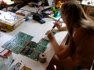
- 21.07.2006: Ontbrekende onderdelen besteld bij Farnell. Moniek Darge helpt
mee met het soldeerwerk van de twaalf velo/hold boards.
 Boards voor de besturing van de onderste windlade zo goed als afgewerkt. Polykarbonaat
drager daarvoor uitgeboord (4.1mm gaten voor messing M4 bouten) en voorzien
van roodkoperen voedingsrails.Draaien van de koperen verbindingsbussen op
de draaibank. BS250 is niet te vinden bij Farnell. Een alternatief type is
BSP254A, waarbij de A suffix belangrijk is want het gewone BSP254 type heeft
een andere pinning! Het moet in elk geval een P-channel enhancement mode vertical
D-MOS transistor type zijn.
Boards voor de besturing van de onderste windlade zo goed als afgewerkt. Polykarbonaat
drager daarvoor uitgeboord (4.1mm gaten voor messing M4 bouten) en voorzien
van roodkoperen voedingsrails.Draaien van de koperen verbindingsbussen op
de draaibank. BS250 is niet te vinden bij Farnell. Een alternatief type is
BSP254A, waarbij de A suffix belangrijk is want het gewone BSP254 type heeft
een andere pinning! Het moet in elk geval een P-channel enhancement mode vertical
D-MOS transistor type zijn.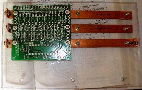
- 22.07.2006: Soldeerwerk PC boards velo/holds. We vallen zonder 4k7 weerstandjes...
Helaas zijn er geen nachtwinkels voor elektronika. Montage polykarbonaat paneel
onder de bovenste windlade. Uitzagen koperen spanningsrails voor de bovenste
windlade. Montage van de voedingsrails.
- 23.07.2006: verder soldeer- en bestukkingswerk van de printen: BY228, MUR4100
of SF52 diodes, BYV32-200 dubbeldiodes en IRL640 mosfets. Het einde van onze
mosfet voorraden is evenwel in zicht. Spanningsrails op de dragers bedraad
en aangesloten op de respektievelijke voedingen ( +12 V en -24 V). Hiervoor
gebruiken we messing M4 boutjes met rondellen eveneens uit messing.
- 24.07.2006: Solderen van alle Weidmuller konnektors en de 10 MHz kristallen
op de printen.. Levering onderdelen Farnell. Solderen door Moniek van alle
nog resterende 4k7 weerstanden en van de 40 polige IC voeten. Nieuwe bestelling
bij Farnell: extra PIC18F4620-I/P's, P-channel J-Fets BSP254A als alternatief
voor BS250. (TO92 behuizing met de gate centraal maar met een DIL-raster pootafstand
waardoor we ze een beetje moeten bijbuigen voor de montage)
- 25.07.2006: grondig nazicht van het kostenplaatje: dit beloopt nu al (zonder
inbegrip van lonen) meer dan 25.000 Euro. Levering Farnell. Vervolg soldeerwerk
aan de PC boards. Bedradingsplan voor de midi-signalen en de 5V voedingsspanningsvoorziening
uitgewerkt. De boards met labels Q1, K1, Q2, K2, Q6, K6 zijn al helemaal klaar.
Eerste test kode toegevoegd aan GMT in de speciale QT-module.
- 26.07.2006: Verder soldeerwerk voor de boards Q3, K4, Q4, K4, Q5 en K5.
In totaal reeds 504 mosfets ingesoldeerd... Montage door Moniek van buffer
tantaaltjes over de 5 V spanning als finishing touch. Definitieve montage
van de beide printen K1,Q1 voor de besturing van de onderste windlade.
- 27.07.2006: Alle boards op Qt zijn gemonteerd. Bedrading voor de 5 V voedingsspanning
en de midi inputs afgewerkt. De boards voor K1 en Q1 evenals K2 en Q2 krijgen
hun midi signalen van eenzelfde TTL output op het midi-hub board. Dit board
heeft immers slechts 10 midi TTL ouputs. Beide PIC's moeten dus geprogrammeerd
zijn vooraleer de spanning wordt aangezet, zoniet zijn de betreffende input
pins op de PIC immers niet gedefinieerd. Bij een volgende upgrade van het
ontwerp van deze PC boards zouden we dan ook best een FET of transistorbuffertje
voorzien. Dat opent de mogelijkheid om ook midi in en +5V via een Cu-busbar
aan te sluiten. Het wachten is nu op de ultieme test met de PIC software...
Het wachten is nu op Johannes...
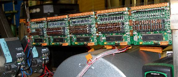
- 28.07.2006: Afwerking bedrading lampjes op beide windladen. De positieve
spanningslijn (+24V) is afzonderlijk losneembaar. Bij nameten van de voedingsrails
en de 5V lijnen blijkt een kortsluiting te bestaan tussen +5 en GND... Na
onderzoek blijkt de kortsluiting zich slechts voor te doen op die PC boards
waarop een PIC chip in het voetje werd geplaatst. Dan maar het datasheet en
de aansluitgegevens voor de 18F4620 er weer bijgehaald en nog eens goed vergeleken
met de layout van het PC-board... en jawel, wat blijkt: pinnen 31 en 32 zijn
verkeerdelijk omgewisseld waardoor Vdd aan Vss en vice versa is komen te liggen.
Deze pinnen staan dubbel op de chip waarbinnen een interne verbinding bestaat
tussen pin 11 en 32 enerzijds en pin 12 en 31 anderzijds. Het herstellen van
deze hardware bug is niet bepaald eenvoudig: aan pin 31, soldeerkant moet
aan beide kanten van het soldeereilandje het koper worden weggesneden dat
het eiland verbindt met het +5V vlak. Pin 32 moet aan de onderdelenkant losgesneden
worden van zijn verbinding met C8. Dan moet de verbinding van deze pin met
het massavlak onder de IC voet door, losgesneden worden. Hiervoor is een mini-steekbeiteltje
van 1mm breedte onontbeerlijk. Dan moet aan de soldeerzijde de pin met een
draadje verbonden worden met het +5V vlak. Nu kan pin 31 aan de onderdelenkant
onder de IC voet met een draadje aan het massavlak gesoldeerd worden. Tot
slot van de hele operatie moet een 100nF SMD kondensator worden gesoldeerd
tussen pin 31 en het +5V vlak, dit ter vervanging van C8. Deze bypass tussen
de pootjes van de PIC is essentieel voor een stabiele werking.
- 29.07.2006: Hardware debug/herstelling printen K1, Q1, K2, Q2. Demontage
en hermontage op het polykarbonaat bord. We zullen evenwel zonder 100nF SMD
kondensatoren vallen... Ontwikkeling PIC kode de 18F2525 PIC op het midi-hub
board met Johannes Taelman. Voor deze kode wordt gebruik gemaakt van de nieuwe
C kompiler van Microchip, dit terwijl we vroeger voor deze chips uitsluitend
assembler gebruikten. De performance-penalty zou onbetekenend zijn. Reeds
operationeel zijn nu: ctrl 7, kompressor motor speed, ctrl 66, motor on/off,
ctrl 8, dim-lites.. Met de besturing van de stappenmotoren zijn nog wat hardware
problemen: de pull ups moeten verlaagd worden tot 1k. (R8, R9) en 510 Ohm
(R15, R16 en de ongenummerde R's aan X16) op het hub board). De stijgtijd
van de door de PIC gegenereerde pulsen (nu ca.. 50us) was ca 15us, veel groter
dan de in het motorcontroller datasheet gespecifieerde 5us maximum in elk
geval. De verlaging van de pull ups tot 510 Ohm (0.25mW) moet dit met een
faktor 20 verbeteren. De dissipatie in deze weerstanden loopt nu wel op tot
50mW (10mA stroom bij 5V). Tweede programmeersessie met Johannes Taelman.
 Alle
voedingslijnen en spanningen nagemeten en getest. Testkode toegevoegd aan
GMT zodat we de tot nu toe geimplementeerde midi funkties ook onder software
besturing kunnen testen en evalueren. De tremulanten moeten onder midi ctrl.11
reeds kunnen draaien. Ook de kompressormotor besturing zou moeten werken.
Alle
voedingslijnen en spanningen nagemeten en getest. Testkode toegevoegd aan
GMT zodat we de tot nu toe geimplementeerde midi funkties ook onder software
besturing kunnen testen en evalueren. De tremulanten moeten onder midi ctrl.11
reeds kunnen draaien. Ook de kompressormotor besturing zou moeten werken.
- 30.07.2006: Hardware herstelling van de printen K3,Q3, K4, Q4. Korrektie
van de bug in de schemas voor de dokumentatie. De kompressor motor kontroller
blijkt niet steeds betrouwbaar te reageren op on/off kommando's. De spanning
op de betreffende pin schakelt slechts tussen 0 V en 10.2 V, wat marginaal
blijkt volgens het databook, waarin 10V als threshold wordt opgegeven. Daarom
de pull-up weerstand op het midihub board (R6) verkleind tot 1k5 middels een
1 W weerstand. Hierin dissiperen we nu immers maximaal 374 mW. Ook stak er
nog een bedradingsfout in het midihub board, waarop we een draadbrug vergeten
waren om de massa aansluiting van de mosfets voor de CW en CWW pulsen van
de tweede stappenmotorkontroller ook effektief met massa te verbinden. Testkode
in GMT verder up to date gemaakt.
- 31.07.2006: Laatste faze in elektronische mikrochirurgie op de boards van
Qt: de printen K5,K6, Q5,Q6 zijn nu ook helemaal in orde en vrij van kortsluitingen.
De worst case lekstroom naar aarde beloopt 10mA, wat duidelijk voelbaar is
op het chassis. We overwegen het EMC filter in de motor controller uit te
schakelen, dit reduceert de lekstroom tot 1 mA, weliswaar ten koste van heel
wat sterkere EMC emissie cijfers. De gemeten onbelaste spanning tussen reele
aarde en het chassis van Qt is 117 V (ac rms)... Toshiba laptop in orde gemaakt
en van de nieuwste GMT kode voorzien voor testopstelling van de reeds geimplementeerde
funkties.
- 01.08.2006: Een augustus.. Begin van de winter. De las en mechanika werken
kunnen weer ongehinderd door de warmte doorgaan. Ontwerp en uitwerking inox
drager voor schuine LED spots, te monteren links en rechts van de Siemens
Sitop 24 V voedingen. Inox plat 50x3x420.
 Boorgat
afstanden voor de halogeenlamphouders: 8 mm (draadgaten) en 12mm (M3 montagegaten,
voor M3 inbus inox boutjes). De porseleinen lamphouders worden trillingsvrij
vastgezet met Loctite blauwe silikonenlijm. Het inox profiel wordt voorzien
van afgeronde uiteinden (straal 25mm) haaks omgeplooid op 50mm van het uiteinde,
wat een goede mechanische beveiliging van de 50mm lampen oplevert. De beide
lampen worden in serie geschakeld en aangesloten op het licht-dim circuit
bestuurd door midi controller 8. Levering Farnell van de ontbrekende IRL640
power mosfets, extra BYV32 diodes en van de 3polige Weidmuller konnektors.
Werksessie met Johannes Taelman voor de ontwikkeling van de prototype kode
voor de velo/hold boards. Anders dan bij de kode voor de eerdere robots, die
immers geheel in assembler was geschreven, maken we deze keer gebruik van
de Microchip C-kompiler. Tot zover PIC's geprogrammeerd voor de K1 en Q1 boards.
De velocity kode heeft nog bugs. De aftertouch is voor later. All notes off
is nog niet geimplementeerd. Testkode toegevoegd in GMT. <Qt> produceert
zijn eerste -volkomen ontstemde en nog wat onstabiele - nootjes... Ontdekte
bugs: kanaal offset fout in K1-Q1. Lek op ventiel 46.5 (hardware). Velo nog
niet betrouwbaar. Kwa hardware wel o.k.: geen kortsluitingen.
Boorgat
afstanden voor de halogeenlamphouders: 8 mm (draadgaten) en 12mm (M3 montagegaten,
voor M3 inbus inox boutjes). De porseleinen lamphouders worden trillingsvrij
vastgezet met Loctite blauwe silikonenlijm. Het inox profiel wordt voorzien
van afgeronde uiteinden (straal 25mm) haaks omgeplooid op 50mm van het uiteinde,
wat een goede mechanische beveiliging van de 50mm lampen oplevert. De beide
lampen worden in serie geschakeld en aangesloten op het licht-dim circuit
bestuurd door midi controller 8. Levering Farnell van de ontbrekende IRL640
power mosfets, extra BYV32 diodes en van de 3polige Weidmuller konnektors.
Werksessie met Johannes Taelman voor de ontwikkeling van de prototype kode
voor de velo/hold boards. Anders dan bij de kode voor de eerdere robots, die
immers geheel in assembler was geschreven, maken we deze keer gebruik van
de Microchip C-kompiler. Tot zover PIC's geprogrammeerd voor de K1 en Q1 boards.
De velocity kode heeft nog bugs. De aftertouch is voor later. All notes off
is nog niet geimplementeerd. Testkode toegevoegd in GMT. <Qt> produceert
zijn eerste -volkomen ontstemde en nog wat onstabiele - nootjes... Ontdekte
bugs: kanaal offset fout in K1-Q1. Lek op ventiel 46.5 (hardware). Velo nog
niet betrouwbaar. Kwa hardware wel o.k.: geen kortsluitingen.
- 02.08.2006: Eerste opmeting midi-waarde, motor frekwentie, winddruk, met
nog niet afgedichte windlades.
| midi value for ctrl. 7 |
motor frequency |
air pressure in mm H20 |
| 127 |
40.0Hz |
80mm |
| 103 |
38.0Hz |
70mm |
| 77 |
35.0Hz |
60mm |
| 61 |
32.0Hz |
50mm |
Op grond hiervan en rekening houdend met het niet ten volle 10V dc bereik
van onze PWM analoge uitgang op de PIC, moeten we de motorkontoller zo programmeren
dat we wel degelijk 50Hz kunnen halen, en daarmee de maximale winddruk van
120mm. Dit vergt een herziening van parameter 2 op de Leroy controller. 65
Hz lijkt ons een goede testwaarde... Zoektocht naar geschikt geexpandeerd
neopreen afdichtingsband met gesloten celstruktuur. Uiteindelijk laten maken
op maat bij De Mulder (Zeeschipstraat, Gent).. Testsessie ventielen onderste
windlade.
- 03.08.2006: Laswerk stuurstang uit 30mm diameter, 2mm dikte inox buis. Voor
de bochten worden lasbochten gebruikt na mislukte pogingen om de buis te plooien
in onze Ridgid plooipomp. Wellicht hebben we niet de geschikte plooimallen.
30mm is immers geen standaard maat voor gas- of waterleidingsbuis. De 45 graden
hoeken werden uiteindelijk verkregen door een lasbocht in twee delen te zagen.
Winddichting van de bovenste windlade met MK-polymeerkit. Derde praktische
QT-werksessie met Johannes Taelman. Kode voor de velo/hold boards (K1,Q1)
nog steeds niet helemaal vrij van crashes... PIC kode voor de midihub pic
gewijzigd zodat we nu de tremulant motoren via ctrl 67 en 68 ook onafhankellijk
kunnen in- en uitschakelen. GMT testkode aangepast. Boards voor K5,K6, Q6
voorzien van PIC's: hier gebruiken we wel het low power type PIC18LF4620 in
40pins behuizing.
- 04.08.2006: Pijphouders terug weggenomen van de windladen na eerste tests
op afdichting. Om het op en afzetten van de pijpen iets komfortabeler te maken
konstrueerden we een karretje met vier zwenkwielen van 10cm. Alle kwarttoonspijpen
van de onderste windlade voorzien van een gegraveerde + markering in de exponent
van de noot. Begin inventarisatie van de nog lekkende kleppen. Op de lage
windlade is er alleen op klep 46.5 een lek. Klep 47 raakt de inox schaal.
We moeten dan ook erg precies zijn bij de eindmontage, al geeft het aanbrengen
van de winddichting ons wel ca. 2mm speelruimte. Voorlopige afdichting aangebracht
op de bovenste windlade. Zoniet halen we immers niet de gewenste einddruk
in de onderste windlade. Uitboren 6mm spangaten op inox schaal van de onderste
windlade. Spantest met hoepel.
- 05.08.2006: Onderste windlade definitief afgekit, alle ventielen lekvrij
gemaakt en trajekt afgeregeld.
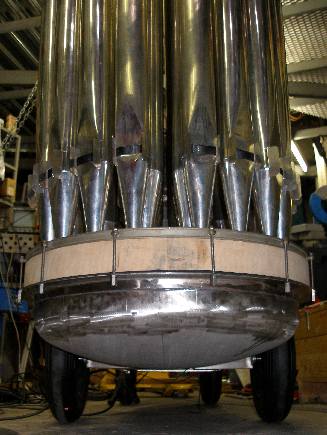 Terugslag
dempingsschroef met vilt afgeregeld op minimaal bijgeluid. Hoepel vastgezet
met inox M6x10 hex bouten en extra lange zeskant inox busmoeren aan de onderzijde.
Tochtband: rubber met gesloten cellen, 20mm breed, 10mm dik, zelfklevend,
vastgekleefd op de wawa-hout kant. Speeltests met K1, Q1 ontwikkeld in GMT.
Geen PIC crash kunnen veroorzaken. Wel is de default velocity scaling nog
niet goed. De pulsen zijn ongeveer een faktor 10 te lang. Overigens, bij velo=1
mag helemaal geen puls gegenereerd worden. Het doorlaat percentage van de
onderste tremulant klep blijkt toch wat te groot, al kunnen we het nog niet
echt goed testen. Wellicht mag het lek-debiet zeker niet groter zijn van de
luchtverbruik van een pijp.
Terugslag
dempingsschroef met vilt afgeregeld op minimaal bijgeluid. Hoepel vastgezet
met inox M6x10 hex bouten en extra lange zeskant inox busmoeren aan de onderzijde.
Tochtband: rubber met gesloten cellen, 20mm breed, 10mm dik, zelfklevend,
vastgekleefd op de wawa-hout kant. Speeltests met K1, Q1 ontwikkeld in GMT.
Geen PIC crash kunnen veroorzaken. Wel is de default velocity scaling nog
niet goed. De pulsen zijn ongeveer een faktor 10 te lang. Overigens, bij velo=1
mag helemaal geen puls gegenereerd worden. Het doorlaat percentage van de
onderste tremulant klep blijkt toch wat te groot, al kunnen we het nog niet
echt goed testen. Wellicht mag het lek-debiet zeker niet groter zijn van de
luchtverbruik van een pijp.
- 06.08.2006: Remmechanisme volgens plan gelast.
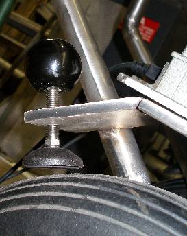 Het
mag de draaicirkel niet hinderen: het stuurwiel kan 180 graden draaien. Draad
getapt M12 voor remschroefdraad. Als rem gebruiken we verstelbare ronde rubberpoten
voorzien van een kogelgewricht. Voorboorgat: 10mm. Materiaal: Inox plat 100
x 8 x 80. Kogelkoppen gemonteerd voor de bediening van de remmen. Een en ander
is goed te zien op de foto. Het achterwielstel is nu helemaal afgewerkt en
meteen ook gladgeslepen met een fijnkorrelige lamellenschijf voor inox. Om
de remmen te verwijderen moeten nu wel eerst de wielen worden losgenomen.
Het
mag de draaicirkel niet hinderen: het stuurwiel kan 180 graden draaien. Draad
getapt M12 voor remschroefdraad. Als rem gebruiken we verstelbare ronde rubberpoten
voorzien van een kogelgewricht. Voorboorgat: 10mm. Materiaal: Inox plat 100
x 8 x 80. Kogelkoppen gemonteerd voor de bediening van de remmen. Een en ander
is goed te zien op de foto. Het achterwielstel is nu helemaal afgewerkt en
meteen ook gladgeslepen met een fijnkorrelige lamellenschijf voor inox. Om
de remmen te verwijderen moeten nu wel eerst de wielen worden losgenomen.
- 07.08.2006: lektest zonder pijpen op de bovenste windlade. Grote opruim
atelier. Poging om dit stofvrij te maken... het stof komt anders immers in
de windladen terecht en verstoort daar terdege de afdichtingen... Crash-tests
voor de PIC kode van K1-Q1 leveren tot hiertoe geen crashes op... tenzij om
13u30... crash op K1 en niet op Q1 dat nochtans dezelfde kode runt en bovendien
dezelfde input toegevoerd krijgt. Het wachten is nu op kode voor K2-Q6. Namiddag:
werksessie met Johannes Taelman. Back to assembly language: alle note/velo
boards nu geprogrammeerd in assembler i.p.v. C. Dit blijkt niet te crashen...
Noot 59.5 op het Q2 board blijkt een defekte mosfet te hebben. Lekken doen
zich nog voor op de noten 63.5, 65, 71, 73.5, 56, 60, 68.5, 80, 88, 96. Merkwaardig
is wel dat bij het verhogen van de winddruk tot 150 mm H20 de kleine lekken
eerder verdwijnen dan dat ze vergroten... Midi all notes off kommando nu meteen
ook geimplementeerd op alle noten-PIC's. (PIC software versie 1.0)
- 08.08.2006: Motor controller opnieuw geprogrammeerd: parameter 2 op 65Hz
ingesteld. De nu verkregen druktabel komt er uit te zien alsvolgt:
| midi value for ctrl. 7 |
motor frequency |
air pressure in mm H20 |
| 127 |
52.0Hz |
150mm |
| 117 |
50.4Hz |
145mm |
| 110 |
50Hz |
140mm |
| 95 |
48.6Hz |
135mm |
| 79 |
46.4.0Hz |
120mm |
| 70 |
44.5Hz |
110mm |
| 62 |
42.4Hz |
100mm |
| 56 |
40.5Hz |
90mm |
| 48 |
37.4Hz |
80mm |
| 43 |
35.1Hz |
70mm |
| 38 |
32.5Hz |
60mm |
| 33 |
29.5Hz |
50mm |
| 28 |
26.0Hz |
40mm |
| 24 |
23.0Hz |
30mm |
| 19 |
18.7Hz |
20mm |
| 13 |
12.9Hz |
10mm |
Tenzij Ghislain Potvlieghe grote bezwaren zou hebben, of problemen bij het
opsnijden van de pijpen, willen we graag het hele instrument stemmen en intoneren
op een winddruk van 120mm, dus bij een default midi waarde van 79. De marge
tot 150mm geeft ons dan nog steeds veel mogelijkheden om de pijpen te laten
overblazen in de duodeciem. Crash gekonstateerd in de PIC voor het midi hub
board... Oorzaak alsnog onbekend... Kan dit ook te maken hebben met de C-kode
die hiervoor werd ontwikkeld? We kunnen dat nagaan op een gelijkaardig board
ontwikkeld voor <Vitello> of <Krum>.
- 09.08.2006: Extra velo/hold board bestukt ter vervanging van het Q2 board
waarop noot 51 defekt was. Oorzaak? Wellicht een bij produktie kapotte diode
(BY228), zowat het enige onderdeel dat wanneer het kortgesloten is kan verklaren
hoe beide power mosfets de geest -met rookpluim- konden geven. De externe
bedradingen, inklusief de elektromagneet waren intakt. Na deze vervanging
werkt noot 59.5 terug normaal. Test en stem interface geschreven in GMT door
Kristof Lauwers. Toegevoegd aan de kode module qt.inc in de kompilatie m_robots.exe.
- 10.08.2006: Bestelling boordring en plat inox voor de konstruktie van de
spanhoepel voor de bovenste windlade. Inventarisatie van de nog lekkende kleppen
op de bovenste windlade. Remediering en afregeling van de klepzittingen. Het
boorgat voor noot 88 blijkt een kleine splinter te hebben. Dit repareerden
we met een precizie legring 12x24 spelingsvrij opgekleefd op het wawa hout
met cyaanacrylaat gel. Lekken-dichtings sessie nr.3. Rubberstrips binnengekomen
bij De Mulder..
- 11.08.2006: Bovenste windlade winddicht gemaakt met 10mm dikke cellulaire
rubberstrips, ook hier gekleefd op het wawa hout. Nieuwe test op lekkende
kleppen met winddruk 15mBar: kleine lekken nog gemeten op de pijpvoeten voor
55.5, 59.5, 60, 75.5, 77.5, 94. Met geplaatste pijpen zijn de lekken echter
onhoorbaar. Uitfreeswerk in het hout van de bovenste windlade voor de geleiding
van de 6mm inox spanschroeven. Ontwerp van de inox spanbeugel uit 3mm dik
inox bandstaal en een laskraag. Het aantal kleine lekken blijkt na een dag
spelen zelfs nog wat toe te nemen... nu ook lekken op 98, 98.5, 103.5, 105.5
- 12.08.2006: Nieuwe testsessie voor lekken: na wat inspelen op hoge druk
lekt nu eigenlijk alleen noot 65.5 nog konsiderabel. De andere lekken blijken
'vanzelf' te verdwijnen na enkele uren aktiviteit en luchtdruk. Experimenten
en metingen m.b.t. de mogelijkheden tot uitschakeling van de ventilator in
de Elipse 12V voeding. Deze maakt immers een volstrekt onwenselijk bijgeluid.
- 13.08.2006: Slijpen en vijlen van een afgeplatte kant volgens de afschuining
van de windlade aan de inox busmoeren (M6) waarmee deze wordt dichtgeklemd.
(8 stuks nodig, individueel vershillend).
- 14.08.2006: Qt gebruikt voor de produktie van Fernorchester klusters in
het M&M minimal koncert. Betrouwbaarheidstest.
- 15.08.2006: Duurzaamheidstesten elektronika. We testen 24 lang ononderbroken.
Haarlek op pijp 65.5 blijkt persistent. We zullen het polster moeten vervangen.
Ontwerptekeningen hef-handvat voor bovenste windlade.
- 16.08.2006: Uitwerking tekeningen voor afscherming windlade.
- 17.08.2006: Wachten op levering boordringen door Demar-Lux. Uitwerking test-software
voor Qt in GMT: modules die PIC per PIC afzonderlijk testen. Uitwerking user
interface voor kwarttoonsbesturing.
- 18.08.2006: Verdere ontwikkeling besturingssoftware.
- 19.08.2006: Software tests. Evaluatie van de noot-repetitie mogelijkheden
en snelheid.
- 20.08.2006: Verdere ontwikkeling Qt-specifieke software binnen de GMT omgeving.
- 21.08.2006: Levering boordringen door Demar-Lux. Precizie uitzaag- en vijlwerk
voor de onderdelen van de sluitingsbeugel voor de bovenste windlade. Uiteindelijk
beslisten we -ondanks estetische bezwaren- toch maar 30x30x3 inox hoekprofiel
te gebruiken voor het recht gedeelte van de windlade. Wanneer later een aanraakbeveiliging
nodig zou blijken, kan deze makkelijk hieraan worden bevestigd.
- 22.08.2006: Konstruktie afdichtings klembeugel voor bovenste windlade: TIG
laswerk. Gladschuren inox walshuid en lasnaden. Boren van de gaten voor de
M6 x 100 bouten waarmee de windlade dichtgeklemd wordt. Uiteinden van de M6
bouten voorzien van pootsokken in zwart PVC.
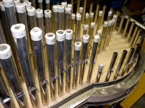
- 23.08.2006: Naadloze inox buis met binnenmaat 6 mm besteld voor de konstruktie
van de afstandsbussen voor de bevestigingsbouten van de windladen. Diverse
ontwerpen voor pijpbevestiging getekend.
- 24.08.2006: Klasseren en ordenen van de plannen en ontwerpnotities op papier.
De stapel papier was al aangegroeid tot ca. 600 bladzijden...
- 25.08.2006: Nog steeds geen levering van de melexis sensoren in zicht. Kabelbundels
aangelegd en draden op lengte getrimd.
- 26.08.2006: Reverse engineering van de Ellipse/ Sunpower 12V power supply,
met het oog op de uitschakeling van de ventilator. Blokkeren van de schoepen
helpt ons niet, want dan start de voeding niet op...
- 27-31.08.2006: ontwerp en bouw prototypes voor alternatieve voedingen 25A
met regelbare uitgangsspanning.
- 01-03.09.2006: Voorbereiding voor het transport van <Qt> naar het
atelier van Ghislain Potvlieghe voor het stemmen en intoneren.
- 04.09.2006: Levering Melexis sensoren via Koning en Hartman. Meteen proefprintjes
gesoldeerd voor evaluatie van de gevoeligheid en de karakteristieken. Lateraal
gemagnetiseerde ronde staafmagneten (diameter 12mm) demonteerden we uit eenvoudige
DC motoren met permanent magnetische tweepolige ankers. Deze kunnen op de
assen van de kleppen worden gemonteerd.
- 05.09.2006: pogingen om gaten te draaien in de ferriet magneten op de draaibank
blijken niet suksesvol: het ferriet splintert en verbrokkelt. Wellicht moeten
zulke gaten geslepen worden, maar daarvoor is het toerental van onze metaaldraaibank
veel te laag. Ook moet een zeer goede koeling voorzien worden want de magneet
verliest zijn eigenschappen wanneer die te warm zou worden (Bij het bereiken
van het Curie punt gaan de magnetische eigenschappen irreversibel verloren).
Opzoekingswerk naar specs van het magneetmateriaal: anisotropisch gesinterd
ferroxdure, Philips kataloognummer 4203 014 80120 (Components and materials
handbook, Piezoelectric Ceramics , Permanent Magnet materials, part 16, january
1982).. Het materiaal is Ferroxdure 330, een Strontium-ferriet legering SrFe12O19.
Een recenter vervangtype vonden we in de katalogus van 1991, onder het bestelnummer
4203 014 80290, eveneens met diametrale magnetisatie.
- 06.09.2006: Proefopstelling voor positionering DSP-sensoren van Melexis.
Er treden problemen op met trillingen die op het signaal van de sensoren gesuperponeerd
voorkomen. Voor een deel zijn die toe te schrijven aan de stapjes veroorzaakt
door de stappenmotoren.
- 07.09.2006: Proefopstelling met elastische montage van de sensoren. Dit
werkt als een mechanisch low-pass filter.
- 08.09.2006: Proefkonstruktie voor bevestiging diametraal gemagnetiseerde
cilinders op de assen van het klepmechanisme. Spinax askoppelingen (met een
elastische insert) blijken het meest geschikt, want daarmee kunnen de magneten
eenvoudig en precies worden gepositioneerd en bijgesteld. Pech: bij het tappen
van M4 slotgaten in de kogellagerhouders van de kleppen is in een van de blinde
gaten het tapijzer afgebroken... Om het vastzittend tapeind te verwijderen
hebben we een linkse boor nodig...
- 09.09.2006: Verwijdering afgebroken tap met konisch wringijzer met linkse
spiraal, ingekocht bij MEA (Kukko). Herstelling M4 schroefdraad. Plaatsing
afstandsbussen voor de sensordrager. Bij de konstruktie van de tweede sensorhouder
voor de onderste windlade brak evenwel opnieuw de tap af in het blind gat..
Deze keer werkten we 6uur alleen om het tapuiteinde te verwijderen. Uiteindelijk
lukte het alleen na invriezen op -40 graden..De sensor-chip, hier gemonteerd
met twee M2 boutjes in inox op een stukje aanpasprint voor SMD-SOIC behuizing
naar DIL en dan nog op een stuk glasvezel-epoxy plaat als mechanische drager,
voorzien van twee M4 inox inbus boutjes, ziet er uit als:
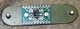 De Melexis chip zelf heeft slechts 8 pootjes, zodat het merendeel der soldeereilandjes
voor de SOIC niet is gebruikt. De spinax askoppeling (met rode elastische
insert) , voorzien van de diametraal gemagnetiseerde magneet als:
De Melexis chip zelf heeft slechts 8 pootjes, zodat het merendeel der soldeereilandjes
voor de SOIC niet is gebruikt. De spinax askoppeling (met rode elastische
insert) , voorzien van de diametraal gemagnetiseerde magneet als: 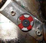 De magneet kan vrij worden gepositioneerd (pool plaatsing tegenover de sensorchip)
in de rode insert. Geassembleerd op de M4 hexagonale MF 40mm afstandsbussen
en de as ziet het eruit als:
De magneet kan vrij worden gepositioneerd (pool plaatsing tegenover de sensorchip)
in de rode insert. Geassembleerd op de M4 hexagonale MF 40mm afstandsbussen
en de as ziet het eruit als: 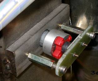
- 10.09.2006: Bedrading sensoren naar het midihub board (4polige Weidmuller)
met afgeschermde kabel. De afregeling van de sensorpositie kan pas gebeuren
in koordinatie met de betreffende PIC software.
- 11.09.2006: Solderen SMD 100nF caps (3) tussen de pootjes van de melexis
SOIC MLX90316 op beide opzetprintjes. NC pinnen aan massa gelegd. Dit werkje
moest onder de mikroskoop gebeuren... Printjes voorzien van een 3-polige SIL
header.
- 12.09.2006: Voorzieningen solderen en berekenen voor signaal-konditionering
op het midi-hub board voor de ontvangst door de PIC van de signalen afkomstig
van de melexis sensoren.
- 13-17.09.2006: Ontwerp software modellen voor de klepregelingen. Studie
van het door de inertie van de klep veroorzaakt overshoot probleem en de oscillaties
die dat met zich kan brengen.
- 17.09.2006: Definitief vastsolderen onderdelen voor het analoge frontend
gedeelte voor de ontvangst van de melexis sensor signalen op het midihub board:
op elk van beide ingangskanalen 10k parallel met 4n7 naar massa. (Weidmueller
pinnen 5 en 6). Test met aangesloten hub board kan echter niet gebeuren omdat
de PIC ingangspinnen nog als uitgang en logisch 0 zijn geprogrammeerd.
- 18-19.09.2006: Start revizie van de PIC kode op het midihub board.
- 20-26.09.2006: Aanpassen besturingssoftware in GMT. Voor een vlotte integratie
binnen deze programmeeromgeving kunnen we best Qt implementeren als twee gekoppelde
musici, elk opererend op een eigen midi kanaal.
- 27-28.09.2006: Strukturen ontworpen in GMT voor de weergave van kwarttoons
harmonie-strings op <Qt>. De uitbreiding van de fuzzy-logic sets voor
de berekening van akkoordstrukturen is nu aan de orde.
- 29.09.2006: Start aanleggen kabelbomen en bundels met nylon ligaturen en
Spirawrap. Eerste verplaatsing van <Qt> buiten het atelier.
- 30.09.2006: Testkode voor shepard akkoorden en tonen geschreven en getest
op de (voorlopig nog) ongestemde Qt.
- 01.10.2006: Redaktie funkties en procedures voor de berekening van de dissonantie
van veelklanken met vrije opbouw in kwarttoonskontekst op grond van de bevindingen
uit de psychoakoestiek.
- 02.10.2006: Werkplan opgesteld voor het stemmen en intoneren. Foto van Qt
in dit stadium van afwerking:
- 03.10.2006: Verder kode ontwikkelingswerk aan de kwarttoonsharmonie biblioteek
in GMT ten behoeve van goed gevormde komponisten.
- 04.10.2006: Voor de 12V houd-spanning voor de elektromagneten gebruiken
we uiteindelijk een SPS600P-12 (12V/50A, 600W), Sunpower - Dehner Elektronik
Gmbh of Ellipse. Hier zijn echter wel enkele ingrepen nodig om de geluidsproduktie
door de ingebouwde 'made in Taiwan' ventilator het zwijgen op te leggen We
kunnen voor deze ingreep terugvallen op onze bevindingen bij de ontwikkeling
van <pp2>, onze player piano waarin een voeding van hetzelfde type werd
gebruikt. We citeren uit het bouwverslag dat we daarover opstelden: 'The fan
is connected internally to the main PC board with a small 3-pin receptacle.
The black wire connects to the negative power output, the red one feeds the
12V rated (140mA) fan motor and the yellow one seems to be some kind of sensor.
On the 12V/50A model, if you mechanically block the fan or unplug the connector,
the power suppy shuts down. It needs to see a voltage no smaller then 50mV
on the yellow connection. So we replaced the fan with a resistor of 100 Ohms
/ 2Watt in series with 0.47 Ohm.' Deze ingreep voerden we dan ook eveneens
uit in deze voeding. De uitgangsspanning werd bij gelegenheid van deze ombouw
meteen verlaagd tot 10.8V, 10% onder de nominale uitgangsspanning, de low
limit volgens de specifikaties van de fabrikant. De maximale stroom blijft
behouden op 50A. De oorspronkelijke ventilator werd helemaal verwijderd. Het
ontstane gat blijft open voor de ventilatie.
- 05.10.2006: Definitief honen van de gaten voor de plaatsing van de hoge
pijpen. Levering van de naadloze inox buis met binnenmaat 6mm voor de konstruktie
van de afstandsbussen voor de bevestigingsbouten van de windladen.
- 06.10.2006: Afslijpen lasnaden en grof slijpwerk zichtbare delen in inox.
- 07.10.2006: Ontwerp polykarbonaat bescherming van de midi-ingangsschakeling,
dit met het oog op gebruik door (domme) studenten.
- 08-09.10.2006: Simulatie in software gemaakt voor de opsnede van de pijpen
bij een winddruk van 12 mBar.
- 09-15.10.2006: Verdere ontwikkeling met Johannes Taelman van de kode voor
de PIC processor op het midihub board m.b.t. de aansturing van de stappenmotoren
voor de kleppen. Voor het overige is het wachten op Dierik en Ghislain Potvlieghe
voor het intoneren... Overigens verliezen we vanaf nu erg veel tijd door dagen
waarop we les moeten geven en die dus voor research en development verloren
zijn.
- 19.10.2006: research DS-PIC kodering voor een kwarttoonsgenerator ten behoeve
van het precies stemmen van de pijpen. Korrektie PCB ontwerp voor de velo/hold
boards. (cfr. bug 28.07.06) Diezelfde fout is nu ook ontdekt in de PC boards
voor de pulse-only automaten met 28 uitgangen waarin van dezelfde PIC gebruik
wordt gemaakt.
- 20.10.2006: Van het nieuwe gekorrigeerde board bestelden we meteen 25 exemplaren,
verguld.
- 22-23.10.2006: Bestukken en solderen van de nieuwe pas geleverde PC boards:
K1, Q1, K2, Q2.
- 24.10.2006: Bestukken en solderen boards voor K3, Q3.
- 26.10.2006: Bestukken en solderen boards voor K4, Q4.
- 27.10.2006: Bestukken en solderen boards voor K5, Q5.
- 28.10.2006: Bestukken en solderen boards voor K6, Q6.
- 29-31.10.2006: Ontwerp midi bestuurbare tuning synth met 1 cent resolutie,
gebruik makend van een DS pic. Proefprint voor evaluatie opgebouwd.
- 01.11.2006: ontwikkeling evaluatie software in GMT voor het DS-PIC board.
- 07.11.2006: Herstelling mosfets op het originele board Q2.
- 08-10.11.2006: Redaktie besturingskode voor het spelen van diverse kwarttoonstoonladders.
- 12.11.2006: Experimenten met het gebruik van de basnoten van de in opbouw
zijnde kromatische automaat <Bako> voor de extensie in de bas. De vraag
hierbij is of het eigenlijk wel zinvol is de tessituur in kwarttonen uit te
breiden naar de bassen toe. Voor <Qt> zelf hebben we dergelijke uitbreiding
van in den beginne zelfs nooit ernstig overwogen, vanwege de enorme afmetingen
die het instrument dan zou verkrijgen. Met doorslaande tongen is het best
haalbaar maar blijft het sterk de vraag of onze toonhoogteperceptie toereikend
is voor een zinvol gebruik van kwarttonen in dit tessituurbereik.
- 13-16.11.2006: Tests onder programma besturing: implementatie in kompositiesoftware
voor GMT
- 17.11.2006: Levering MEA inox bouten.
- 21.11.2006: Overleg met Dierik en Ghislain Potvlieghe i.v.m. stemmen en
intoneren.
- 23.11.2006: Slijpwerk lasnaden in het inox chassis.
- 25.11.2006: Narekenen druk op de ventielen: bij 10mB druk is de kracht uitgeoefend
op de wanden van de windlade 1kN/m2. Om de grootste ventielen, met een oppervlakte
van ca.500mm2 te openen moet dus een kracht overwonnen worden van 0.5N. Voor
de kleinste ventielen is die kracht uiteraard veel geringer.
- 28.11.2006: Nog maar eens gepoogd een werkafspraak te maken met Dierik Potvlieghe
voor het stemmen en intoneren...
- 29.11.2006: Research naar toepassingsmogelijkhden van Freescale Electronics
monolitische druksensoren in de windlades. We beschikken over samples van
de types MPXV7002DP (bipolair met een drukbereik van -200kPa tot +200kPa),
MPX10GP en M2500GM.
- 30.11.2006: Werkvergadering met Peter Quintelier i.v.m. afstudeerprojekt
Hogent, dept. industriele wetenschappen, rond de mogelijkheden om orgelpijpen
te vervaardigen uit kunststoffen. Dit kan potentieel de kostprijs van later
te bouwen orgelachtige automaten en instrumenten in hoge mate reduceren zonder
dat aan kwaliteit moet worden ingeboet. Bovendien kan het duurzaam en miljeuvriendelijk
zijn, aangezien lood uit het produktieproces, overeenkomstig mundiale richtlijnen
(RoHS) terzake, moet worden geweerd.
- 01-11.12.2006: Verder werk aan de kwarttoons-harmonie software.
- 05.12.2006: uitleg Thomas Smetryns i.v.m zijn kompositieopdracht voor <Qt>.
- 06.12.2006: Opbouw nieuw midihub board (verguld) met verbeterde layout voor
de afhandeling van de sensor signalen.
- 07.12.2006: Evaluatie en test print opgebouwd met Freescale druksensor type
MPXV7002DP.
- 08.12.2006: De schakeling werkt goed, maar het ware beter een unipolaire
sensor toe te passen in Qt. De bipolaire proefschakeling kan goed worden ingezet
voor <Bako> en komt natuurlijk ook in aanmerking van <Ake>, wanneer
die aan een upgrade toe is.
- 09.12.2006: Afdichting lichtgaten en buitenzijde doorvoer van de kabelboom
in de onderste windlade.
- 11.12.2006: Overlegvergadering met Jan Rispens over kompositieopdrachten
voor muziek voor <Qt>.
- 12.12.2006: Eerste stem- en intoneersessie met Dierik Potvlieghe. Alle C's
juist gestemd en geintoneerd bij 15mB winddruk (motor frekwentie 52Hz). Pijpwerk
meegegeven met Dierik voor afwerking. Diapason 440Hz. Reeds opgesneden en
geintoneerd zijn de noten 36,37,48,49,60,72,84,96,97,98,99,105,108.
- 13-14.12.2006: Stemmen en intoneren van het pijpwerk: insnijden van de labia
en vastsolderen van de pijpdeksels. Deze werken worden uitgevoerd in het atelier
van Ghislain Potvlieghe.
- 15.12.2006: Tweede overlegvergadering met Jan Rispens i.v.m. te schrijven
muziek voor <Qt>.
- 20.12.2006: Overleg met Hans Roels ivm. kompositie voor <Qt>
- 21.12.2006: Overleg met Kris De Baerdemacker ivm kompositie voor solo <Qt>.
- 25.12.2006: Aanleggen van de kabelbomen. (Spirawrap)
- 26.12.2006: Tweede voorontwerp pijphouder voor onderste windlade.
- 16-31.12.2006: Stemmen en intoneren pijpwerk, hoge windlade.
- 30.12.2006: Ontwikkeling klepbesturingsprogramma in de nieuwe C compiler
voor MPLab (Microchip).
- 31.12.2006: Poolshoogte genomen mbt de stand der werken bij Dierik Potvlieghe...
- 01.01.2007-03.01.2007: Onderzoek plaatsingmogelijkheden voor Freescale druksensoren.
- 04-10.01.2007: experimentele opstelling gemaakt met een oude akkordeonbalg
voor de bepaling van de dynamische eigenschappen van een regelkring bestuurd
door een mikrokontroller.
- 14.01.2007: Nieuws van Dierik Potvlieghe, op de hoogste twee oktaven na,
zijn de pijpjes gestemd en geintoneerd... Nog even geduld.
- 16-18.01.2007: ontwikkeling van kode biblioteek voor de konversie van akoestische
spektra naar kwarttoons-harmonie strings. Verdere ontwikkeling kwarttoonsharmonie
funkties, inklusief spektraal funkties en procedures. Voor source kode en
gekompileerde dll's : g_har.bas en g_har.dll.
De funktiedeklaraties voor alle geexporteerde funkties staan in g_har.bi
- 19-21.01.2007: test, evaluatie en debugging van de kwarttoonsbiblioteek
in gmt. Reorganisatie van g_mus en g_har.
- 22.01.2007: Akkoordnummer funkties ondergebracht in de gmt file g_crd.inc.
Deze wordt gekompileerd samen met g_har tot g_har.dll. Alle exports staan
in g_har.bi. De funkties kunnen ook in C worden gebruikt.
- 22-26.01.2007: Verdere konsistentie tests op de GMT kwarttoons biblioteek.
- 27.01.2007: Werkdag pijpwerk met Dierik Potvlieghe. Stemmen en intoneren
oktaaf 48-59.5. Opsnede en intonatie afgewerkt.
- 28.01.2007: Op maat brengen en voorlopig dichtkleven van de onderste pijpen
(36-47.5). Dit ging nog best met de Ridgid cirkelzaag voor staal. Besturingskode
voor Qt verder van bugs ontdaan. Utility toegevoegd om 'gewone' toonladders
te spelen ter kontrole van de stemming op het gehoor.
- 29.01.2007: Bespreking met studenten: kompositie voor kwarttoonsinstrumenten.
Yvan Vander Sanden is er al goed mee opgeschoten.
- 31.01.2007: Stem en intoneersessie met Dierik Potvlieghe: pijpen 36-47 en
36.5 tot 39.5 opgesneden, geintoneerd en gestemd.
- 01-02.2007: Verdere ontwikkeling kwarttoonskode.
- 03.02.2007: Stem en intoneersessie met Dierik Potvlieghe. Pijpen 36-60.5
geintoneerd en gestemd. Pijpen 61- 78 geintoneerd en opsnede gekorrigieerd.
Konstruktie inox beugels voor de laagste 24 pijpen: 10 beugels dichtgelast
en op maat gebracht.
- 04.02.2007: Verder werk konstruktie beugels. Grote nood aan geschikte gekalibreerde
plooimallen...
- 06.02.2007: Stem en intoneersessie met Dierik Potvlieghe.
- 07.02.2007: Opmetingen mensuren en verder stemwerk met Dierik Potvlieghe.
Mensuurtabellen aangepast. Pijpen onderste
windlade terug naar atelier Potvlieghe voor dichtsolderen pijpdeksels.
- 08.02.2007: Vergadering met Jan Rispens i.v.m. kwarttoonsmuziek voor Qt.
- 09.02.2007: Opmeting gestemd pijpwerk noten 48-72.
- 12.02.2007: soldeerwerk pijpdeksels 36-47.5. Uittekenen konstruktie beugels
voor onderste pijpen.
- 15.02.2007: verder werk aan pijphouder en beugel.
- 17.02.2007: werkdag stemmen en intoneren met Dierik Potvlieghe. Laagste
windlade is nu gestemd en dichtgesoldeerd. Daar vallen alleen nog wat onregelmatigheden
in de geluidsterkte op te lossen. Eventueel kunnen we harmonische bruggen
plaatsen boven de kernspleten. De gehele bovenste windlade is nu ook gestemd
en geintoneerd. <Qt> speelde voor het eerst korrekt Charles Ives kwarttoonsmuziek.
Bij wijze van intonatie test probeerden we natuurlijk ook Bachs bekende toccata
en fuga in re klein uit...
- 18.02.2007: Klep 43 blijkt soms te haperen. Nazicht mechanika. De integrale
Goldberg Variationen zijn nu beschikbaar voor Qt. De toonhoogte blijft aanvaardbaar
stabiel bij variatie van winddruk in het gebied tussen 10 en 15 mBar.
- 19.02.2007: Qt test versies voor Charles Ives' "Three Quartertone Pieces",
Wiesniegradky enz... klaar gemaakt.
- 20.02.2007: Eerste publieke try out met Qt: Toccata en Fuga in re klein
van Bach gespeeld. Opname gemaakt van Charles Ives.
- 21.02.2007: Qt demo gegeven voor Ghislain Potvlieghe die de nog te solderen
pijpen terug meeheeft naar het soldeeratelier.
- 22.02-09.03.2007: Soldeerwerk pijpdeksels.
- 10.03.2007: Herplaatsing pijpen en fijnstemming. Volledige werkdag stem
en intoneerwerk. Nog 12 pijpen blijven te solderen (hun korpus werd immers
weer wat uitgelengd...).
- 11.03.2007: Soldeerwerk in het atelier van Ghislain Potvlieghe.
- 12.03.2007: Plaatsing van de ontbrekende 12 pijpen en fijnstemming daarvan
door Ghislain Potvlieghe. Test met muziek van Yvan Wiesnegradsky en Charles
Ives.

- 13.03.2007: Repetitie en file-redaktie met Thomas Smetryns van diens kwarttoonsstuk
met Qt. Demonstratie Qt voor Johannes Taelman. Bespreking van de verder nodige
PIC kode voor de windkleppen.
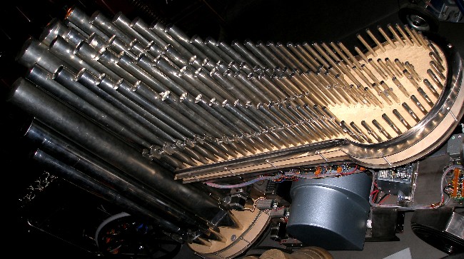
- 14.03.2007: Repetitie en evaluatiesessie.
Op de fotoos: het integrale pijpwerk, volledig afgewerkt en met dichtgesoldeerde
dekseltjes.
- 15-18.03.2007: Proefopnames kwarttoonsmuziek Wiesnegradky, Haba, Ives, Smetryns.
- 19.03.2007: Orkestratie werk met Qt door Sebastian Bradt.
- 20.03.2007: Afspraak Frank Nuyts voor demo met Qt.
- 21.03.2007: Frank Nuyts hier voor demo en bespreking mogelijkheden van Qt.
- 22-26.03.2007: redaktie van de hoofdstukken over stemming en temperament,
ter onderbouwing van de validiteit van de kwarttoons <Qt> in gelijkzwevende
stemming in mijn kursus akoestiek.
- 27.03.2007: Lezing voor Orpheus instituut over mikrotonale stemmingen. Voorstelling
van het Qt projekt.
- 28.03.2007: Basistekst rond stemming
en temperament beschikbaar gesteld op internet. Een gebruiker heeft vernielende
velocity waarden losgelaten op qt, met als gevolg een heleboek lekken en niet
terugkerende kleppen.... Nu zijn er weer lekproblemen met de noten 60, 67,
68, 84,94, 103.5. Op de lage windlade is er een probleem met noot 43 waarvoor
het ventiel niet steeds voldoende ver geheven blijkt te worden. Noot 37 heeft
klaarblijkelijk een ander velo bereik en heeft wat hogere waarden nodig.(nagaan:
is daar een ander type veer geplaatst?)
- 02.04.2007: Alle noten-pics opnieuw geprogrammeerd met velocity scaling
zowat een faktor tien kleiner dan voorheen. Sysex geimplementeerd voor alle
velocities.
- 03.04.2007: Toch nog steeds problemen met lekken op 67-68...
- 04.04.2007: Hans Roels research op mogelijkheden van Qt. Lekken op 67-68
blijven persistent.
- 07.04.2007: Frank Nuyts stuk klaar voor de eerste tests op Qt: "Two
quartertone pieces don't make a half one"
- 10.04.2007: Lek op noot 70.
- 13.04.2007: Heropmeting veertjes op de pallet elektromagneten. Huidige afmetingen
zijn 0.4 x 3.4 x 26 (draaddikte, veerdiameter, lengte) met een spoed van 1.44mm
(18 windingen) zoals geleverd door Laukhuff. Beter zou zijn 0.5 x 5.0 x 25
of 0.5 x.4.5 x 25, met een spoed van 1.5mm. Die zijn evenwel nergens leverbaar
en dus laten we ze aanmaken bij Industrieveren Noel Algoet nv. Met de nieuwe
veertjes moeten we minder problemen hebben met lekken enerzijds en anderzijds
ook een betere aanslag-regelbaarheid kunnen verkrijgen. Uiteraard zal dit
de velocity scaling en de aanslaggevoeligheid wijzigen zodat we de look-ups
in de firmware zullen moeten herberekenen en aanpassen.
- 14.04.2007: Voorlopige herberekening hold-voeding in funktie van de nieuwe
veren.
- 18.04.2007: Kwarttoonsstemming gedemonstreerd voor akoestiek studenten,
met luistervoorbeelden.
- 20.04.2007: Nu Piperola en 7 andere automaten op reis zijn naar Vilnius,
kunnen we experimenteren met de opstelling van Qt binnen het orkest.
- 21.04.2007: Tests op velo-sturing.
- 03.05.2007: Nieuwe veertjes nog niet geleverd...
- 04.05.2007: de veertjes worden pas volgende week geleverd...
- 07.05.2007: Levering twee sets van 500 veertjes:0.5 x 5.0 x 25 of 0.5 x.4.5
x 25, spoed 1.5mm. Opmetingen ventiel-karakteristieken met de drie verschillende
veertjes. De resultaten zijn de zijn in deze grafiekjes:
 Het
is duidelijk dat met de originele Laukhuff veertjes (onderste grafiek) niet
veel mogelijk kan zijn op gebied van kontrole van de opening der ventielen
ten behoeve van expressiemogelijkheden. Bovendien is de afsluitkracht van
de ventielen met deze veertjes te klein voor de hier toegepaste winddruk,
wat tot lekken aanleiding kan geven. De sterkste veren (bovenste grafiek)
sluiten de ventielen perfekt af, maar openen net iets te langzaam waardoor
snelle staccatos in het gedrang zouden kunnen komen. De veertjes uit de middelste
grafiek laten duidelijk het breedste regelbereik toe. De PWM sturing voor
note-key pressure moet voor deze veertjes een regelbereik hebben van 20% tot
100%.
Het
is duidelijk dat met de originele Laukhuff veertjes (onderste grafiek) niet
veel mogelijk kan zijn op gebied van kontrole van de opening der ventielen
ten behoeve van expressiemogelijkheden. Bovendien is de afsluitkracht van
de ventielen met deze veertjes te klein voor de hier toegepaste winddruk,
wat tot lekken aanleiding kan geven. De sterkste veren (bovenste grafiek)
sluiten de ventielen perfekt af, maar openen net iets te langzaam waardoor
snelle staccatos in het gedrang zouden kunnen komen. De veertjes uit de middelste
grafiek laten duidelijk het breedste regelbereik toe. De PWM sturing voor
note-key pressure moet voor deze veertjes een regelbereik hebben van 20% tot
100%.
- 12.05.2007: Pijpwerk bovenste windlade verwijderd en windlade zelf helemaal
losgenomen (4u werk) met het oog op afregeling en vervanging van alle ventielveertjes.
Plaatsing nieuwe veertjes. Lektest in open positie met licht. Remontage windlade
en pijpwerk... Wat blijkt: nieuwe lekken op 58, 93 en 105. Het lek op 105
ging vanzelf dicht na enige tijd. Noot 93 heeft klaarblijkelijk een lekkend
polster. Bij 58 is iets anders aan de hand. Immers vanzodra we de pijp zelf
wegnemen, sluit het ventiel perfekt af....
- 13.05.2007: Pijpwerk opnieuw weggenomen op hoge windlade en opnieuw begonnen:
ventiel 58 bleek geen veertje te hebben, wat uiteraard het niet funktioneren
verklaart... Lekjes op 105 en 93 gekorrigeerd. Na assemblage en opnieuw plaatsen
van het pijpwerk blijkt alles nu perfekt en lekvrij te werken! Nog te doen:
vervanging veertjes op de onderste windlade.
- 14.05.2007: GMT testkode geschreven voor de exakte bepaling van de repetitie-rate
met de nieuwe veertjes. (Module m_robots.exe, selektie Qt). Test procedure
geschreven voor bepaling van de toelaatbare modulatiesnelheid en diepte voor
de regeling van de winddruk via de motorkontroller.
- 15.05.2007: Test <Qt> in M&M koncert rond het tema paaldans.
- 16.05.2007: Kompositie demo stukje voor <Qt>: 'Wouwel; (eerste werktitel).
- 18.05.2007: Experimenteer sessie Hans Roels met Qt.
- 20.05.2007: 'Wouwel'
afgewerkt.
- 21.05.2007: 'Wouwel' opgenomen en als MP3 op de site beschikbaar gesteld:
Recording
- 25.05.2007: Test stukjes studenten op Qt.
- 29.05.2007: Experimenten met ruimte opstelling van Qt.
- 01.06.2007: Studentenstukjes klaargemaakt voor <Qt>
- 02.06.2007: Stukken Wouter Simoens, Michiel De Malsche, Evert Bogaert en
Simon De Poorter afgespeeld en beluisterd.
- 04.06.2007: Vertrek naar New York voor de NIME konferentie waar we <Qt>
voorstellen.
- 12.06.2007: Qt partijen voorzien in de orkestraties van de tangos voor het
tango koncert van 14.06. Onderzoek van Qt mogelijkheden door Hans Roels.
- 13.06.2007: Finalisatie tango orkestraties met Qt.
- 14.06.2007: Tango koncert met Qt.
- 15.06.2007: Proefopnames van enkele tangos met Qt gemaakt.
- 03.07.2007: Demos voor konservatoriumstudenten onderzoeksmetodiek.
- 04.07.2007: Glissando tests.
- 05.07-30.07.2007: Experimenteer en kompositie werk met komponisten die een
opdrachtwerk schrijven voor Qt: Kristof Lauwers, Sebastian Bradt, Hans Roels.
- 01.08.2007: Repetitie met Marcel Ketels en Dirk Moelants in oude muziek
repertoire met Qt.
- 07.08.2007: Alle werk aan Qt valt stil wegens chirurgische ingreep op mijn
linkerwijsvinger. Duur van de arbeidspauze vermoedelijk ca. twee weken...
- 12.08.2007: lek op pijp 79 (polster) gekorrigeerd.
- 13.08.2007: Test kompositie Qt Barbara Buchowiec (Dwergenmars). Repetitie
in oude muziek met Qt.
- 14.08.2007: Lek op 79 veroorzaakt door repetitie-resonantie met overdreven
velo's in stuk Sebastian Bradt (Taxidermie) . Daardoor is het polster intern
verbogen geraakt...
- 19.08.2007: Speciaal werktuig gemaakt om het polster van noot 79 bij te
buigen zonder de windlade te moeten openen... De operatie lijkt voorlopig
in elk geval gelukt. Ook mijn linkerwijsvinger lijkt het weer te doen...
- 20.08.2007: Tests <Qt> onder PD besturing via een external DLL geschreven
door Yvan Vander Sanden voor diens eindexamen kompositie volgende week.
- 21.08.2007: De tremulant zoals we hem bouwden voor <Qt> is eigenlijk
een debiet-tremulant. Wanneer slechts weinig pijpen aktief zijn is het windverbruik
dermate laag, dat het effekt van de tremulant minimaal is. Pas bij heel brede
samenklanken en een overeenkomstig hoog luchtverbruik, is de tremulant effektief.
De praktische ervaring wijst echter uit, dat ten gronde, de funkties van de
tremulant eigenlijk ook overbodig kunnen worden gemaakt: immers, gezien de
mogelijkheid om de velocity van elke klep afzonderlijk te sturen, is het mits
een geschikte kommandoset perfekt mogelijk elke pijp van een individuele tremulant
te voorzien. Daartoe dient de gewenste noot met een relatief hoge velocity
gespeeld te worden, gevolgd door een periodieke reeks aan/uit kommandos voor
dezelfde noot maar nu met minimale velocity. Het tempo van de periodiciteit
kan vrij worden gekozen (maximaal ca. 20Hz), de aan-uit verhouding eveneens.
Periodieke modulatie van de aftertouch is natuurlijk ook mogelijk. Aan de
implementatie daarvan op mikrokontroller nivo moet nog verder gewerkt worden.
Enkele praktisch uitgevoerde experimenten wezen trouwens uit, dat de bouw
van een druk-tremulant eigenlijk vrij eenvoudig kan gerealiseerd worden door
simpelweg een bas-luidspreker met een grote konus-verplaatsing in de windlade
in te bouwen. Door deze luidspreker aan te sturen met een sinusvormig signaal
van 0.1 tot 20Hz krijgen we een tremulant, gebaseerd op de volumeverandering
van de windlade.
- 23.08.2007: Studie van het transportprobleem van <Qt>. De zo goed
als professioneel onbruikbare mierezaal in de Hoogpoort met haar ontoegankelijk
podium (geen goederenlift, te kleine toegangsdeuren, steile trappen...) speelt
ons parten en bezorgt ons zware hoofdbrekens. Het gewicht van Qt hebben we
nagemeten: 210kg (meetfout 10%). Met vier sterke mannen en singels is Qt wel
te heffen, maar wanneer trappen in het spel zijn is de gewichtsverdeling erg
ongelijk, waardoor bijna het hele gewicht door twee man moet kunnen worden
gedragen. Konstruktie van een draagstang voor het manueel heffen van de achterzijde
van het orgel evenals van een draagberrie struktuur aangrijpend op de vooras.
Dit maakten we uit gewoon staal (ST42) , en dus niet uit inox, enerzijds uit
kostprijsoverwegingen en anderzijds omdat deze onderdelen slechts hulpstukken
zijn voor noodtransport in ontoegankelijke ruimtes. Bij vlakke horizontale
opstelling is het gewicht op de beide achterwielen samen 67kg, terwijl dat
op de voorste wielen samen 143kg beloopt. Het gewicht op de voorste wielen
is niet gelijk verdeeld, wat komt door de plaatsing van de motor. Het rechterwiel
vooraan draagt 55kg, terwijl het linkerwiel 88kg draagt. De konstruktieschets
ziet er in horizontale projektie uit als: (draagstruktuurstukken gekeurd in
rood en blauw)

- 24.07.2007: Transporteerbaarheidstest. Verhuisfirma Vervaet gekontakteerd
door het transport naar de Hoogpoort, waar <Qt> wordt gebruikt voor
het kompositie-examen van Yvan Vander Sanden. Vervaet wil het uiteindelijk
niet doen... Zoektocht naar een ander bedrijf. Konstruktie voorlopige transport-pijphouder
voor de onderste windlade in 50mm dik ge-expandeerd polyurethaan. Aan het
uitmeten en uitsnijden van de vierentwintig gaten hebben we niet minder dan
negen uur gewerkt! Met deze pijphouder moet het mogelijk zijn <Qt> met
een lier of katrol op een helling van niet meer dan 15 graden omhoog te trekken.
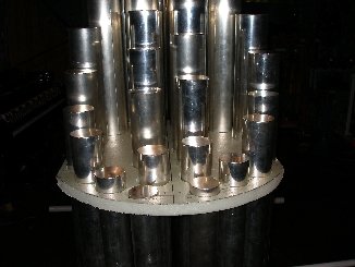
- 25.07.2007: Bouten M20 op draagberrie-struktuur vastgelast. Alleen de 10mm
dikke stalen basisplaat blijft los. De moeren moeten onderaan met een 30mm
ringsteeksleutel en een borgring worden vastgezet. Draagberrie gespoten in
wit RAL9010. De spanklemmen voor de achterkant waardoorheen de 5/4" draagbuis
komt eveneens wit gespoten.
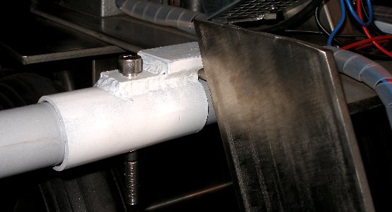
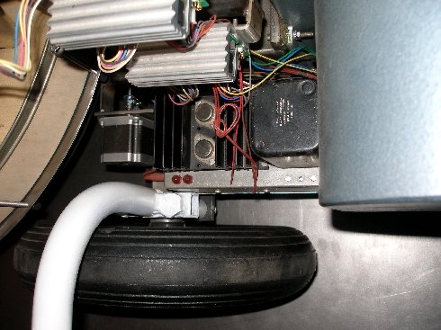
- 26.07.2007: Start precizielaswerk voor de konstruktie van een meer definitieve
inox pijphouder voor de voorste reeks pijpen. Konstruktiehoepel uit inox plat
30x3, diameter 68.5mm. Diagonaal-stuk (links q-pijpen, rechts k-pijpen) ingelast.
 Nog geen nieuws van de transportfirma met betrekking tot de verhuis van Qt
naar de zaal van het konservatorium.
Nog geen nieuws van de transportfirma met betrekking tot de verhuis van Qt
naar de zaal van het konservatorium.
- 27.08.2007: Draagbuizen ingekort zodat de totale breedte met gemonteerde
buizen niet meer bedraagt dan 1450mm. Luxtax bevestigt het transport voor
morgenochtend. Toegangsdeuren naar het podium in de mierezaal van het konservatorium
opgemeten: doorgangshoogte (echt waar!!!) 162cm...
- 28.08.2007: Qt heeft het transport naar het konservatorium overleefd. Een
kleine bluts in pijp 47.5 niet te na gesproken... Er waren wel 6 man voor
nodig om hem de trappen op en vervolgens op het podium te hijsen. Qt heeft
naar behoren gespeeld in de produktie van Yvan Vander Sanden. Op verzoek van
Jan Rispens, gaan we ter gelegenheid van de akademische opening een orkestratie
van de Vlaamse Leeuw maken voor <Qt>.
- 29.08.2007: Terugtransport van <Qt> naar Logos met LuxAuto bvba. We
gaan toch nog enkele wijzigingen aanbrengen in de stalen draagberries: ontwerp
draagbeugel aan de voorzijde. Die moet, gezien de hefboomwerking, bijzonder
sterk zijn en mag aan de onderzijde de lage windlade niet raken.
- 30.08.2007: Start laswerk beugel in inox voor de stabilisatie van de grootste
pijpen op de onderste windlade. Beugels voor de pijpen 36 tot en met 39.5
vastgelast in de hoepel. 38 en 38.5 aan de binnenzijde nog te lassen.
- 31.08.2007: beugels voor pijpen 38 en 38.5 ingelast op de diagonaallat en
geslepen. Achterste helft - 12 beugels- afgewerkt. Buigwerk pijpbeugels voor
42, 42.4, 43, 43.5.
- 01.09.2007: Plooiwerk inox beugels voor de hoogste 12 pijpen van de onderste
windlade. 8 beugels afgewerkt, nog 4 bij te buigen op de exakte diameter van
de pijpen.
- 02.09.2007: Alle pijphouders geplooid en ingelast. Buitenkant grof geschuurd,
lasnaden gereinigd. Rest nog te ontwerpen: vertikale steun voor de pijphouder
en bevestiging aan bovenste windlade.

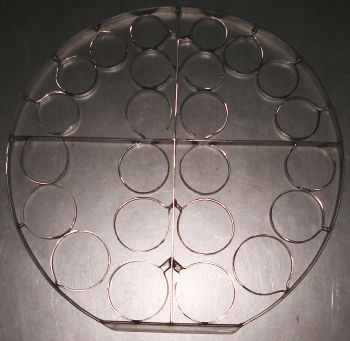 De hele konstruktie
kan worden losgenomen, wat trouwens nodig is om de pijpen te kunnen wegnemen
van de windlade. De pijphouder weegt 6kg, dit komt dus bovenop het gewicht
van Qt.
De hele konstruktie
kan worden losgenomen, wat trouwens nodig is om de pijpen te kunnen wegnemen
van de windlade. De pijphouder weegt 6kg, dit komt dus bovenop het gewicht
van Qt.
- 03.09.2007: Pijphouder verder afgewerkt: uitzagen en lassen verbindingsstuk
naar de kraag van de bovenste windlade, uit inox 30x30x3 warmgewalst hoekprofiel.
Verbindingsgaten 5mm ingeboord, in register met de 4mm gaten in de kraag.
Doorheen deze gaten worden inox verbindingspennen gestoken. Ze mogen beslist
niet worden vastgeschroefd! Vertikale steun voor de pijphouder gelast uit
12mm diameter volstaf geslepen inox met platte aangelaste vork aan bovenzijde
en ingeboord en gelast op een stuk inox plat, 100x30x10. De afstand van de
onderste rand van de pijphouder tot de bovenkant (hout) van de onderste windlade
in exact 600mm. Hartafstand bevestigingsgaten 5mm op de voetplaat: 80mm.
- 04.09.2007: Bevestiging viltjes op de pijphouder. Enerzijds zijn die nodig
om de pijpen tegen krassen te beschermen bij het op- en afnemen van de pijphouder,
anderzijds heffen zij parasitaire trillingen en resonanties op die kunnen
ontstaan tussen pijp en beugel wanneer de pijpen klinken.
- 05.09.2007: Bewerking van de Vlaamsche Leeuw (Karel Miry) voor Qt afgewerkt,
met de hulp van Xavier Verhelst. Nazicht midi bestanden Frank Nuyts. Verder
werk aan 'Cuties for Qt', een kleine suite bestaande uit 'Wouwel', 'Akafest'
en 'Qtree'.
- 06.09.2007: Het lek op pijp 79 komt terug. We zullen die windlade toch weer
moeten openen... Stalen draagberrie uitgebreid met aangelast 30x30x3 profiel
waarop een draagbeugel moet komen voor de voorkant. Deze accessoires zijn
uitsluitend nodig voor de ontoegankelijke zaal van het Gentse konservatorium.
Proefopnames gemaakt van 'Qtree' en 'De Vlaamse Leeuw'. Werksessie met Frank
Nuyts voor diens Qt kompositie.
- 07.09.2007: Start laswerk voorste draagbeugel in gewoon staal (1" buis).
Vlaamse Leeuw voor akkreditatie aan Jan Rispens bezorgd op CD.
- 08.09.2007: Aanlassen draagstang aan berrie. Oplassen M20 moer op 30x30x3
profiel aan de zijde van de draagplaat van de kompressor voor bevestiging
spanklem. Laswerk draagberrie afgewerkt. Klemstuk voor M20 bout nog te maken.
Herziening PIC kode voor het midihub board met stappenmotor besturingen en
melexis sensoren met Johannes Taelman.
- 09.09.2007: Test op draagkracht en doorbuiging van de draagberrie bij een
belasting van 250kg. Ontwerp klemstuk met 20mm gat voor vastklemmen draagberrie
op de 8mm dikke inox draagplaat van de motor.
- 10.09.2007: Test komposities Kristof Lauwers, Sebastian Bradt en mezelf
(Qtree). Aanpassing Alois Haba muziek aan de mogelijkheden van Qt. De geplande
uitwerking van de PIC firmware is uitgesteld vanwege ziekte van Johannes Taelman.
- 11.09.2007: 'De Vlaamse Leeuw' , in een kwarttoonszetting, opgenomen en
als MP3 op de site beschikbaar gesteld: Recording
- 12.09.2007: Verdere afwerking draagberrie voor Qt
- 13.09.2007: Faktuur gekregen voor transport met 6 man naar en terug van
de mierezaal in het konservatorium: 700 Euro. Eigenlijk niet overdreven, gezien
de nodige mankracht.
- 15-16.09.2007: Qt demonstraties voor publiek Festival van Vlaanderen. (ViZit)
- 17.09.2007: Werk van Alois Haba klaargemaakt voor Qt (bewerking Sebastian
Bradt. Bespreking UDP/IP protokol met Johannes Taelman.
- 18.09.2007: Try out koncert.
- 19.09.2007: Verdere afwerking draagberrie. Proefopnames gemaakt van Charles
Ives, Yvan Wysnegradski, Michiel De Malsche, Sebastian Bradt, Frank Nuyts,
Simon De Poorter, Wouter Simoens, Evert Bogaert.
- 20.09.2007: Multiplex drukkussen gelijmd op de draagberrie ter spreiding
van de druk op de voorste as bij het opheffen van het instrument. Kompilatie
klaargemaakt van de trailer-stukjes op Qt voor de akademische opening.
- 22.09.2007: 'Qtree' afgewerkt voor de akademische opening.
- 23.09.2007: Qt weer transportklaar gemaakt voor konservatorium. De vernieuwde
draagberrie lijkt goed te passen. De montagetijd moet wel begroot worden op
telkens ca. 15 minuten. Een 30mm ring/steeksleutel voor de M20 bouten is onontbeerlijk.
- 24.09.2007: Kabelboom boven de pic boards van de hoogste windlade vastgelegd.
Bij demontage moeten de ligaturen wel losgeknipt worden.
- 25.09.2007: Transport van <Qt> naar het konservatorium. Qt speelklaar
gemaakt op het podium.
- 26.09.2007: Natrekken stemming na transport. Kleine korrekties. Akademische
opening suksesvol afgewerkt.
- 27.09.2007: Terugtransport Qt naar Logos. Nazicht werking: o.k.
- 02-15.10.2007: Redaktie software voor de polyphonic key aftertouch.
- 05-22.10.2007: Design and construction of a specific sensor for playing
Qt with body gesture. Article on this
subject placed on this website. New sensor baptised HY1.
- 24.10.2007: Organisatorisch werk i.v.m. de kreaties van de diverse stukken
voor Qt. Kontakteren musici en vastleggen repetitieschemas.
- 26.10.2007: Bestelling bij August Laukhuff van enkele reeksen kegelventieltjes
ter verbetering van de nuanceringsmogelijkeden van de note-aftertouch op de
onderste windlade.
- 02-05.11.2007: Proefprojektje opgezet voor evaluatie van de nieuwe kegelventielen.
Ook hierbij moeten de veren aanzienlijk sterker genomen worden.
- 05.11.2007: Tussentijds onderzoeksrapport opgesteld en overgemaakt aan de
departementsraad van het Konservatorium.
- 06.11.2007: Zoektocht naar inox M2 boutjes met een draadlengte van 30mm.
Dit blijkt helemaal niet standaard verkrijgbaar te zijn. Deze boutjes zijn
nodig voor een verende bevestiging van de kegelventielen op de klepmagneten.
Artikel over 'Expression control
in musical automates' verder uitgewerkt.
- 07-11.11.2007: Verdere ontwikkeling besturingssoftware voor algoritmische
kompositie in GMT door Kristof Lauwers.
- 12-14.11.2007: Werkdagen met Sebastian Lach Lau rond werk voor Qt.
- 15-24.11.2007: Ontwikkeling van een pyrodetektor als bespelingsinterface
voor Qt. Artikel terzake afgewerkt en op de site beschikbaar gesteld:
'Infrared Body Sensing'.
- 25.11.2007: Opmetingen van enkele karakteristieke ventieltrajekten.
- 26-30.11.2007: Proefopnames nieuwe stukken voor Qt.
- 04.12.2007: Werksessie met Barbara Buchowiec voor haar Qt kompositie.
- 05-10.12.2007: Verder werk aan de ontwikkeling van specifieke harmonie funkties
voor kwarttoonskompositie in GMT.
- 11.12.2007: Barbara Buchowiec werk aan 'Mars of the liliqts' voor Qt en
altviool.
- 12-18.12.2007: Muzikale testfaze: kwarttoonsharmonie implementeren in GMT.
- 21-23.12.2007: Tests kwarttoonsharmoniesoftware.
- 03.01.2008: Kompositie van Barbara Buchowiec voor Qt en altviool afgewerkt.
- 04-24.01.2008: Verdere ontwikkeling kwarttoons harmonie binnen <GMT>.
- 25.01.2008: Repetitie planning kompositie Barbara Buchowiec.
- 26.01.2008- 14.02.2008: ontwikkeling software libraries voor de behandeling
van kwarttoonsharmonie binnen de GMT programmeertaal voor algoritmische kompositie.
Een reeks funkties gesteund op de bevindingen van Herman Helmholtz inzake
dissonantie en stemvoering werden geimplementeerd als HH_* funkties binnen
de gekompileerde biblioteek g_har.dll.
- 15.02.2008: Aanbevolen notatie voor kwarttoonsmuziek en de overeenkomst
met fraktionele midi-noten:
 De
traditionele enharmonien ( do# / reb, re# / mib, fa# / solb, sol# / lab, la#
/ sib) kunnen behouden blijven, maar het gebruik van kwarttoons enharmonische
notatie kan absoluut niet aanbevolen worden.
De
traditionele enharmonien ( do# / reb, re# / mib, fa# / solb, sol# / lab, la#
/ sib) kunnen behouden blijven, maar het gebruik van kwarttoons enharmonische
notatie kan absoluut niet aanbevolen worden.
- 17.02.2008: Verder werk aan specifieke kwarttoonsharmonie. Demo stuk in
ontwikkeling: Akafest.
- 19.02.2008: Werksessie mat Qt en Xy Hans Roels. Interview met Kristien Heirman
voor konservatorium over Qt en de week van de hedendaagse muziek in het kader
van de mikrotonaliteit.
- 25.02.2008: Werksessies Qt voor Akafest (gwr), Kristof Lauwers en Hans Roels.
Proofreading Kristien Heirman interview. Preprint.
- 28.02.2008: Werksessie met Kris De Baerdemacker en Yvan Vander Sanden.
- 29.02.2008: Werksessie Kristof Lauwers en Sebastian Bradt.
- 01-02.03.2008: Demo kode toegevoegd voor demonstraties in lezingen over
mikrotonaliteit
- 03.03.2008: Werksessie Kristof Lauwers en Kris De Baerdemacker
- 04.03.2008: Werksessie Barbara Buchowiec
- 05.03.2008: Officiele eerste presentatie van Qt: Week van de hedendaagse
muziek: M&M koncert
- 06.03.2008: Transport Qt naar konservatorium: Middagkoncert met Qt
- 07.03.2008: Qt koncert in de mierezaal van het konservatorium.
- 08.03.2008: Qt heeft zijn inspeling en doop goed doorstaan. Hij is veilig
en wel terug in de tetraeder aangekomen.
- 11.03.2008: Qt speelt een hoofdrol in het M&M 'Young Composers' koncert.
- 12-17.03.2008: Zorgvuldige afscherming van <Qt> voor bouwstof, veroorzaakt
door de verbouwing van de straatzijde van de koncertzaal en het konstruktieatelier.
- 18.03.2008: Voorbereiding lezing over het onderzoeksprojekt rond Qt voor
de Hogeschool.
- 19.03.2008: Lezing over het Qt onderzoeksprojekt voor de navorsers van Hogent,
departementen Akademie en Konservatorium.
- 20.03.2008: Voorstelling van Qt op de wetenschapsdag van Hogent in het konservatorium.
Transport van Qt naar het konservatorium.
- 21.03.2008: Terugkeer Qt. Herstelling beschadigd pijpwerk. Een vijftal pijpen
zijn in het transport ontstemd geraakt.
- 24.04.2008: Qt ingezet in het Glitches koncert.
- 05-08.08.2008: Werksessie op Qt door de portugese komponist Jaime Reis.
- 27.05.2010: Voorbereiding Qt voor een trip naar Alden Biesen (Dag van de
oude muziek).
- 11.01.2012: Klein lek op noot 69 als gevolg van snelle gerepeteerde noten
met heel lage winddruk, waardoor de kleppen toch wat kunnen gaan schuiven.
- 18.09.2013: Qt werd agressief aangevallen door een waslijn tijdens een performance
van Emilie De Vlam. Een pijp sneuvelde en zeven andere raakten grondig ontstemd...
- 20.09.2013: Pijp 99 opnieuw gemaakt en geintoneerd. Stemming van het topoktaaf
rechtgezet.
- 14.12.2013: Lekkende kleppen op pijpen 76 en 54.5 bijgeregeld.
- 27.12.2015: MP3 file van Benjamien Lycke's Bagatelle voor Qt toegevoegd
en opgeladen op de site.
- 14.09.2023: Transport van <Qt> met een groot deel van het robotorkest
naar Berlijn. Luxtax verzorgt het transport. Bestemming: Deutsche Oper Berlin,
voor de Zeroth Law produktie van Gamut Inc. De voorstellingen grepen plaats
op 27,28 en 29 september. Twee pijpen kregen last van een persistent lek dat
we terplekke dienden te verhelpen.
- 02.10.2023: Bij aankomst van het transport met <Puff> uit Berlijn,
bleek het instrument erg zwaar beschadigd te zijn. Klaarblijkelijk werd het
tijdens het transport niet vastgemaakt. Daardoor werden de pijpen op de onderste
windladen zwaar gedeukt en kwamen soldeernaden zelfs helemaal los.
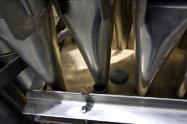
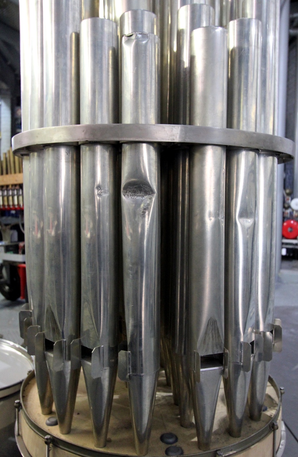
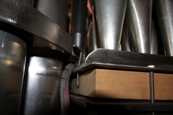
- 09.10.2023: Dieter Potvlieghe gekontakteerd met het oog op restoratie.
- 10.10.2023: Hoge inox M6 moeren die waren afgerammeld aan de lage windlade
opnieuw geplaatst en vastgeschroefd.
- 11.10.2023: Stefan Claessens gekontakteerd, die woont immers in Hamme- heel
wat dichterbij... Stembeurt van alle 'normale' pijpen op 442Hz uitgevoerd.
De pijpen voor de noten 46 en 47 moeten wel nog ontblutst worden en dan uiteraard
opnieuw gestemd.
- 19.10.2023: Persistent lek op pijp 101.5 en 69...
- 21.10.2023: Hoge windlade van alle pijpen ontdaan, losgemaakt en opgetild.
Klep voor noot 101.5 vervangen door een wat groter exemplaar. Klep voor noot
69 bijgebogen en gecheckt op sluiting. Alle pijpen teruggeplaatst en windlade
terug vastgemaakt. De hele operatie neemt zowat 5 uur in beslag. <Qt>
is weer helemaal gezond nu, op de vier pijpen in herstelling na.
- 23.10.2023: Nieuwe blauwe LED spotjes besteld, nu 5 W exemplaren. Opgelet:
in <Qt> zijn die 12 V lampjes in serie geschakeld, voor werking op 24
V.
- 25.10.2023: De vier geblutste en gehavende frontpijpen werden door Stefan
Claessens mooi hersteld teruggebracht. We kunnen Qt weer helemaal in orde
brengen.
- 31.10.2023: De nieuwe 'blauwe' lampjes zijn een ontgoocheling... Dit kunnen
we geen blauw noemen, hooguit blauwig hard wit.
- 03.11.2023: <Qt> volledig gestemd: diapason 440 Hz and 452 Hz for
the quartertones. Pijphouder voor de voorste pijpen nog niet teruggeplaatst,
die is voor de opstelling in de Tetraeder ook helemaal niet nodig. Qt terug
op zijn reguliere plaats in het orkest gebracht, een operatie die zowat een
uur in beslag neemt.
Nog verder af te werken komponenten en nog uit te voeren research:
- Ontwikkeling kode binnen de Microchip C-compiler voor de verwerking van
de data van de Melexis sensoren.
- Veertjes vervangen en afregelen op onderste windlade.
- Opstellen tabellen met de relatie winddruk en toonhoogte voor de opgesneden
en gestemde pijpen. Vergelijking opstellen voor implementatie in de algoritmiek
van GMT. (Gausfit).
- Opname regelkarakteristiek van de gemonteerde ventielen en de overeenkomstige
sensorsignalen.
- Programmeren van de kode voor de klepmotorbesturings PIC. (18F2525). Implementatie
van channel pressure.
- Evaluatie van de parameterisering van de time kode op PIC nivo.
- Assembler kode ontwikkelen voor de aftertouch in de noten-PIC's
- PIC's definitief programmeren (12) (Flash)
- Opmeten van de werkelijke pijplengtes en aanvullen van de mensuurtabel.
- Bouw van een dubbel keyboard voor manuele bespeling.
- Aanmaak uitvoerige gebruikers handleiding.
Technical data and circuit drawings:
- Power: 230 V ac - 50 Hz - 950 Watt (peak). The instrument must be grounded.
- Wind pressure: 10-150 mm H2O (1 to 15mBar) Nominal
pressure: 145 mmH20, for 440 Hz tuning at 20 degrees
Celsius.
- Reaction time for compressor motor speed change commands: 8 ms
- Microprocessors: 18 chips: (PIC18F2525 (1), PIC18F4620(9), PIC18LF4620(3),
Melexis-DSP(2), Sanyo Motor ctrl (2), Leroy Controller (1))
- Size: length: 2000 mm, width: 700 mm, height: 1760 mm.
- Insurance value: 74.500 Euro (final production cost)
- Metal weigth of the pipes: 56 kg
- Total Weigth: 226 kg. The instrument cannot be lifted up nor carried by
people. During transport, it should always be kept in a full horizontal position.
Ramps should be used to overcome small steps.
Ordering
data and parts list for essential components used in the construction:
Wiring diagram for the midihub board in QT:
Wiring diagram for the windvalve controls:
Analog 5V power supply:
Power supplies:
Motor Controller signals:
- T1 = 0V [ black wire to midi hub board]
- T2 = A1 remote analog speed reference voltage (0-10V, Zi=100k Ohm) [ white/red
wire to midi hub board]
- T3 = + 10 V reference voltage output, 5mA max. [ pink wire to midi hub board]
- T4 = A2 local analog speed reference voltage (0-10V) [not used by us]
- T5, T6 fault relais [not used by us]
- B1 = analog output voltage proportional to actual motor speed (0-10V, 5mA
max, 0.1% resolution)
- B2 = +24V DC output for logic switch signals, 100mA max [ red wire to midi
hub board]
- B3 = digital output - zero speed indicator ( 0 / 24V) [not used]
- B4 = drive enable/reset. Must be HIGH (+24V) if the motor is to run. [white/black
wire to midi hub board]
- B5 = Run Forward.. Must be high for forward run (+24V) [ green wire to midi
hub board]
- B6 = Run Reverse. [ not used by us]
- B7 = If HIGH , A2 input is selected. If LOW, A1 input will be used. Must
be LOW in our application.
Motor controller parameters (parameters not mentioned here retain their default
value)
- Pr1 = 0 minimum speed
- Pr2 = 65 maximum speed (Hz) [07.08.2006]
- Pr3 = 5.0 seconds, acceleration rate (in seconds per 100Hz)
- Pr4 = 10.0 seconds, deceleration rate
- Pr5 = AV.Pr, drive config, voltage input and 3 preset speeds.
- Pr6 = 1.5A motor rated current
- Pr7 = 2800 rpm, motor rated speed
- Pr8 = 230V, motor rated voltage
- Pr9 = 0.85, motor power factor
- Pr10 = parameter access level: set to L3 to get access to all parameters.
- Pr16 = Volt, analog input mode, set A1 to 0-10V
- Pr 29 = Europe
- Pr31 = 2, stop ramp mode: stop with 1s DC injection to brake.
- Pr37 = 12kHz, maximum switching frequency
- Pr38 = 1, non-rotating static autotune
- Pr39 = 50Hz, motor rated frequency
Wiring
tables and color coding for the lower and upper windchests
Power supply requirements:
- Hold power supply: 10.8V/12V - 50A, allowing for complete clusters. (P=
360Watt). Fan disabled.
- Velo-pulse power supply (24V - 6A) : Siemens Sitop 24V/10A, positive pole
grounded.
- Tremulant stepping motor & lights power: (24V - 6A): Siemens Sitop 24V/10A,
negative pole at ground.
- Logic power: 5V / 3A (3 separate analog 1A regulators)
- Analog Power: 10V/ 20mA (delivered by motor controller)
- 24V logic power: 24V/100mA (delivered by motor controller)
Lay out of the pipes on the windchests:
Assembly and disassembly instructions and remarks:
If the high windchest has to be opened, always first remove all pipes. Next
remove the connectors from the boards K2-K6 and Q2-Q6. Now, using a hex key,
unloosen the 80mm long M6 bolts (never turn the nuts!). Number the nuts and
put them in a safe place: they are individually different (long stainless steel
bus-connection nuts with one end cut under a variable angle between 30 and 45
degrees) and have to be reassembled the same way. Remove the tending rim and
put it aside. Now loosen the windchest gently. Dont insert screwdrivers in the
gap since that will lead to permanent damage and leaks. If a tool seems required,
use a 40cm long, 50mm wide and 2mm thick blade of stainless steel with rounded
edges. The windchest only has to be opened in the following cases: to repair
persistent leaking pads, to get access to the tremulant valve, to repair solenoid
valves that burnt out as a result of an external short circuit or a software
failure. It takes two people to lift the windchest vertically and flip it over.
Take care not to touch the pads. They get very easily misalligned.
All pipes are marked on the right side of the labium. C0 corresponds to pipe
36. All quartertone pipes are marked with an additional + sign.. Thus c''+ means
pipe 60.5. If pipes are removed they have to be handled very carefully. Put
them in low crates on a soft woolen surface. Do never stack them in top of each
other. Never touch the tuning ears nor lean the pipes against them.
Last update: 2023-11-03 by Godfried-Willem Raes