
<Troms>
an automated percussion robot
Godfried-Willem Raes, 2000
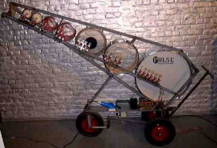
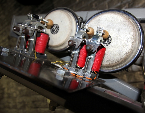
This instrument is a computer controlled assembly of seven single skin drums of increasing sizes (from 70 cm to 7 cm) . Each drum has a set of different beaters. Since the smallest drums do not have enough place to accomodate a large number of beaters, this number decreases with the size of the drums. The beaters are arranged such that the rightmost beater always hits the center of the drumskin. The leftmost beater is positioned such as to obtain a rimshot. Other beaters occupy intermediate positions. The drums are mounted in an assembly with an angle of 36 degrees, on a sturdy three-wheel base.
The complete structure is made of steel and was almost entirelly welded using TIG technology. The instrument can be played by standard MIDI commands. (midi implementation given below).
The picture above gives an idea about the way the instrument is build. Although the picture was taken when the instrument was fully functional, it was not completely finished. Still some elements had to be properly welded and the whole skeleton still needed to be painted. A small cymbal (missing on the picture) was added in 2004.
This instrument was made and designed to be a part of the <Slag-Werk> project realized for 'Web Strikes Back' at the occasion of the Tromp biannual, october 2000 in Eindhoven, the Netherlands. In 2004 the instrument has undergone a major revision: a solenoid driven damper as well as a heavy soft mallet on the inside of the bass drum and a small cymbal were added. The power supply voltage was increased in order to get a wider dynamic range and even faster response times. Lights have been added as an extra visual feature. Last but not least, the automat now is controlled by two PIC processors and listens to midi commands directly. In the original version, a laptop computer with a parallel printer port was required to control the functions of this automat.
<Troms> uses dedicated hardware and firmware, designed for musical automats such as player pianos, percussion instruments, organs and even bowed instruments. Details can be found in the many webpages on this site describing the individual musical robots. Here is a list.
The hardware for <Troms> consists of following printed circuit boards:
1. A small midi input and buffering board, housing the optocoupler and two hex inverter chips so that we provide 3 midi thru signals available for cascading to other robots.
2. two PIC controller boards (similar type, pulse board version 1, as used for <Puff>). These boards get their input from a midi input signal. The circuit looks like:
This is a sketch of the PCB: 
3. The power mosfets we used for controlling these solenoids are Harris RFP4N12L or IRL640, since these switch on TTL levels. Note that when the power suppy is switched on, all latches may go to an arbitrary logic state during startup of the processors, thus sounding arbitrary notes and drums at the same time. To avoid this, we connected the 5 V power supply to the mains before the power switch. In case a controller reset is required, the power cord must be disconnected, the power switch in the off position and then back on.
4. The power supply for this instrument is rated for 240 Watts. The instrument can also be taken on the road, running from a 12 Volt car battery and a voltage inverter. The power supply circuit is straightforward, and consists of three parts: 5 V / 300 mA for the PIC controllers and logic -a standard 7805 circuit-, 24 V / 3 A, using an industrial standard SMPS power supply and 60 V / 3 A for the velocity controlled beaters, dimensioned for the high currents involved when all hammers do strike. The bulb in the circuit is a surge protector and under normal operating conditions this bulb will not even glow. Although this voltage is not stabilized, it will not fluctuate more than 8 Volt, since the load is always switched in a serial way, even when commands are given to sound all drums together at their maximum force. The high value of the buffer cap (22 mF) is of course essential to get this result. The pulse duration for the hammer solenoids is limited in the PIC firmware to 25 ms, corresponding to a midi velocity value of 127. The soft-beater has a twice as large range (1-64 ms), to compensate for the high mass of the beater.
The construction drawing for the wheel base looks like:
Music:
If you are using <GMT> under Power Basic, you can
use all specific hardware control functions and procedures provided in
our library. The midi mapping is: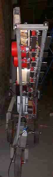
- Bass-drum: midinotes 24,25,26,27,28,29 [beaters from center to rim] , soft beater: 23.
- Tenor-drum: midi notes 30,31,32,33 [beaters from center to rim]
- Side-drum: midi notes 34,35,36,37 [beaters from center to rim]
- Low-bongo: midi notes 38,39,40 [beaters from center to rim]
- High-bongo: midi notes 41,42,43 [beaters from center to rim]
- Low LP mini bongo: midi notes 44, 45 [center beater and rimshot beater]
- High LP mini bongo : midi notes 46,47 [center beater and rimshot beater]
- Cymbal: midi note 48
The midi channel to be used for <Troms> is 6. (7 if counting from 1).
Coding samples can be found in the <GMT> module troms.inc. Specific compositions for <Troms> have been written by Godfried-Willem Raes (Afrotroms, E-Troms, GeroTroms, Ratrom, Simple Triple Ouxercuse, Seven Quaver Evertire), Michael Manion and Kristof Lauwers (Betatroms and StochTroms).
For those who like more to see things in traditional music notation:
The sounding pitches (approximate) are indicated in red notes. Of course these depend slightly on temperature and stretching of the membranes. The drums should not be considered a pitched instrument. When two notes are given, they represent the strongest pitchband and the next strongest.
Complete midi implementation table:
Troms listens to midi-commands on channel 6 (offset zero).
| Midi Note Command: | function | implementation | remarks |
| 18 | light inside bassdrum | note on / note off - no velocity | 10Watt bulb - 24V |
| 19 | light inside tenordrum | note on / note off - no velocity | 5 Watt bulb - 24V |
| 20 | light inside middle drum | note on / note off - no velocity | 5 Watt bulb - 24V |
| 21 | bassdrum damper |
note on -no velocity note off with release |
note off with a non-zero release value triggers a pulse to move the damper away from the drumskin (24V) |
| 22 | bassdrum damper return | none | for internal use only |
| 23 | bassdrum soft beater | note on + velocity | note off not required |
| 24 | bassdrum centrum beater cork | note on + velocity |
note off not required to play drumrolls, alternate beaters |
| 25 | bassdrum cork beater | note on + velocity | note off not required |
| 26 | bassdrum corkbeater | note on + velocity | note off not required |
| 27 | bassdrum woodbeater | note on + velocity | note off not required |
| 28 | bassdrum woodbeater | note on + velocity | note off not required |
| 29 | bassdrum woodbeater near rim | note on + velocity | note off not required |
| 30 | tenor drum center beater | note on + velocity |
note off not required to play drumrolls, alternate beaters |
| 31 | tenor drum | note on + velocity | note off not required |
| 32 | tenor drum | note on + velocity | note off not required |
| 33 | tenor drum beater near rim | note on + velocity | note off not required |
| 34 | center drum, center beater | note on + velocity | to play drumrolls, alternate beaters |
| 35 | center drum | note on + velocity | note off not required |
| 36 | center drum | note on + velocity | note off not required |
| 37 | center drum beater near rim | note on + velocity | note off not required |
| 38 | low red bongo center beater | note on + velocity |
note off not required to play drumrolls, alternate beaters |
| 39 | low red bongo middle beater | note on + velocity | note off not required |
| 40 | low red bongo rim beater | note on + velocity | note off not required |
| 41 | high red bongo center beater | note on + velocity |
note off not required to play drumrolls, alternate beaters |
| 42 | high red bongo middle beater | note on + velocity | note off not required |
| 43 | high red bongo rim beater | note on + velocity | note off not required |
| 44 | minibongo low center beater | note on + velocity | to play drumrolls, alternate beaters |
| 45 | minibongo low rim beater | note on + velocity | note off not required |
| 46 | minibongo high center beater | note on + velocity | to play drumrolls, alternate beaters |
| 47 | minibongo high rim beater | note on + velocity | note off not required |
| 48 | cymbal beater | note on + velocity | note off not required |
| 49 | as yet not used | note on + velocity | note off not required |
| Key-pressure | implemented for the notes 23 to 49 | note byte + repetition speed | note off stops the repetitions. |
| Controllers | |||
| #30 | sets all repetitions rates to one and the same value. |
0 = cancel repetitions 1-127 = repetition speed |
can be overriden by key-pressure commands |
| #66 | power on/off | not required for operation, but the command also resets all controllers | |
| #69 | light automation |
selects automated light shows value 0 switches light shows off |
to use the lights normally, reset this controller. By default it is set to 1 Possible values are 1,2,3,4,5. |
| #123 | all notes off command | resets all beaters, lights, dampers... | |
| Program Change | program numbers 0, 120-127 can be used to select different velocity scalings | The velocity scalings can be programmed using sysex commands. |
default program number is always 0. We dropped program change since the 2022 revision of the firmware. |
PIC1 controls the notes 18 to 33, PIC2 does notes 34 to 49. Note 49 has no function yet and is implemented for later upgrades only.
construction workshop & low level coding collaborators:
- Kristof Lauwers (GMT coding)
- Filip Switters (TIG welding)
- Xavier Verhelst (purchasing)
- Johannes Taelman (PIC programming, revision 2004 & revision 2006)
- Bert Vandekerckhove (maintenance)
- Godfried-Willem Raes (design, PIC coding revision and upgrade 2022 and later)
Dimensions:
- width: 2500 mm
- height: 1860mm
- depth: 600mm
- weigth: 80kg
- power consumption: 240 Watts / 230 V AC (peak). Under normal and averaged working conditions: 50 Watt.
- data input: MIDI input.
- data outputs: 3 x midi THRU. (unmodified signal)
Insurance value: 8.500 Euro.
| Back to M&M ensemble | Back to Web Strikes Back | Back to logos' main index page | To homepage Godfried-Willem Raes |
The <Troms> automat can be heard on the Logos Public Domain CD <Automaton> (LPD007). as well as a robot in the M&M orchestra on Logos Public Domain CD <M&M> (LPD008)., Machine Orchestra, (LPD13) , and Robodies (LPD014).
Last update: 2024-12-22

Maintenance notes:
Technical note: As soon and as long as Troms is connected to the mains power, the internal 5 V power supply will be switched on. Thus, if for any reason a cold reset is required, the instrument has to be completely unplugged. The lever switch is used to switch the high voltage power supplies (24 V for the lights and 60 V for the solenoids). When not in use, this switch should be in the OFF position. The metal construction of Troms is connected to the mains ground, as dictated by electric safety regulations. However, due to the naked construction, parts carrying relatively high voltages can be touched. Therefore audiences and public should never be allowed to touch any part of the robot.
At our own premisses, the entire collection of musical robots is powered
via a 5 kW separation transformer.
Bulb in power supply: Osram Xenophot, 36V/ 400W type number HLX64664
(serves as a fuse only). This bulb should never even glow up!!!
Microprocessors: Microchip PIC18F2525, firmware version: 16.12.2022, for PIC1 and 22.10.2023, for PIC2. (previous version was 25.10.2006).
Hex dumps for the microprocessors:
Logbook:
- 15.05.2000: <Troms> is up and working. The robot is controlled through an 8-bit parallel bus using a modified Centronics protocol.
- 12.05.2004: PIC boards installed and programmed to allow for direct
MIDI control. The two PIC microprocessors are 18F252 I/SP.
This is the mapping:
- 20.10.2006: failure on note 28, bass drum. Apparently PIC1 crash! New pic programmed. Midi input circuitry improved using a 6N137 optocoupler and two 74HCT14 buffers. This small extra board now found a place inside the mains switch box where also the 5V power supply is located. Midi signal monitoring green LED's added on both PIC boards.
- 22.10.2006: Power supply for solenoids changed. Voltage is now ca. 59 V. (under no load: 62.5 V, with a high velo and drum density load: 54 V. The dynamic range is now 6 dB larger than in the previous version. Duty cycle should now not exceed 20% when the highest velocity values are used.
- 23.10.2006: Test session by Kristof Lauwers. To do: upgrade PIC's to 18F2525 and add provisions for sysex rescaling of velocities.
- 25.10.2006: PICS upgraded to 18F2525. New firmware uploaded, sysex programmable lookup tables for the velocity scalings are now implemented. Pin code word for sysex: 'trom'. The timing resolution for a unit value in the lookup tables is now 27.2µs. The damper return pulse is now generated when a note off command with a release value is passed for note 21.
- 26.10.2006: Test and torture session by Godfried-Willem Raes.
- 25.04.2007: Troms presented at the Jauna Muzika festival in Vilnius. Returned on may 2nd.
- 23.05.2008: Troms presented in Amsterdam (Orgelpark).
- 29.08.2008: Failure on PIC 1. None of the notes 18-33 work and the PIC became extremely hot...
- 01.09.2008: PIC replaced and reprogrammed.
- 20.08.2009: Due to a crash of PIC1 , the solenoid for note 32 burned out completely. Solenoid needs to be replaced. The Osram Xenophot bulb functioned as intended.
- 21.08.2009: Mosfet for note 32 replaced (IRL640). We could not find any reason for the failure. Solenoid and hammer replaced. Small 100 nF cap placed over the high voltage connection on PIC1 board.
- 20.04.2013: <Troms> survived the trip to Glasgow very well! We expect it back in Ghent on monday 22nd of april.
- 23.04.2013: Troms came back in perfect condition after his trip to Glasgow.
- 09.08.2014: Solenoid for beater note 24, the lowest one on the bassdrum, replaced as the metal hook on the anchor holding the beater shaft broke off. Material fatigue we guess. After all, this beater -certainly the most used- has been in operation for 14 years, playing every day!
- 20.04.2015: The skin on the high red bongo found perforated by the beater... As we didn't have a transparent spare skin, we replaced it with a darbukkah skin. This is a lot thinner than the original and thus may not last very long.
- 26.09.2016: <Troms> transported to Berlin for participation in the 'Wir sind die Roboter' Festival.
- 02.10.2016: <Troms> returned safely from Berlin. There seems to be an issue with PIC1 as it had to be rebooted several times before it worked properly. Aging of flash memory? Maybe we should consider a major rewrite of the firmware.
- 03.10.2016: <Troms> checked and found to work O.K. No changes performed.
- 28.10.2016: <Troms> on the road to Bruges for Iedereen Klassiek.
- 30.10.2016: Returned safely from Bruges, concertgebouw.
- 15.12.2022: The solenoid hammer for note 29 burned out completely and caused a failure on the entire board controlling the bass side of the robot. Solenoid needs to be replaced. The Osram Xenophot bulb functioned once again as intended. So, once more a failure on the PIC1 board it seems. We started rewriting this firmware from the bottom up again, working further on the achievements reached with <Steely>.
- 16.12.2022: PIC1 board placed back into the robot. Pulse range is now 2 ms to 32 ms for the midi range 1-127. There is a death time (twice the duration of the velo-pulse) programmed now after every pulse, so back to back note-on commands can no longer burn the solenoids. The robot will refuse to play the notes in such cases. The loopspeed in the main processor loop is now 135 kHz with no load going down to 100 kHz at very heavy load and all timer pulses active. We also have to apply this coding to PIC2. The burned solenoid also still needs replacement. Work on the firmware for both PIC's finished and tested by the end of the day. Program change deleted from the midi implementation, idem for the sys-ex.
- 17.12.2022: Both PIC's replaced with new ones and new firmware. Adding
an implementation of automated lights in the firmware for the first
PIC. To be tested.
- 14.09.2023: Troms prepared for transportation to Berlin. One of the
hammers found to be broken off. We replaced the solenoid. Material fatigue
must be the cause.
- 15.09.2023: <Troms> on the road to Berlin. Destination: Deutsche Oper.
- 02.10.2023: <Troms> returned safely from Berlin. Only the darbukah skin on one of the bongos was found to be perforated. However, this cannot be attributed to transportation. It must have happened during the performances in Berlin. The weakness of this skin was anticipated on 20.04.2015.
- 06.10.2023: Drumskin replaced with a regular bongo skin, as we did not have a thin darbukah skin in stock.
- 19.10.2023: Anomaly reported with stuck note repeats. Most likely we have to do with shaky midi or a failure of the optocoupler on the midi-input board. To be further investigated.
- 22.10.2023: Drumskin for the drum sounding notes 41,42,43 replaced again with a nylon darbukah skin. The uggly brandname on the skin could be removed with some acetone. It's not really a suitable skin, as the rim is too small for a bongo-type drum body. For this reason we had to replace the holding and tuning bolts with longer types. Unfortunately, these bolts have anachronistic imperial size threads. PIC2 reprogrammed: the repeating-notes bug seems cured now. However, for some reason the watchdog LED on the PCB is not flashing, whereas it is, on our debug and programming board...
- 21.12.2024: Beater and solenoid for note 26 on the bass drum replaced. Material fatigue on the hammer-holder hooks caused the hammer to break from the solenoid. We replaced the complete assembly although the solenoid itself was perfectly o.k. At the occasion of this repair we noticed that the skin for the second drum needs to be replaced as well.
- 22.12.2024: Skin for the second largest drum replaced. Diameter 40 cm, transparent.