|

departement muziek &
drama
|
|
<Aeio>
an automated and interactive aeolian cello robot
Godfried-Willem RAES
2007-2018
|
<Aeio>
The first bowed instrument robot we designed was <Hurdy>,
an automated hurdy gurdy, built between 2004 and 2007. The building of that robot
had many problems and our attempts to solve these have lead to many new ideas
and experiments regarding acoustic sound production from bowed strings. The problems
with <Hurdy> were all related to the very complicated controls required
for the bowing mechanism: a system with so many degrees of freedom that handling
it became far from 'automatic' and the users were left with a very complicated
command set in order to make <Hurdy> play the notes he wanted. Bow pressure
curve in time, bowing speed, finger pressure, bowing angle all in function of
the note to be played and the required dynamic had to be send to the robot. To
avoid this we provided the users an alternative way of producing bowed sound from
the string: magnetic drive. This worked very well and many aspects of bowing technique
in <Hurdy> could be automated in a more user friendly way.
These experiments made us dream of an instrument using twelve
strings, in a chromatic arrangement, that would all individually be bowed with
our electromagnetic system. So on the drawing table we envisaged an instrument
with twelve strings tuned from 36 to 47 and equipped with felt covered solenoid
driven dampers. The soundboard could be made from either hardened brass, titanium
or Styrofoam mounted in a steel frame. Now one would think the instrument could
only play twelve notes, but that's wrong since on each string we can sound the
fundamental as well as the entire series of slightly inharmonic partials. In
fact the range is extremely extended and covers at least the ambitus of the
classical cello. The name of this robot was derived from its working principle,
showing some similarity to the aeolian harp, where the strings are struck by
the passing wind. <Aeio> lends itself not only as a robotic instrument
in the context of our Logos robot orchestra, but can also stand very well on
its own as an interactive audio art installation. To render this aspect even
more fruitfull, we added a radar sensor and a processing unit for gesture recognition
to the robot in 2017.
The basic midi note mapping is:
When the instrument is used monophonically, there are no limitations.
However, when you want to play double strings, these can only be played if the
requested notes can be produced on two different strings. That's quite the same
with all usual bowed string instruments. The driver software will arbitrate
for you but there is an obvious possibility that certain chords will not be
sounded in full. All strings can be made to sound simultaneously, if required.
Vibrato, as common on bowed instruments, as well as glissando playing, is impossible
with <aeio>.
A scheme for playing string spectra using midi is to be worked
out. Unfortunately, standard midi has no codification for fractional midi notes
nor for 'just' intoned intervals. So the best alternative seems to be implementing
continuous controllers (say nrs. 36-47) for each string, whereby the parameter
value corresponds to the number of the overtone to be sounded. To also control
the volume or excitation level of the string, we could implement another series
of controllers, say in the range 49-60.
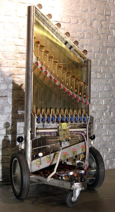
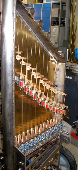
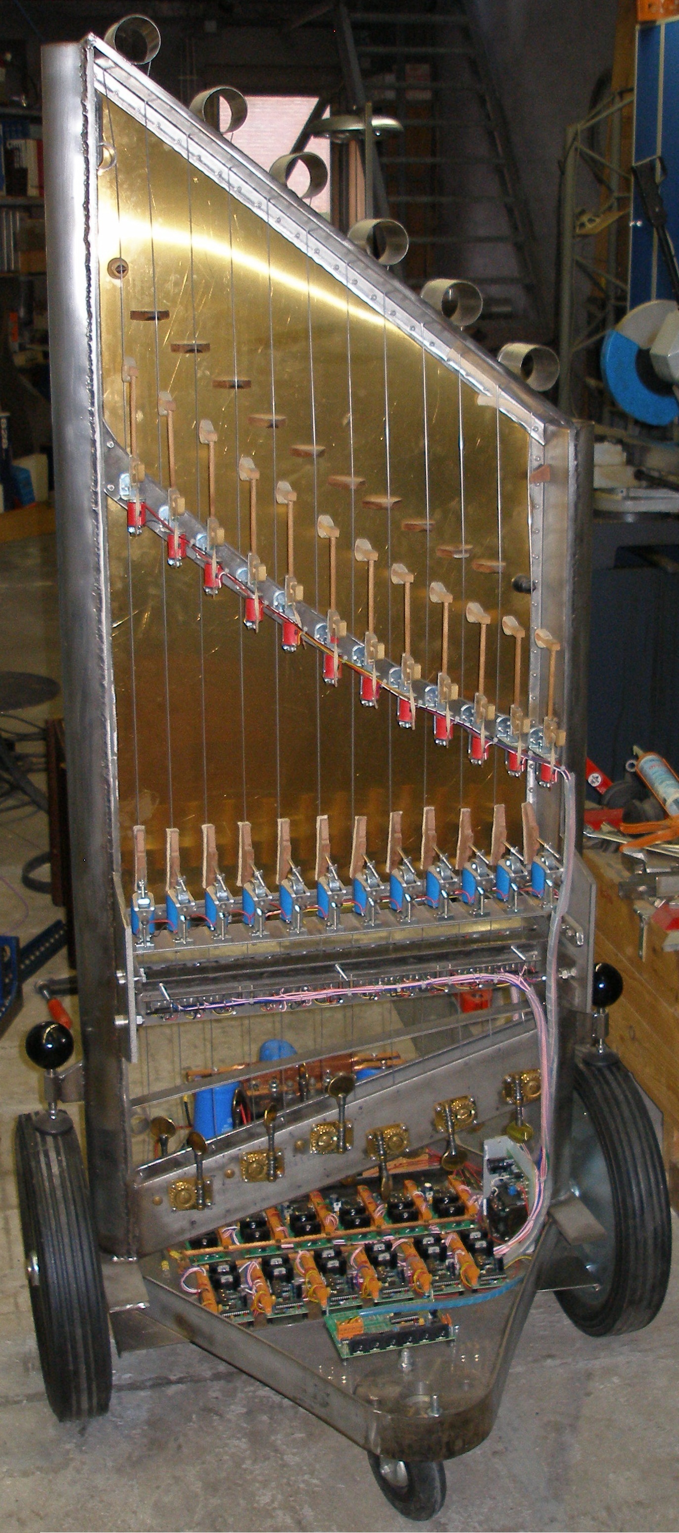
The constructional parts for this robot are all made from welded stainless steel.
The instrument is mounted on a wheel base, as most of our music robots.
The circuitry for each one of the string drivers follows the
schematic drawing below:
Note that the Mosfets need to be cooled, even though they can
withstand up to 41 Amps! A feature around the wiring of the electromagnets in
our initial hardware version is that we tried recycling the energy stored in
the magnet when switched to re-energize it, instead of just absorbing this energy
in the usual diode. This trick only became possible because of using line transformers
as electromagnets in this first version. However, many of the modified line
transformers burned out through the first experimenting sessions and we replaced
most of them with newly wound windings on the same mu-metal cores.
The dampers are controlled by the same PIC microcontroller, a dsPIC30F3010.
The dampers are activated on reception of the note off command for the corresponding
string. De noteoff-release value controls the time the dampers stay in contact
with the string after a note-off. This time interval is interrupted on reception
of a new note-on request for the same string. By setting controller 64 to %true,
the damper mechanism can be disabled for all strings. On startup the mechanism
is always enabled.
|
All sizes essential to the acoustic design and the practical construction
of the <Aeio> robot are given in the very first (distorted) design
sketch to the right. |
:
|
|
|
The shape of the final design differs quite a bit from these first sketches,
but the essential proportions have remained the same.
The strings are driven by the electromagnets in two phases. The signals and
their effect on the string can be depicted as: By extending the duration of the B-states the excitation characteristics of
the string can be modified to a great extend. The duration of the B phase should
never be smaller than the time the string needs to come back to its central
position. Thus the duty cycle for the signals can be limited to 25%. In practice
the above drawing of the string movement is idealized for pure fundamental resonance.
This will only happen at very low excitation levels. When the string excursions
become larger due to a larger magnetization force, the spring action of the
string has to be taken into acount. This explains the zero-cross of the movement
in the B phases as shown in the drawing below:
By extending the duration of the B-states the excitation characteristics of
the string can be modified to a great extend. The duration of the B phase should
never be smaller than the time the string needs to come back to its central
position. Thus the duty cycle for the signals can be limited to 25%. In practice
the above drawing of the string movement is idealized for pure fundamental resonance.
This will only happen at very low excitation levels. When the string excursions
become larger due to a larger magnetization force, the spring action of the
string has to be taken into acount. This explains the zero-cross of the movement
in the B phases as shown in the drawing below:
It will be clear that the waveform thus obtained comes closer to that of a real
bowed string, exactly what we were looking after in the design of this robot.
The firmware in each of the twelve PIC controllers has two cascaded 16 bit timers.
Using the thus obtained 32 bit timer, a period time T can be programmed. For
the fundamental of the string, T should be 1/f in real-world time units. Now
we state T = ta1 + tb1 + ta2 + tb2. Furthermore we state ta1 + tb1 = ta2 + tb2.
For the research version we implemented two separate parameters to controll
the duration of ta1 and ta2 indepently but within the constraints given. In
the definitive version this should become a single parameter controlling the
ratio ta1/ta2. Using this controller, a wide range of influence is gained over
the timbre of the produced sound. To make research and development easier, we
designed the firmware for the string drivers such that each dsPIC processor
responds to its own midi channel, thus using up 12 midi channels. In normal
use, the parser microcontroller (a 16 bit PIC, type 24EP128MC202) takes care
of string arbitration and the user sends all commands on the <Aeio> channel
solely. This is the circuit for the parser board: 
Midi implementation and mapping:
| |
|
- Midi note range: 36 - 127. Velocity implemented.
- Notes 24-35: Exciter beaters. Velocity implemented.
- Note Off commands are required (dampers) . Release value implemented
if controller 65 is true and 64 is false.
- Key pressure: implemented for each string. For
the lights, key pressure steers the flashing speed.
- Controller 7: Master volume controller. Upper limit for the ebow power.
- Controller 20: global flashing frequency for the lights.
- Controllers 30-41: bowing symmetry for each string (default = 64)
- Controller 64, sustain (dampers on or off, 0 = dampers active, >1
= sustain, dampers off)
- Controller 65: note-off release value enable/disable switch. If note
off with release is not used, the value passed with this controller
determines the time the dampers will stay on the string after a note
off.
- Controller 66: power on/off switch (e-bow power
and lights)
- Controllers 50-61: set the tuning base for the strings. Users do not
have to set these controllers since the firmware sets the correct default
to the string tuning.
- Controllers 70-79: used to set parameters for the radar system. For
details, consult the table at the end of this webpage. Controller 79
must be set to >0 to disable the radar. These controllers are only
relevant when the midi input is fed to the radar board. If midi is connected
to the parserboard, the radar is disabled altogether.
- Controllers 80-91: adjust the fine tuning for every individual string
- Controllers 100-111: set the flageolet multiplier value for a string
whilst it is sounding a note.
- Controllers 114-119: set the durations for the embedded compositions
1 - 5, if radar is enabled.
- Controller 123: all notes off ( also switches off the lights)
- Program Change: select different frequency lookup tables (default
= 2, empirical series)
- 0 = platonic series
- 1 = scientific series, after the second degree equation for string
overtones
- 2 = empirical series, after measurement of best resonance
- 3 = closest possible approximation for equal temperament
- 16 = selects embedded composition #1 if radar is enabled
- 17 = selects embedded composition #2
- 18 = selects embedded composition #3
- 19 = selects embedded composition #4
- 20 = selects embedded composition #5
- Lights: (ON/OFF)
- Note 1 = blue LED on the parser board
- Note 2 = bright red LED strip under damper
assembly
- Note 3 = to be mounted
- Note 4 = to be mounted
- Note 5 = yellow LED spot, bass side
- Note 6 = yellow LED spot, trebble side
- Midi Channel: 1 (counting 0-15)
|
Technical specifications:
- sizes: height: 1700 mm, depth 915 mm, width: 810 mm.
- weight: estimated ca. 100 kg
- power: 235V / 700W
- tuning: strictly required before playing. (Normally A=440) . The instrument
can be used for tuning since it has built in references. The GMT-aeio test
code can be used for easy tuning.
- strings: hardened spring steel, diameter 1.5 mm
- Ambitus: midi note 36 -127
- Loudness level: to be determined. (tentatively 0 - 82 dBA)
- Radar frequency used: 10.587 GHz. Range: <= 10 m , 120 degrees in the
horizontal plane.
- If <Aeio> is operated on its own, without external computer connected,
it will behave as an autonomous robot, controlled by gesture and performing
the embedded interactive compositions by Godfried-Willem Raes and Kristof
Lauwers.
- Insurance value: 23.500 Euro
Design and construction: dr.Godfried-Willem
Raes (2007-2017)
Collaborators on the construction of this robot:
- Johannes Taelman (firmware dsPIC controllers)
- Xavier Verhelst (requisites research)
- Kristof Lauwers (application code)
- Troy Rogers (test software, research)
- Lara Van Wynsberghe (embedded fileplayer and tuning aid)
- Laura Maes (documentation)
Music composed for <Aeio>:
Kristof Lauwers "x16.09.2010" (premiere on 16.09.2010)
- Godfried-Willem Raes "Namuda Study: Aeio", 2012, premiered by
Dominica Eyckmans.
- Lara Van Wynsberghe "Oorsprong" (also includes <Rodo>),
03.2015
Specific pieces for <Aeio>'s participation in the
musical robot exhibition at the Speelklok Museum in Utrecht, and specific hardware/firmware
to run them has been developped in 2018..
Embedded interactive compositions:
- Godfried-Willem Raes 'Radaeio' (2017) (3') [embedded composition #1]
- Godfried-Willem Raes 'Aeio Rising' (2017) (3') [embedded composition #2]
- Kristof Lauwers in the works (2017) (3') [embedded composition #3]
- Godfried-Willem Raes 'Aeio Sinking' (2017) (3') [embedded composition #4]
- Godfried-Willem Raes 'Aeio's Response' (2017) (3') [embedded composition
#5]
Nederlands:
<Aeio>
Voor het Logos Robotorkest hadden we reeds in 2004 een automatisch
strijkinstrument gebouwd: <Hurdy>, de automatische draailier. Dat stelde
heel wat meer problemen dan aanvankelijk verwacht. Het strijkmechanisme kende
dermate veel vrijheidsgraden dat de besturing van deze robot bijzonder ingewikkeld
was. Jarenlang hebben we gezocht op betere mechanismen om snaren te strijken
met een goede kontrole over de toonvorming. Erg vele experimenten bouwden we
op en rekenden we van onder tot boven na. Dat leidde in 2007 tot de definitieve
toevoeging van elektromagnetische snaaraansturingen op <Hurdy>, maar meteen
ook tot een boel nieuwe ideeen voor potentieel verder te ontwikkelen strijkrobots.
Zo kwamen we op de idee een soort 'aeolische' cello te bouwen. Deze robot werd
ontworpen met twaalf kromatisch gestemde snaren. Vanaf midi noot 36 tot en met
47. Een toets of een tangentenmechanisme met fretten wilden we niet nog eens
gaan bouwen. Nu lijkt een tessituur van een enkel oktaaf wel wat weinig om van
een cello te kunnen spreken, ware het niet dat ons mechanisme , ook zonder gebruikmaking
van inkorting van de snaren, in staat is ook alle boventonen van die twaalf
noten te laten klinken. Zo kunnen we de gehele tessituur bestrijken. Om de expressiemogelijkheden
niet te eenzijdig te maken, voorzien we elke snaar van een individuele vilten
demper. Daardoor kunnen melodische lijnen toch goed geartikuleerd worden gespeeld.
Snelle staccatos en zeker pizzicatos zijn evenwel principieel onmogelijk omdat
daarvoor enorm sterke elektromagneten nodig zouden zijn en omdat het werkingsprincipe
staat of valt met het in resonantie brengen van de snaar, wat steeds een kleine
tijd in beslag neemt. De trilling van de snaar moet opgebouwd worden, zoals
dat ook bij een slinger het geval is. Voor de toonvorming van <Aeio> zijn
12 dsPIC processoren nodig. Hiervoor selecteerde we het type dsPIC30F3010. Elke
processor neemt de besturing van een enkele snaar voor zijn rekening. Er zijn
tweemaal drie PWM uitgangen beschikbaar op deze processoren, waarbij elk koppel
uitgangen telkens het signaal in faze en het signaal in tegenfaze (negatie)
levert. Hiervan maakten we gebruik om de snaar alternerend met twee elektromagneten,
elk aan een tegenovergestelde kant van de snaar gelegen, aan te sturen. De pulsbreedte
van deze PWM signalen evenals de dood-tijd is in de software instelbaar. Deze
signaaleigenschap wordt gebruik voor de implementatie van de velocity sturing
van note-on's. De dempers worden bestuurd vanuit dezelfde dsPIC controller.
Het note off kommando aktiveert de dempers. De dempkracht kan worden gestuurd
door de waarde van het release byte. Een modus om zonder de dempers te spelen
is eveneens voorzien. Het werkingsprincipe, waarbij twee elektromagneten alternerend
de snaar aansturen met een PWM signaal ziet eruit als getekend in onderstaande
vluchtige schets:
De wezenlijke afmetingen waarop we ons steunden voor de bouw en berekening van
deze automaat worden samengebracht in onderstaande (vervormde, want horizontaal
uitgerokken) werktekening. Ze omvat meteen ook de operationele gegevens voor
het snaarmateriaal (gehard veerstaal).
De
snaren moeten uiteraard uit ferromagnetisch materiaal bestaan en om een goede
magnetische koppeling te verkrijgen met de aangelegde magneetvelden is het wenselijk
dat ze zo dik mogelijk zouden zijn. Daar staat natuurlijk als bezwaar tegenover
dat naarmate de snaar dikker wordt genomen, de inharmoniciteit sterk gaat toenemen
enerzijds en anderzijds dat de snaar dan erg moeilijk over stemmechanismen en
kammen te geleiden valt. Een kompromis diende dus gezocht te worden. Dit leidde
tot de keuze voor snaarmateriaal in gehard staal met een diameter van 1.5mm.
Dat is heel wat dikker dan gebruikt voor de dikste snaren of kerndraden daarvan
in pianos. De snaarspanning ligt een heel stuk onder wat voor een luide klank
wenselijk zou zijn, maar hierdoor wordt de aanspreeksnelheid wel sterk verhoogd.
Het risiko op snaarbreuk is meteen ook zo goed als onbestaand in dit instrument.
Het signaal in twee fazen toegevoerd aan de elektromagneten
kan grafisch voorgesteld worden alsvolgt:
Hoewel we de snaarbeweging om haar as tekenden als min of meer sinusvormig,
hoeft dit geenszins het geval te zijn. Door de B tijd te vergroten wordt de
beweging van de snaar veel meer zaagtandvormig en benaderd ze de gestreken snaarklank.
Het heeft geen zin de B tijd korter te maken dan de tijd die de snaar onder
invloed van haar veerkracht nodig heeft om weer naar haar axiaal middelpunt
terug te keren. (1/4 van de periodetijd, dus voor noot 36 geeft dat 3.9ms).
De duty cycle van de signalen blijft dan ook kleiner dan 25%. Overigens is de
tekening slechts min of meer geldig wanneer de exitatie van de snaar door de
magneten erg klein is. Vanzodra deze groter wordt moet ook het veer-karakter
van de snaar in rekening worden gebracht. Dit veroorzaakt een nuldoorgang van
de snaar voor het eind van de B faze. De hieronder weergegeven tekening benadert
beter de snaarbeweging bij een substantiele aandrijfkracht.
Het valt ook op dat we hier al heel wat dichter de golfvorm eigen aan een gestreken
snaar kunnen benaderen, per slot van rekening toch wel het opzet bij het ontwerp
van deze robot.
Hoewel oorspronkelijk bedacht om de snelheid van het aanspreken
van de snaren te verhogen, blijken de voor dat doel toegevoegde kloppertjes
(aangestuurd door de dsPIC controllers) ook als extra feature op zich bruikbaar.
De elektromagnetisch gestuurde hamertjes zijn met leder of hard vilt bekleed
en kunnen ook in dynamiek worden gestuurd. Ze werden gemapt in het oktaaf onder
de normale tessituur van het instrument.
Om het hele instrument voor gewone gebruikers toch hanteerbaar
te maken ontwikkelden we een parser die de binnenkomende instrukties vertaalt
naar wat de dsPIC's op een lager programmanivo nodig hebben. Voor deze parser
maakten we oorspronkelijk gebruik van een 18F25K20 processor geklokt op 64MHz.
Dit board werd in oktober 2017 vervangen door een heel wat sneller 16 bit processor
board met een 24EP128MC202 processor, voor de parser funkties en een extra 18F2520
processor voor de lampjes. Dit is het nieuwe schema:
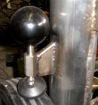
Een verdere uitbreiding van de <Aeio> robot, uitgevoerd in 2017 betreft
een eigen radar-sensor met controller voor gesture recognition. Hierdoor kan
<Aeio> ook volledig stand-alone werken in audio installatie projekten,
waarbij hij door beweging kan worden gestuurd. Hier een detail foto van Aeio,
met de gemonteerde radar sensor: 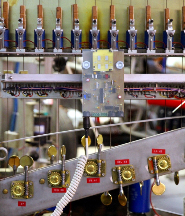 In deze volautomatische interaktieve modus speelt <Aeio> om beurten de
vijf komposities die in de firmware zijn ingebed.
In deze volautomatische interaktieve modus speelt <Aeio> om beurten de
vijf komposities die in de firmware zijn ingebed.
In het kader van de 50 ste verjaardag
van Logos, vertrok <Aeio> samen met vier andere robots van september 2018
tot april 2019 naar het Speelklok Museum in Utrecht. De specifieke omstandigheden
in die museale kontekst -een tentoonstelling rond muzikale robots- maakten een
nieuwe versie van radar-interface en embedded kompositie noodzakelijk. Voorzien
is nu ook in de mogelijkheid Aeio te stemmen zonder gebruik van een externe
computer.
De midi implementatie en de technische specifikatie voor deze
robot zijn opgenomen in de engelstalige beschrijving hierboven.
Geillustreerd bouwdagboek:
Omdat ons vaak wordt gevraagd hoeveel werk en tijd kruipt in,
en nodig is voor, het bouwen en ontwikkelen van een muzikale robot, hebben we
ook voor <Aeio> een beknopt bouwdagboek bijgehouden. Omdat we de bouw
tot in de laatste details graag illustreren, kan het ook voor anderen die ons
op dit pad willen volgen en/of verbeteren, van praktisch nut zijn. Bij onderhoud
en herstellingen aan deze robot, verdient het ook aanbeveling dit bouwdagboek
door te nemen.
- 22.02.2007: eerste ontwerptekeningen aan tafel en op papier. De experimenten
werden uitgevoerd naar aanleiding van de eerdere bouw van <Hurdy>.
Anders dan bij Hurdy willen we hier wel een echte klankkast voorzien. Daarvoor
kunnen we hetzij geexpandeerd isopropyl schuim gebruiken (massief blok) ofwel
een messing bovenblad gekoppeld aan een klassieke klankkast met een opening
berekend voor resonantie onder de frekwentie van de laagste open snaar. Een
klassieke houten klankkast met een bovenblad uit dennehout, zoals bij klavecimbels
en pianos ware ook denkbaar, esteties en uitvoerbaar geweest maar sloten we
uit gewoon vanwege onze voorkeur voor meer eigentijdse en stabiele materialen.
- 23.02.2007: inventarisering van de nodige E-kernen voor de elektromagneten.
Uittekenen principe schema voor de bipolaire elektromagnetische snaardrivers.
Opmeting bestaande instrumenten met midi noot 36: Kawai KG1 vleugel heeft
een snaarlengte van precies 1m voor die noot, op Hurdy hadden we 1m22 (snaar
gestemd op 33 maar kan ook tot 36 opgetrokken worden) , op mijn cello is het
71cm. Wanneer we alles besnaren met staal diameter 1.5mm dan is er geen enkel
risiko voor snaarbreuk. De spankracht per snaar wordt dan 250N (142N/mm2),
wat voor 12 snaren bij gelijke spanning komt op 3000N. De konstruktie van
het kader moet uiteraard navenant en met de nodige veiligheidmarges (we mikken
op 10kN) gedimensioneerd worden. De klankkast zou wat betreft binnenafmetingen
in teorie groter moeten zijn dan 130cm (1/4 golflengte bij 65Hz), wat moeilijk
te verwezenlijken is hier. Als alternatief kunnen we natuurlijk een vage Helmholtz
resonator toepassen of een golfpijp. Wat betreft materiaalkeuze voor het klankblad
zitten we meteen een stuk beter. Bij gebruik van hardmessing is een volle
golflengte bij 65Hz, 52 cm. Voor titaan (een materiaal dat we dolgraag zouden
gebruiken maar waar we niet aan weten te komen...) is het 79cm en voor duraluminium
84cm. Bij gebruik van dennehout, komen we uit op 61cm, in de vezelrichting.
- 24.02.2007: webpagina rond het <aeio> projekt (deze pagina...) presenteerbaar
gemaakt. Ontwikkeling van de nodige ontwerpberekeningssoftware voor de dimensionering
van deze automaat in Power Basic. Maatschets gemaakt.
- 25.02.2007: Twee inox U-dragers gelast voor de elektromagneten van de string
driver. Lastechniek met doorlopende tussenkoeling met behulp van de kompressor
toegepast ter beperking van de krimp. Breedte U-struktuur: 452mm. Aangelaste
zijstukken met 10mm brede sleuf: 60x100x4. De sleuf is nodig om de afstand
van de drivers tot de snaar te kunnen instellen. Ontwerp dempermechanisme
met Laukhuff magneten 24V. We monteren pianodempers op 4mm schroefdraden.

- 26.02.2007: Bestelling bij Farnell van een extra voorraadje lijnuitgangstransformatoren
en elektromagneten voor het uitvoeren van experimenten.
- 27.02.2007: Twee blikpakketten van de lijntransfos losgepeuterd en opnieuw
geassembleerd met uitsluitend behoud van de 33 E-kernplaatjes in mu-metaal.
Elektrische specifikaties opnieuw gemeten en uitgerekend na deze modifikatie
(cfr. tech specs. onderaan deze pagina).
- 28.02.2007: Levering Eagle 8W transfos van Farnell. Meteen twee stuks opengegooid
en op de slachtbank gelegd. Resultaten onderaan weergegeven. Voor verdere
experimenten ook besteld: vier stuks Stephenson Gobin Geofire type 58 magnets,
50 Newton, 5Watt, 12V. Type 2-58-0140-12DC. De verwachting is dat deze types
veel flux leveren bij DC en lage frekwenties, maar dat ze wellicht door de
grote wervelstroomverliezen niet zullen voldoen bij hoge frekwenties.
- 01.03.2007: levering Stephenson Gobin magneten. DC weerstand 33.6 Ohm, bij
20 graden Celsius. 41.2 Ohm bij 60 graden Celsius. Dit is de temperatuur die
bereikt wordt na 1 uur inschakeling op 12V dc. Demontage en herassemblage
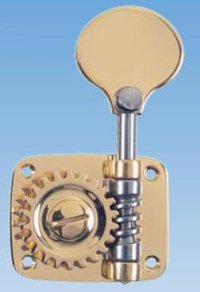
van alle 24 lijnuitgangstransfo-kernen afgewerkt. Kontrabas stemmechanieken
(12 stuks) besteld bij Geige24, Benjamin Fastner, in Duitsland. Kostprijs
259,28 Euro.
- 02.03.2007: Afmeten en snijwerk inox chassisdelen: draagplaat stemmechanismen
en vertikale kolommen. Voor de vertikale kolommen sneden we buis van 88.90mm
diameter, materiaaldikte 2mm, overlangs door met de plasma snijder. Lengte
van de langste kolom: 1442mm, van de kortste: 1022mm. Beide halve buizen moeten
worden vastgelast op stukken plat inox van 100x 8mm.
- 03.03.2007: Ganse dag TIG laswerk aan de vertikale kolommen. Ter vermijding
van elke krimp en doorbuiging van deze halfcirkelvormige kolommen dienden
we dit laswerk uit te voeren in zorgvuldig over de gehele lengte en alternerend
aan beide zijden van de werkstukken in segmentjes van 3 a 4 centimeter opgedeelde
stukjes, en dit met doorlopende tussenkoeling met perslucht. Vandaar dat de
5 meter lasnaad een gehele werkdag in beslag nam.

- 04.03.2007: Ontwerp snaarbevestiging bovenzijde. Selektie wielen: 400mm
diameter, asmaat 25mm. Bandbreedte 73mm. Uitsnijden trapeziodale dragers voor
elektromagneten en dempers in inox 8mm x 100 plaat. Voorschuren vertikale
kolommen. Boorwerk uitgevoerd met kobaltboren onder persluchtkoeling. Dit
geeft duidelijk zowel een langere standtijd van de boren als een beter boorrezultaat.
Uitsnijden 8mm dikke platen voor de stemsleutels. Alle inox AISI 304. Trapezoidale
dragers vastgelast op vertikale kolommen. Werktekeningen en lasplan opgesteld
op schaal 1:5.
- 05.03.2007: Wachten op inox levering van Demar Lux en op stemsleutel levering
uit Duitsland...
- 06.03.2007: Lasnaden ter evaluatie voorgelegd aan ATS.
- 08.03.2007: Stemsleutels geleverd. We waren er niet op bedacht maar hadden
het eigenlijk wel kunnen weten: een set stemsleutels voor een kontrabas bestaat
uit vier verschillende sleutels met verschillende maatvoering! Met onze drie
sets hebben we dus van elke sleutelmaat drie exemplaren...
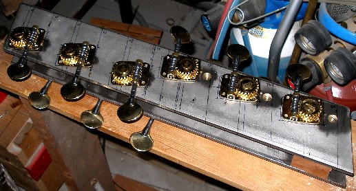
- 09.03.2007: Uittekenen en voorboren van de inox stukken voor de stemsleutelkast.
Grondplaat afmetingen van de sleutels: 60 x 40 mm. De snaarwalsen lopen taps
van 14.5mm tot 13mm. Pech bij de pogingen om draad te tappen in het inox voor
de bevestiging van de stemsleutels: M3 tap afgebroken in boorgat...
- 10.03.2007: Selektie elektromagneten voor de dempers: 24V types traktuurmagneten
van Laukhuff. We blijken ze zelfs nog op voorraad te hebben.
- 11.03.2007: Wielselektie:
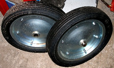 .
Deze wielen hebben 400mm diameter en worden links en recht van de kolommen
gemonteerd. We hadden ze nog op voorraad.
.
Deze wielen hebben 400mm diameter en worden links en recht van de kolommen
gemonteerd. We hadden ze nog op voorraad.
- 12.03.2007: De inox levering is niet te verwachten voor vrijdag 16.03...
De bovenste snaarhouderkonstruktie moet dus wat wachten.
- 13.03.2007: Zoeken naar een koppel geschikte zwenkwielen. Bespreking PIC
implementatie met Johannes Taelman.
- 14.03.2007: Prototype kode ontwikkeling met Johannes. dsPIC30F3010, microchip.
Hiervoor gebruiken we de MPLAB C-compiler.
- 15.03.2007: Begin tappen van 48 M3 schroefdraden in de stemsleutelplaten.
- 23.03.2007: Tappen lukt slechter dan gedacht in inox met M3.
- 24.03.2007: Uitwerken software voor de berekening van de spektrale inharmoniciteit
van snaren. De boventonen vormen bij <aeio> beslist geen platonische
reeks harmonieken! cfr. 1086.html en 4040.html
- 03.04.2007: Onderzoek naar ferrofluids voor een betere magnetische koppeling.
- 14.04.2007: Onderzoek naar magneetmaterialen: legeringen en gesinterde ferrieten.
- 02.10-05.11.2007: Verder experimenteel onderzoek op <Hurdy>, wat een
geschikt testplatform is voor Aeio.
- 06.11.2007: Bouw en verdere ontwikkeling voorgesteld aan Hogeschool Gent
als postdoktoraal onderzoeksprojekt.
- 07.11.2007: Verdere uitwerking van het onderzoeksvoorstel rond de bouw van
<Aeio>
- 08.11.2007: Werk aan het stemblok weer opgenomen. Voor de bevestigingsgaten
gaan we uiteindelijk toch over op M4 boutjes. De problemen met het afbreken
van de tappen bij gebruik van M3 in ons 10mm dikke materiaal blijken onoverkomelijk.
- 09.11-02.12.2007: Voorbereidend experimenteel werk op het Hurdy platform
voor evaluatie van de elektromagnetische besturing van de snaren.
- 04.12.2007: Eerste voorlopige montage van het gehele stemblok.
- 29.12.2007-20.01.2008: Research in verband met materialen voor het klankbord.
Polystyreen zou ideaal zijn maar vanwege de gebrekkige duurzaamheid toch te
verwerpen. In eerste instantie zullen we het dus maar op hard messing houden.
- 21.01.2008-14.02.2008: Verder ontwikkelingwerk aan de generatorkode voor
de PIC processoren.
- 15.02-15.04.2008: Verdere proeven op het Hurdy platform i.v.m. het strijkmechanisme
- 28-29.05.2008: Assemblage stemschroeven op schotelveren. Het stemblok krijgt
een licht konisch verloop. Alle stemmechanismen vastgezet met M4 inox boutjes.
- 31.05.2008: Zijstukken uitgezaagd (hoge kant: plat 30.0 x 3.0 x 105.5, lage
kant: plat 35.0 x 3.0 x 105.5) en ingelast met een volle doorgelaste naad
om later resonanties te voorkomen. Koeling met perslucht ter vermijding van
kromtrekken. Maatplan:
- 01.06.2008: Ontwerp snaarhouder bovenzijde. Te konstrueren uit inox plat
100.0 x 10.0 x 700.0. Uittekenen grondplan voor wielbazis.:
- 02.06.2008: Afdraaien assen met sleuf voor omega ring of circlip. Aanlassen
assen (135mm lang) op inox plat 50.0 x 10.0 x 300.0. Uitwerking tekening hoogteligging
wielen en wielbazis.
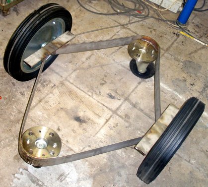
- We beslisten uiteindelijk toch een vier-wieler te ontwerpen, maar dan met
de wielen in een ruitstand, waardoor een extreem grote beweeglijkheid kan
verkregen worden. Terplaatste ronddraaien is perfekt mogelijk. Voor de grote
wielen pasten we geen doorlopende as toe omwille van de noodzakelijke toegankelijkheid,
ook aan de onderzijde, van het stemblok. De assen werden gedraaid uit inox
(niet gehard).
- 03.06.2008: Uittekening plan voor de uitlijning van de snaren en de boring
van de snaarhouder aan de bovenkant. Eerste precieze bepaling van de liggingen
van de kammen. De doorvoergaten voor de snaren kunnen vanwege de schuinstand
niet geboord worden maar moeten worden uitgefreesd met een vingerfrees.
- 04.06.2008: Boren en tappen draad in inox flenzen voor de bevestiging van
de zwenkwielen. Draad: M10. Verder plooiwerk voor de horizontale chassisdragers
(60.0 x 4.0, inox plat). Stukken aangelast op de vlakke lasflenzen (NW40,
DIN2576 ND10). Plooihoeken op 60 graden gebracht. Lastafel klaargemaakt voor
de eindmontage van het gehele onderchassis met de wielen. Onderchassis gelast
en op maatvoering getest.
- 05.06.2008: Uittekenen en narekenen klankkastkonstruktie. Konstruktie dragerchassis
voor de dempers. Aftekenen snaarvoering op de onderdelen van het chassis.

- 06.06.2008: Uitwerking bovenste snaarhouder: uitslijpen boorvlakjes voor
het boren van de schuine gaten (gatmaat 3.1mm) voor de doorvoer van de snaren.
We dienden dit wel zo op te lossen, aangezien we niet over een freesmachine
beschikken in onze werkplaats. Zagen 50.1mm buisjes -6 stuks- voor de snaargeleiding.
Hierin kunnen lampjes (LED-spotjes) worden geplaatst. Deze buisjes worden
vastgelast op de bovenplaat. Snijden en afmeten houdprofielen voor het messing
klankbord. Hierin moeten de boutgaatjes (M4) geboord worden vooraleer de profielen
worden vastgelast op het chassis. Voor het boven en onderprofiel passen we
inox L-profiel toe van 20.0 x 20.0 x 3.0. Het tegenspanprofiel is dan plat
15.0 x 3.0. Boutjes: inbus hex, M4 x 10.
- 07.06.2008: Konstruktie en uitboren profielen voor de bevestiging van het
messing klankbord. Boven- en onderprofiel vastgelast. Voor de zijprofielen
gebruiken we inox 20 x 20 x 3, maar daarvan zagen we een smalle strook af.
Het tegenspanprofiel wordt hier 10.0 x 2.0, zoniet zou er te weinig trilruimte
overblijven voor de kam van de laagste en de hoogste snaar. Boorafstand gaten
<= 30mm.
- 08.06.2008: Alle bevestigingsprofielen voor het messing klankblad geboord
en vastgelast. In totaal wordt het klankbord vastgezet met 98 stuks M4 x 12
inox inbus boutjes. Eerste uitsnijding van het klankblad zelf in hard messing
(MS 58, F51, graveerkwaliteit). Levermaat: 2000 x 600 x 0.8. Treksterkte >
490 N/mm2, rekgrens delta 5% = 9, Brinell hardheid 150) (MS50 = CuZn39Pb3,
werkstof nr. 2.0401, ASTM 360, AFNOR UZ39PB2). Ook bij voorlopige montage
blijkt de klank heel behoorlijk te zijn. De resonantiefrekwentie ligt -zoals
berekend- inderdaad beneden de frekwentie van de laagste open snaar. Veelbelovend
dus...
- 09.06.2008: Tweede ontwerp schakelingen: Hierbij gingen we uit van een master-controller
die de arbitrage verzorgt van de door de gebruiker gevraagde toon in funktie
van de (nog) beschikbare snaren bij polyfoon gebruik. In dit opzet is het
essentieel dat ook de dempers vanuit deze master-controller worden bestuurd.
De noten zijn immers niet vast toegewezen aan bepaalde snaren.
 De master
kontroller kommuniceert met de twaalf individuele PIC kontrollers via seriele
datalijnen. In dit schema werd meteen ook een optie voorzien voor een exciter
magneet, dit om eventueel de attack van de tonen te kunnen versnellen. Die
mogelijkheid moet echter nog verder worden onderzocht. Aan ingangszijde werd
zowel een klassieke midi-input voorzien als een UDP/IP netwerkaansluiting.
De midi uitgang levert wanneer netwerk besturing gebruikt wordt, alle niet
voor Aeio bestemde informatie als standaard midi door. Bij uitwerking van
de schakelingen volgens dit opzet wordt het schakelschema voor de snaardrivers:
De master
kontroller kommuniceert met de twaalf individuele PIC kontrollers via seriele
datalijnen. In dit schema werd meteen ook een optie voorzien voor een exciter
magneet, dit om eventueel de attack van de tonen te kunnen versnellen. Die
mogelijkheid moet echter nog verder worden onderzocht. Aan ingangszijde werd
zowel een klassieke midi-input voorzien als een UDP/IP netwerkaansluiting.
De midi uitgang levert wanneer netwerk besturing gebruikt wordt, alle niet
voor Aeio bestemde informatie als standaard midi door. Bij uitwerking van
de schakelingen volgens dit opzet wordt het schakelschema voor de snaardrivers: Van deze schakeling hebben we dan twaalf exemplaren nodig.
- 10.06.2008: Lassen en monteren draagsteun voor de dempers. De juiste hoogteligging
in het chassis moet nog worden bepaald en de gaten zijwaarts uitgeboord.
 De hier gebruikte elektromagneten (August Laukhuff types) werken op 24V. Hier
passen we geen pulssturing met overspanning toe want de dempers moeten met
100% duty cycle kunnen werken. De dempers zelf, met dik pianovilt, moeten
nog gebouwd en ontworpen worden. We kunnen daarbij uitgaan van de dempers
zoals we die bouwden voor de <Hurdy> robot. De voeding voor deze komponent
moet gedimensioneerd worden voor 24V/ 3.5A. (ca. 84W)
De hier gebruikte elektromagneten (August Laukhuff types) werken op 24V. Hier
passen we geen pulssturing met overspanning toe want de dempers moeten met
100% duty cycle kunnen werken. De dempers zelf, met dik pianovilt, moeten
nog gebouwd en ontworpen worden. We kunnen daarbij uitgaan van de dempers
zoals we die bouwden voor de <Hurdy> robot. De voeding voor deze komponent
moet gedimensioneerd worden voor 24V/ 3.5A. (ca. 84W)
- 11.06.2008: Definitieve montage van het klankbord in het chassis. Uitmeten
van de resonantie-eigenschappen. De laagste frekwentie blijkt rond de 10Hz
te liggen, een uitstekend resultaat. Uiteraard zullen deze eigenschappen zich
nog in grote mate wijzigen wanneer de kam of de kammen op het klankbord wordt/worden
geplaatst.
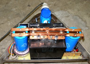
- 12.06.2008: Ontwerp voeding voor de snaardrivers. Hier willen we zeker geen
switcher toepassen hoewel dit gezien de enorme stromen voor de hand lijkt
te liggen. Maar voor de hier nodige vermogens hebben switchers steeds ventilatoren
(lawaai!) en veroorzaken ze heel wat storingen en harmonischen. Vandaar ons
ontwerp van een welhaast prehistorische voeding waarin voor de spanningsregulering
een verzadigende transformator in de primaire kring wordt gebruikt. Wanneer
de opgenomen stroom toeneemt, neemt ook de stroom door de regelwikkeling toe
(ze is immers in serie geschakeld) , waardoor er een grotere stroom door deze
transfo gaat lopen en de kern meer verzadigd raakt en dus de zelfinduktie
-en daarmee de impedantie- afneemt. De spanningsval over de primair in serie
geschakelde wikkeling moet in onbelaste toestand 55V bedragen. De DC weerstand
van deze wikkeling moet zo klein mogelijk zijn.
 Dit is het
soort spanningsregeling zoals we die aantroffen in een lot oude 48V voedingen
uit telefooncentrales daterend van voor de tweede wereldoorlog. De regeling
is uiteraard niet verliesvrij, maar bevat geen echt 'aktieve' komponenten
in de regelkring. Een alternatief ontwerp zou kunnen gebruik maken van een
eenvoudige smoorspoel met een verzadigende kern in serie met de primaire wikkeling.
Dit moeten we nog uittesten. De dikke diodes worden gemonteerd op rood koperen
strips die tevens ook de grote elkos dragen en als koelvin fungeren. De voeding
voor de mikrokontrollers en de TTL logika chips is rechtoe rechtaan evenals
die voor de dempers. Voor deze laatste is stabilisatie zelfs geen vereiste.
Dit is het
soort spanningsregeling zoals we die aantroffen in een lot oude 48V voedingen
uit telefooncentrales daterend van voor de tweede wereldoorlog. De regeling
is uiteraard niet verliesvrij, maar bevat geen echt 'aktieve' komponenten
in de regelkring. Een alternatief ontwerp zou kunnen gebruik maken van een
eenvoudige smoorspoel met een verzadigende kern in serie met de primaire wikkeling.
Dit moeten we nog uittesten. De dikke diodes worden gemonteerd op rood koperen
strips die tevens ook de grote elkos dragen en als koelvin fungeren. De voeding
voor de mikrokontrollers en de TTL logika chips is rechtoe rechtaan evenals
die voor de dempers. Voor deze laatste is stabilisatie zelfs geen vereiste.
- 13.06.2008: Werkvergadering met Johannes Taelman m.b.t. de mikroprocessor
architektuur en de te gebruiken protokollen. Bespreking van het printboard
ontwerp voor de ds-PIC schakeling.
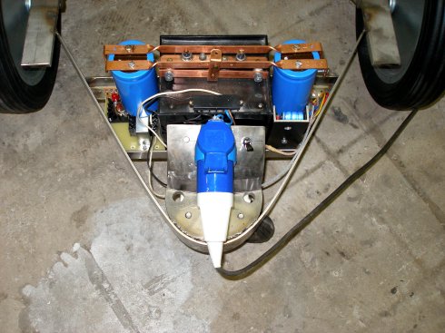
- 14.06.2008: Inbouw van de geteste voedingsmodules in het chassis van de
automaat. Ontwerp netvoedingsaansluiting en schakelaar. Voor de net- aansluiting
wordt een blauwe mannelijke CEE stekker (opbouwtype, 16A) gebruikt. Schakelaar
en aansluitdoos zijn gemonteerd op een vierkantig bolsegment in Inox AISI316
waarop een vlak stuk aan de onderzijde is gelast waardoorheen een M12 inox
bout komt die het stroomvoorzieningsgedeelte vastzet op de achterste wielflens.
Voor onderhoud en herstelling (bvb. van de schakelaar die we kwa duurzaamheid
toch niet erg vertrouwen...) volstaat het dus om die ene bout los te maken.
De netaarde is via een M4 boutje met dit chassisdeel verbonden. Wanneer om
een of andere reden een groundlift nodig is, volstaat het deze ene verbinding
los te maken. <Aeio> zelf veroorzaakt geen lekstromen, gezien hier geen
schakelende voedingen zijn toegepast.
- 15.08.2008: Overweging en studie van de mogelijkheid om OSC toe te passen
via UDP/IP. Voor de konstruktie van de stuurstang moeten we inox stafmateriaal
met een diameter van 18mm bestellen. Dit past precies in de gaten van de achterflens.
Uitvoerige test met wisselende belastingen van het gehele voedingsblok.
- 16.08.2008: De voeding heeft de 24u test doorstaan.
 Op de foto zien we het onderstel met integraal voedingsblok. De opstand met
het eigenlijke instrument is er nog niet opgelast.
Op de foto zien we het onderstel met integraal voedingsblok. De opstand met
het eigenlijke instrument is er nog niet opgelast.
- 21.06.2008: Afmeten en boren van de pasgaten voor de demperassemblage op
de aangelaste zijstukken. Het demperblok komt met de basisplaat 50mm boven
het elektromagnetisch strijkmechanisme te zitten. Uiteraard moet het daarmee
heel precies evenwijdig lopen.
- 22.06.2008: Konstruktie van de geplooide onderkam. Plooimal schaal 1:1 gemaakt.
Deze kam wordt vervaardigd uit inox plat 25.0 x 3.0, de kant naar de snaar
wordt daarbij heel precies afgerond en geslepen. De zijkanten worden vastgelast
op het hoofdchassis. De optie om extra resonatoren op deze kam aan te brengen
blijft open. In dat geval zouden we opteren voor konische resonatoren een
beetje zoals die toegepast in de instrumenten van de gebroeders Baschet.
- 23.06.2008: Proeven met materialen en opstelwijzen voor de bovenkam. Metaal
blijkt hier geen goede keuze. De inox kam die we uitprobeerden klinkt verschrikkelijk...
Eikenhouten lat, dikte 6mm, hoogte 30mm klinkt aanvaardbaar maar dempt toch
iets teveel. Bij wijze van experiment enkele individuele kammen gemaakt in
teakhout, gelijkzijdig en afgeschuind. Dit klinkt heel wat beter en laat individuele
afregeling van de snaren toe. De vezelrichting van het hout blijkt geen hoorbaar
verschil op te leveren. In teorie zou kops hout nochtans het beste moeten
zijn. Alle snaren bij wijze van eerste proef opgelegd. De randsnaren (36 en
47) blijken toch wat problemen te hebben met resonantie.
 De ronde uitholling in de kammen (gat diameter 12mm) maakt de klank een ietsje
briljanter. Voor de randsnaren kunnen we verder experimenteren met kammen
met ronde voet, ofwel met een gemeenschappelijke kam voor de beide uiterste
snaren, waardoor de trilling van de uitersten beter wordt overgedragen op
een verder van de rand gelegen deel van het klankblad. Overigens: de hoogte
van elke kam moet afzonderlijk worden bepaald vanwege de (geringe) doorbuiging
van het klankblad naar het midden toe.
De ronde uitholling in de kammen (gat diameter 12mm) maakt de klank een ietsje
briljanter. Voor de randsnaren kunnen we verder experimenteren met kammen
met ronde voet, ofwel met een gemeenschappelijke kam voor de beide uiterste
snaren, waardoor de trilling van de uitersten beter wordt overgedragen op
een verder van de rand gelegen deel van het klankblad. Overigens: de hoogte
van elke kam moet afzonderlijk worden bepaald vanwege de (geringe) doorbuiging
van het klankblad naar het midden toe.
- 24.06.2008: Ontwerp experimentele zijkammen:
 Berekeningssoftware
voor het <Aeio> projekt aangepast en verder uitgewerkt naar inharmoniciteit
toe. De berekende lookups zijn te zien in aeio.txt.
Eerste prototype voor de dempers gebouwd. Het vilt zal zeker 10mm dik moeten
zijn voor een behoorlijke demping.
Berekeningssoftware
voor het <Aeio> projekt aangepast en verder uitgewerkt naar inharmoniciteit
toe. De berekende lookups zijn te zien in aeio.txt.
Eerste prototype voor de dempers gebouwd. Het vilt zal zeker 10mm dik moeten
zijn voor een behoorlijke demping.
- 25.06.2008: Experimenten met ander snaarmateriaal: basgitaarsnaren, met
nikkel omwikkeling. Deze snaren hebben een geringere inharmoniciteit, maar
de geluidsproduktie is ook aanzienlijk geringer.
- 29.06.2008: Uitlijnen elektromagnetische drivers in hun dragers. Selektie
van geschikt 'potting' materiaal. Voor de positionering in de U-dragers is
Parabond 600 heel geschikt.
- 30.06.2008: Ontwerp kontrakt onderzoeksprojekt opgesteld voor Hogeschool
Gent. Het hele dossier overgemaakt aan de departementssekretaris, Stijn Seghers.
- 05.07.2008: Houtsnijwerk voor de 12 dempers. We sneden deze uit teak hout.
De M5 schroefdraden op de bouten moeten verder worden getrokken. De bouten
zelf (inbus types) komen verzonken in het hout te zitten. Als fixatie gebruiken
we hierbij cyaanacrylaat lijm.
 .
De viltstrippen worden vastgelijmd op het teak hout met MS-polymeer.
.
De viltstrippen worden vastgelijmd op het teak hout met MS-polymeer. 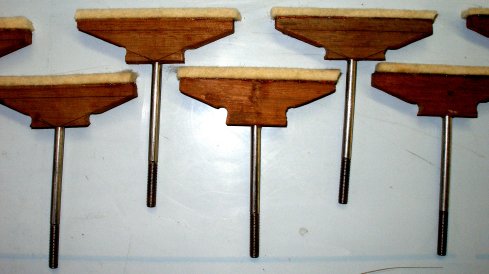
- 06.07.2008: 30mm extra M5 draad getapt op de bouten van de dempers. Eerste
proefmontage met alle dempers. Konstruktie geleidingskammetjes om de uiterste
snaar iets meer naar het centrum te verplaatsen.
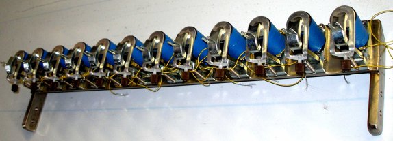
 De
aandachtige lezer zal zien op de foto dat er 13 dempers op staan afgebeeld:
we maakten nog heel wat meer dempers... in reserve voor herstellingen, ongelukjes
en 'spare parts'.
De
aandachtige lezer zal zien op de foto dat er 13 dempers op staan afgebeeld:
we maakten nog heel wat meer dempers... in reserve voor herstellingen, ongelukjes
en 'spare parts'.
- 07.07.2008: e-snaar driver houders terug losgemaakt. Studie van het bedradingsprobleem.
Ontwerp boorplan voor de bedradingsgaten.
 Schema voor de bedrading van de drivers opgebouwd met de Eagle transformatoren
uitgetekend. De getekende terugslagdiodes zouden we liever helemaal weglaten
of vervangen door kleine kondensatoren, indien toelaatbaar voor de mosfets.
De klank is gewoonweg een heel stuk beter. Ombouw twee extra Eagle transformatoren.
Eerste montage van de drivers in het frontale chassis met Parabond 600. De
twaalf doorvoergaten voor de draden zijn geboord op 5.5mm. De drie montagegaten
voor het L profiel met de verbindingen zijn 4mm.
Schema voor de bedrading van de drivers opgebouwd met de Eagle transformatoren
uitgetekend. De getekende terugslagdiodes zouden we liever helemaal weglaten
of vervangen door kleine kondensatoren, indien toelaatbaar voor de mosfets.
De klank is gewoonweg een heel stuk beter. Ombouw twee extra Eagle transformatoren.
Eerste montage van de drivers in het frontale chassis met Parabond 600. De
twaalf doorvoergaten voor de draden zijn geboord op 5.5mm. De drie montagegaten
voor het L profiel met de verbindingen zijn 4mm. 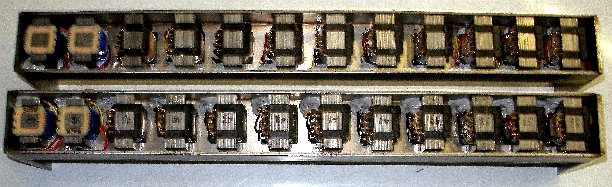 Op de foto zien we de reeds geassembleerde omgebouwde snaardrivers. Dit zijn
de beide kanten die naar de snaren toe zullen staan. De uiteindelijke montage
ziet er dan uit als:
Op de foto zien we de reeds geassembleerde omgebouwde snaardrivers. Dit zijn
de beide kanten die naar de snaren toe zullen staan. De uiteindelijke montage
ziet er dan uit als: 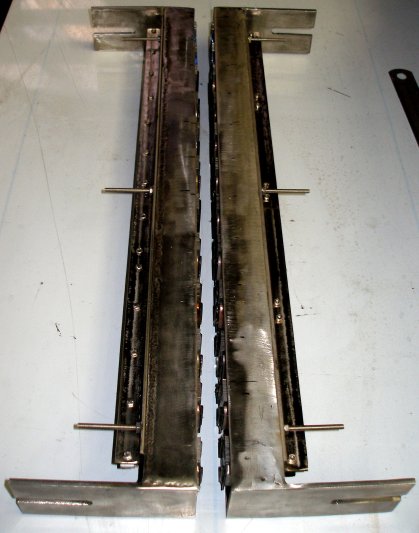
- 08.07.2008:Uittekenen detail schema voor de Philips transformator drivers.
 Montage
van de achterste e-drive transformatoren in spiegelbeeld met die van de voorzijde.
Elke driver wordt met vier draden buiten het chassis gebracht. De Eagle drivers
(4 stuks in totaal) worden op een plaatje aluminium van 5mm dikte gemonteerd
omdat ze precies 5mm minder hoog zijn. Op deze wijze is de snaar-magneet afstand
voor alle drivers identisch. Na de elektrische tests is het de bedoeling de
integrale snaardriver in te gieten met een potting-compound. waardoor ook
een betere warmte-afvoer mogelijk moet worden.
Montage
van de achterste e-drive transformatoren in spiegelbeeld met die van de voorzijde.
Elke driver wordt met vier draden buiten het chassis gebracht. De Eagle drivers
(4 stuks in totaal) worden op een plaatje aluminium van 5mm dikte gemonteerd
omdat ze precies 5mm minder hoog zijn. Op deze wijze is de snaar-magneet afstand
voor alle drivers identisch. Na de elektrische tests is het de bedoeling de
integrale snaardriver in te gieten met een potting-compound. waardoor ook
een betere warmte-afvoer mogelijk moet worden.
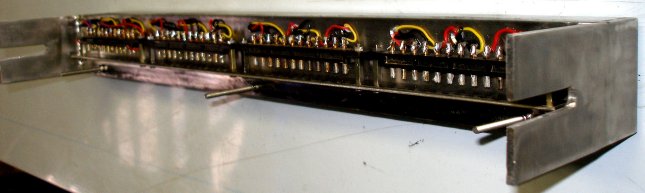
- 09.08.2008: Konstruktie soldeeraansluitstrips en dito dragers op de e-drivers.
 Op deze foto zien
we de bedrading van de achterste snaardriver. De draden werden hier aan op
een strook dik teflon gemonteerde soldeerlipjes gesoldeerd. Voor de voorkant
gebruikten we prachtige, oerdegelijke maar van voor 1940 daterende draadsteunen:
Op deze foto zien
we de bedrading van de achterste snaardriver. De draden werden hier aan op
een strook dik teflon gemonteerde soldeerlipjes gesoldeerd. Voor de voorkant
gebruikten we prachtige, oerdegelijke maar van voor 1940 daterende draadsteunen:
 . Daarvan hadden
we niet genoeg voorraad om ook de achterzijde daarmee uit te voeren. Detail
van de draadsteuntjes:
. Daarvan hadden
we niet genoeg voorraad om ook de achterzijde daarmee uit te voeren. Detail
van de draadsteuntjes: 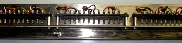 De lange uitstekende draadeinden (M4 inox draad) zijn bedoeld voor het later
aanbrengen van doorzichtige polykarbonaat afschermingen.
De lange uitstekende draadeinden (M4 inox draad) zijn bedoeld voor het later
aanbrengen van doorzichtige polykarbonaat afschermingen.
- 10.07.2008: Precizie slijpwerk om de e-bow mechanismen perfekt glijdend
op het hoofdchassis te kunnen monteren. Ook de afregelsleuven moeten heel
precies bijgevijld en geslepen worden (breedte: 10mm). Elektrische nameting
van de gemonteerde elektromagneten.
- 11.07.2008: Eerste tests en metingen met frekwentiesturing van het mechanisme.
Hiervoor gebruiken we een precieze toongenerator aangesloten op een Klein
& Hummel meetversterker (140W sinus vermogen). Wanneer we 45V (40Hz, voor
Mib) aansluiten op de 100V wikkeling van de drivers trilt de snaar op de verwachte
frekwentie van 80Hz (Mib). De in de 8 Ohm wikkeling geinduceerde spanning
is dan 830mV. De induktief opgewekte onbelaste spanning in de tegenovergeplaatste
driver (gemeten over de 100V wikkeling) is 2.54V. De koppelfaktor tussen beide
elektromagneten is dus ca. 5%. Uiteraard hangt dit nogal af van de afstand
tussen beide spoelen. Bij deze eerste proeven bedroeg deze afstand ca. 12mm.
Een aansturing met een zuivere sinus levert het beste rezultaat. Het timbre
van de snaarklank blijkt in hoge mate afhankelijk van de amplitude van de
aansturing, een beoogd en voorzien rezultaat overigens.
- 12.07.2008: Aeio van de lastafel afgetakeld -de konstruktie is te zwaar
om nog met individuele mankracht opgeheven te kunnen worden- en op het wielstel
gemonteerd. Rechtstandig vastlassen op onderstel.
- 13.07.2008: Overweging om 12 kontrollers te implementeren waarmee de feitelijke
stemming van de snaren (default is en blijft 36-47) zou kunnen gewijzigd worden.
Hiervoor komen de kontrollers 24-35 in aanmerking. Bij omstemming van de snaren,
wordt aeio dan natuurlijk een transponerend instrument. Spijtig is ook hier
weer dat midi niet toelaat die ook mikrotonaal te doen. Mikrotonale basisstemmingen
vergen immers alweer een extra reeks van 12 kontrollers waarmee de toonhoogte
ook in cents kan worden ingesteld. Kontrollers 24-35 rezerveren we in elk
geval alvast voor deze optie.
- 14.07.2008: Eerste voorontwerp montage PC boards op het chassis. Het wachten
is evenwel op de PC boards voor de drivers...
- 15.07.2008: Ontwerp en uitvoering vastzetters (remmen) voor de beide grote
wielen.
 Hiervoor
gebruiken we stelvoeten met rubbervlak op een kogelgewricht in een inox M12
uitvoering. De bediening gebeurt via een grote bakelieten kogelkop of een
sterknop. Omwille van de instelbaarheid monteerden we in de schroefdraad van
de kogels (die is 28mm diep) een stuk M12 tige -lengte 13mm- voorzien van
een zaaggleuf. Om de stelvoeten te verwijderen moet het wiel worden weggenomen.
Hiervoor
gebruiken we stelvoeten met rubbervlak op een kogelgewricht in een inox M12
uitvoering. De bediening gebeurt via een grote bakelieten kogelkop of een
sterknop. Omwille van de instelbaarheid monteerden we in de schroefdraad van
de kogels (die is 28mm diep) een stuk M12 tige -lengte 13mm- voorzien van
een zaaggleuf. Om de stelvoeten te verwijderen moet het wiel worden weggenomen.
- 16.07.2008: Ontwerp van hamertjes die als autonome speelelementen bruikbaar
kunnen zijn, maar kunnen meehelpen om de aanspreeksnelheid van de snaren wat
te versnellen. Experimenten met vilt-beklede pianohamertjes en met leder beklede
exemplaren. De midi-mapping van deze hamertjes leggen we best in het oktaaf
onder de normale tessituur van het instrument.
- 17.07.2008: Plasma snijwerk van de drager voor de kloppertjes. Dit stuk
volgt de kurvatuur van de aanslagpunten op de snaar. Als vertrekpunt namen
we hiervoor 1/9 van de snaarlengte. Deze drager wordt met 4 boutjes op het
hoofdchassis geschroefd. Daartoe lasten we twee stukjes onder verstek uitgezaagd
hoekprofiel 20x20x3 op de vertikale dragers.
- 18.07.2008: Eerste proefmontage hamertjes. Aftekenen boorgaten in bevestigingsprofiel.
Konstruktie van de hamertjes met elektromagneten, hechting met Parabond 600
en twee houtschroefjes. Polieren drager na uitboren van alle bevestigingsgaten.
We hebben in onze voorraad twee magneten tekort. Bijbesteld bij Laukhuff.

- 19.07.2008:
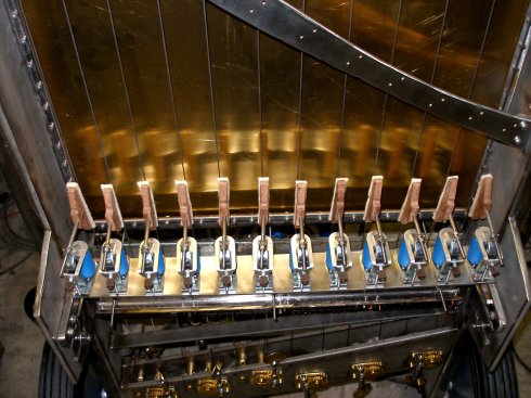 Op de foto zien we de voorlopig gemonteerde dempers evenals, bovenaan, een
stuk van het draagprofiel voor de hamers. Opnieuw montage van de hamers zelf,
na uitharding van de Parabond kit. Afregeling van het bewegingstrajekt en
het aanslagpunt van de -voorlopig slechts tien- voorhanden en afgewerkte hamers.
De repetiesnelheid van deze hamers is relatief laag: maximaal ca. 4 aanslagen
per sekonde. Het resonantiepunt moet nog bepaald worden.
Op de foto zien we de voorlopig gemonteerde dempers evenals, bovenaan, een
stuk van het draagprofiel voor de hamers. Opnieuw montage van de hamers zelf,
na uitharding van de Parabond kit. Afregeling van het bewegingstrajekt en
het aanslagpunt van de -voorlopig slechts tien- voorhanden en afgewerkte hamers.
De repetiesnelheid van deze hamers is relatief laag: maximaal ca. 4 aanslagen
per sekonde. Het resonantiepunt moet nog bepaald worden.
- 20.07.2008: Studie van de kabel geleidingen, voorkant en achterkant. Buisvoering
al dan niet in kombinatie met spirawrap.In totaal hebben we 108 geleiders
nodig, 30 aan de achterkant, 78 aan de voorkant.
- 21.07.2008: Voorbereiding atelierruimte voor de elektronische werkzaamheden
aan Aeio. Opruimsessie.
- 22.07.2008: Ontbrekende elektromagneten, besteld bij Laukhuff, geleverd.
Afwerking van de twee ontbrekende hamertjes.
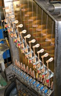
 De gemonteerde
maar nog niet bedrade hamertjes zijn te zien op de werkfotos. Het spijtige
aan het huidige uitzicht is wel dat het instrument nu eerder riskeert geassocieerd
te worden met de klasse der pianos, terwijl het toch eigenlijk in wezen een
strijkinstrument is en blijft. Da's natuurlijk voer voor diskussie onder de
organologen...
De gemonteerde
maar nog niet bedrade hamertjes zijn te zien op de werkfotos. Het spijtige
aan het huidige uitzicht is wel dat het instrument nu eerder riskeert geassocieerd
te worden met de klasse der pianos, terwijl het toch eigenlijk in wezen een
strijkinstrument is en blijft. Da's natuurlijk voer voor diskussie onder de
organologen...
- 23.07.2008: Johannes' eerste printontwerp voor onze hardware (de dsPIC boards)
is klaar. ... Begin van de bedradingswerkzaamheden. Kabelbomen voor de dempers
en de harnertjes afgewerkt.
- 24.07.2008: Nog wat printontwerp wijzigingen aangebracht. We wachten nu
op de produktie. Het Aeio projekt toegelicht op de open deur dag bij Logos.
- 25.07.2008: Bestelling bij Farnell van de nodige elektronische komponenten
en chips: ICL7667 MOSFET drivers, dsPIC30F3010/SP, MOSFET koelvinnen, #1213436
bestelnummer. Ontwerp draagstruktuur voor de 12 PC boards met de dsPIC processors.
- 28.07.2008: Printjes besteld bij Eurocircuits. Dit duurt 7 werkdagen. De
boardmaten zijn 119mm x 53mm.
- 05.08.2008: Printjes voor <Aeio> geleverd door Eurocircuits. Begin
van de bestukking... We vallen evenwel zonder IRL640 MOSFETS, dus meteen bijbesteld
bij Farnell. Eerste proefexemplaar opgebouwd met vier IRLZ44 Mosfet's en SF52
clamp-diodes over de BUZ345 Mosfets.
- 06.08.2008: Soldeerwerk printjes. Uittekenen eerste bedradingsplan. Weidmueller
konnektors, 15MHz kristallen, 10k weerstanden, rode 3mm LED's hebben we extra
moeten bestellen. Onze voorraad bleek toch te klein...
- 07.08.2008: Eerste onderdelenlevering Farnell. We kunnen nog een heel eind
verder solderen.
- 08.08.2008: Proefopstelling PC boards en ontwerp koperen voedingsrails.
- 09.08.2008: Prototype van een geheel bestukte print meegegeven met Johannes
Taelman voor kode ontwikkeling.
- 11.08.2008: Levering Farnell. We kunnen weer wat boardjes verder bestukken.
Nieuw geheel bestukt prototype klaargemaakt voor paswerk ontwerp chassis.
Voor het overige blijken we toch weer onze voorraden aan onderdelen overschat
te hebben. Nu vallen we zonder Weidmueller chassisdelen, 7810 regulators,
2.54 pin headers en... alweer IRL640 mosfets.
- 12.08.2008: Montage van de koelvinnen en de BUZ345 power mosfets op alle
PC boards.
- 14.08.2008: Ontwerp 15V voeding voor de mosfet drivers.
- 16.08.2008: Start uitwerking konstruktie print dragers. Insolderen tantaalkondensatoren
en buffer elkos op de printjes.
- 17.08.2008: De BUZ345 mosfets blijken niet meer in produktie te zijn. Bij
Farnell zijn ze niet meer leverbaar en er is ook geen echt vervangtype...
Mogelijke vervangers in dit ontwerp (in TO220 behuizing dan wel...) zijn IRF540,
IRF1310NPBF, ...
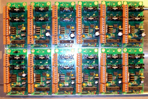 Op de foto zijn alle twaalf bestukte printjes te zien.
- 21.08.2008: Uitzagen van de basismontageplaat voor de twaalf PC-boards van
de snaardrivers. Aanlassen onder verstek uitgezaagde en op voorhand uitgeboorde
montagehoekjes op chassis. De gehele plaat met de PC boards kan worden losgenomen
achteraf. Ze wordt bevestigd met vier M6 x 10 inox inbus boutjes. Aftekenen
van de nodige montagegaten en boren ervan. De rood koperen massageleiders
komen aan de onderzijde van de basisplaat te zitten. De montage van de boards
erop moet gebeuren met messing cilindertjes die zowel als afstandsbus dan
als massageleider dienst doen. Hiervoor moeten messing boutjes M4 worden gebruikt.
De koperen geleider voor de positieve voedingsspanning komt aan de bovenzijde
van de boards te zitten.
- 22.08.2008: Bedradingsplan van de printen uitgewerkt:
 Montage printjes op basisplaat. Montage 15V voeding (analoog) voor de mosfet
drivers eveneens op de basisplaat.
Montage printjes op basisplaat. Montage 15V voeding (analoog) voor de mosfet
drivers eveneens op de basisplaat. 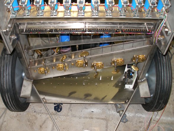
- 23.08.2008: Bestelling M4 FF en MF afstandsbussen voor de printmontage.
Levering zal pas voor 25.08 zijn. Farnell is traag geworden... Begin bedrading.
- 25.08.2008: Levering bestelde afstandsbussen. Montage van de printjes op
de basisplaat en montage van de koperen voedingsrails aan de printjes. Wanneer
om een of andere reden een print later moet worden losgenomen, moet altijd
eerste de positieve spanningsrail voor de gehele rij van zes printjes verwijderd
worden. Anders is immers de bout waarmee de print vastzit aan de massa-rail
niet bereikbaar.
- 26.08.2008: Bedrading +15V power lijnen voor de mosfet drivers. Bedrading
+5V voedingslijnen.
- 27.08.2008: Bedrading van de dempers en de hamertjes naar de besturingsboards.
De dikkere draden lopen naar de dempers, de dunnere naar de hamers. De kleurkodering
volgt grotendeels de kleurkode voor weerstanden, behalve 2= roze of rood/wit
(de rode draad is hier de 24V positieve voedingsgeleider) en 10=wit /zwart.
- 28.08.2008: Bedrading van de dubbele elektromagnetische snaardrivers. De
24 roze draden komen aan de gemeenschappelijke positieve voedingsspanning
via de Weidmueller konnektoren op de PC-boards. De gehele bedrading van alle
muzikaal relevante komponenten, op de UDP/IP en midihub processor na, is nu
afgewerkt en klaar voor een eerste firmware versie ter evaluatie.
- 29.08.2008: Eerste voorstudie van de lampjes en lichteffekten voorzien in
Aeio. Bestukken midihub board voor de eerste tests.
- 30.08.2008: Bespreking aeio firmware met Johannes Taelman.
- 31.08.2008: Hub board voorbereid. Wachten op firmware voor de stringdrivers.
- 03.09.2008: Aeio projekt voorgesteld op de demonstraties voor ISSSM.
- 04.09.2008: Mechanisch werk aan de dempers.
- 05.09.2008: Tests met verschillende dikten vilt.
- 13.09.2008: Ontwerp van een hardware midi-kanaal demultiplexer. Deze wordt
voorzien van 1 midi ingang en 16 afzonderlijke midiuitgangen waarop telkens
alleen de informatie voor het betreffende kanaal verschijnt. De TTL klassieker,
74HC154 voldoet uitstekend voor dit doel. Voor firmware is het nog steeds
wachten op Johannes...
- 15.09.2008: TIG laswerk handvat. Bij het oplassen van moeren op inox is
de kans dat de schroefdraad door de hoge temperatuur beschadigd raakt erg
groot. (cfr. de konstruktie van de wielremmen op Aeio). Een goede remedie
bestaat erin in de vast te lassen moer een zo groot mogelijke roodkoperen
bout aan te brengen tijdens het lassen. Het rood koper is een goede warmtegeleider
en beschermt de draad tijdens het lassen. Wanneer echter een gewone inox bout
wordt gebruikt, blijkt deze na het lassen van de moer steeds min of meer vastgesmolten
te zijn in de moer, met alle moeilijkheden vandien... Ook wanneer de truk
met de koperen bout wordt gebruikt, blijft het aangewezen na elke korte lasnaad,
zorgvuldig en volledig te koelen met perslucht. Roodkoperen bouten zijn vrij
moeilijk verkrijgbaar (ze worden gebruikt in de elektrotechniek voor grote
vermogens), maar kunnen snel en eenvoudig getapt worden uit stafmateriaal,
of gedraaid op de draaibank.
- 19.09.2008: Uitwerking ontwerp van de midi parser hardware, gebruik makend
van een 74754 demux.
 Voor deze schakeling gebruiken we het eerder ontworpen midi-hub board. De
firmware voor deze PIC moet evenwel geheel nieuw ontwikkeld worden.
Voor deze schakeling gebruiken we het eerder ontworpen midi-hub board. De
firmware voor deze PIC moet evenwel geheel nieuw ontwikkeld worden.
- 27.09.2008: Werksessie met Johannes Taelman?
- 06.10.2008: Experimenten met het driver board toegepast op <Ob>, onze
hobo spelende robot.
- 07-30.10.2008: Studie van geschikte basic compilers voor de programmatie
van de dsPIC's en ontwikkeling van ontwerpen voor de midi parser.
- 01.11-16.12.2008: Tests en ontwikkeling van de firmware op de dsPIC boards.
(Test-bed: <Bono>,<Heli>,<Ob>)
- 17.12.2008 - 06.01.2009: opname magnetizeringskurves onder diverse aansturingsvoorwaarden.
- 07.01.2009 - 22.03.2009: Ontwikkeling kode voor de dsPIC's.
- 23.03.2009: Evaluatie board voor Ethernet-serial konversie aangekocht.
- 24.05-15.07.2009: Ontwikkeling kode voor het ethernet board. Real time performance
met deze hardware blijft evenwel problematisch.
- 08.08.2009: Eerste versie van de firmware voor de 12 DS pics geprogrammeerd.
Deze boards luisteren elk naar hun eigen midi-kanaal. Ter initialisatie moet
elk board volgende kontrollers krijgen: cc69: on/off switch, cc20: stemming
(36 tot 47). Het toelaatbaar bereik is 24 tot 60. Op dit moment zijn verder
reeds geimplementeerd: cc22: multiplier, default set to 1, toelaatbaar bereik:
1-32. cc24: fine tuning (0-127 cents); cc3: duty cycle voor PWMa (ta1); cc4:
duty cycle voor PWMb (ta2).
- 09.08.2009: besturingsprogramma redaktie in GMT voor test en evaluatie.
Bestudering van het optimale besturingsprotokol.
- 10.08.2009: Bedrading midi signaalbus naar de dsPIC boards. Korrektie doorverbindingen
op de draadsteunen van het strijkmechanisme.
- 11.08.2009- 29.08.2009: Verdere ontwikkeling prototype software voor de
besturing.
- 30.09.2009: Design information passed to Troy Rogers such that he can get
involved in the further development of the project.
- 10.10.2009-01.11.2009: software development and measurement of parameters.
- 02.11.2009: Preparation of a lecture on the design of Aeio for the master
students of the conservatory.
- 10.11.2009- 20.01.2010: Further study of the networking problems in the
design of this robot.
- 23.01.2010: documentation and reporting of results sofar. New pictures made
with boards mounted and programmed
 Detail pictures of the bottom plate front and backside:
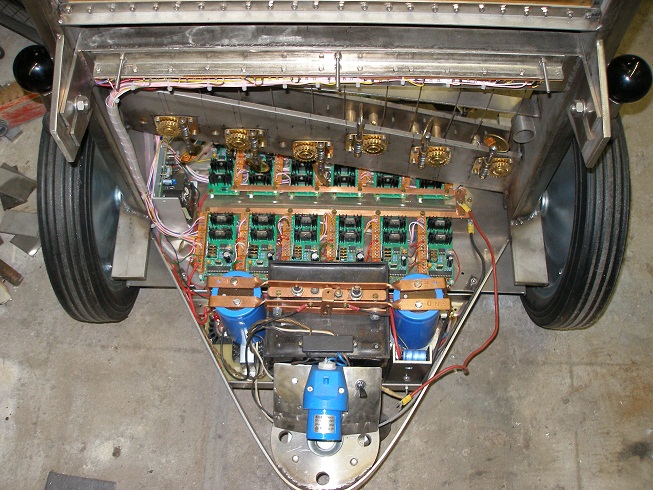

- 15.07.2010: Photo shoot by Troy Rogers and Laura Maes for illustrations
in the computer music journal.
- 26.07.2010: Three ebow drivers went to heaven in smoke stacks during code
testing... Somethings must go fundamentally wrong.
- 27.07.2010: Measurement session... Strangely enough, notes 36-39 work well,
but all others seem to refuse or burned out...
- 30-31.07.2010: Further measurements and signal analysis. Debugging PIC firmware...
The best string sound is obtained with multiplier values that are multiples
of five. The composition of the PWM signals clearly needs modifications.
- 01.08.2010: Inventary of damaged Mosfets and driver coils... Experimental
rewinding of a driver coil, using 0.8mm diameter copper wire on the coil former
from an 8 Watt rated Eagle 100V line transformer (ref.No. P037T). The original
winding had 80 turns for the 15 Ohm winding or a length of 7.30 m of copper
wire. The new winding has the same length. The original 100V winding was removed
entirely. Burned mosfets (BUZ345) will be replaced with IRF1310 or IRF3710Z
types.
- 02.08.2010: The new rewound coil has a DC resistance of 0.5 Ohm and an inductance
of 0.964 mH, measured without a string load. So, when we apply a PWM signal
with base frequency of 65Hz (midi note 36) and a duty cycle of 25%, the power
would be 40 W. Impedance measurements, using our Hameg impedance meter, gives
following results
| Measurement frequency |
impedance |
impedance with string load |
| 100 Hz |
0.69 Ohm |
0.76 Ohm |
| 120 Hz |
0.80 Ohm |
0.87 Ohm |
| 1000 Hz |
6.1 Ohm |
6.7 Ohm |
| 10000 Hz |
53.7 Ohm |
56.6 Ohm |
When we close the magnetic circuit, we measure again the original impedance
of 15 Ohms, measured at 1 kHz. [coil named C46B-Ea]
All power voltages rechecked: E-coil supply, without load: 16.9V, dropping
to 14.9 V with some load. Mosfet driver power supply: 15.15 V. Logic power:
5.04 V. Hammer & solenoid voltage (at no load): 40V.
Coil drivers for note 47 changed to use the 15 Ohm winding.
Second coil wound: this measures 1 mH and again 0.5 Ohm DC resistance.
- 03.08.2010: dsPIC board for note 40 removed: both BUZ345's had a complete
short, even the gate was fused to drain and source... This obviously explains
the burning out of both corresponding coils. Both mosfets replaced with IRF1310N
types. 7667 mosfet driver replaced and 40Vac VDR soldered over the power supply
connections for the coil drivers. Board tested o.k. with a double loudspeaker
dummy load.
dsPIC board for note 44 removed for repair: outer mosfet (BUZ345) burned out
and replaced with IRF1310N type. 7667 mosfet driver also replaced. At one
point we noted that the PWM output from the PIC when in a high state, only
measured +3.8 V... but it came out we were feeding the PIC from its midi input
pin... The firmware for this PIC however, has a bug: it sounds after proper
initialisation midi note 40 instead of 44.
dsPICboard for note 46 removed: inner mosfet (BUZ345) burned out. Replaced
with IRF1310N. 7667 appeared o.k. VDR placed across power supply. The firmware
is also in error here, since it sounds midi note 42 instead of 46.
dsPICboard for note 41 removed: inner mosfet (BUZ345) burned out. Replaced
with IRF1310N. 7667 driver replaced as well and VDR placed across power suppy.
dsPIC board for note 43 removed: innermosfet (BUZ345) gone, this time not
fused but realy burned to flames... Replaced with IRF1310N. VDR placed across
power supply pins.
Although all clamping diodes measured out ok, we are considering replacing
them with power zener diodes rated between 6.2 V and 10 V. In hurdy this led
to a much improved sound output. Third coil wound, measuring 1.3mH.
- 04.08.2010: Coil nr.4 wound. Measurement: Inductance 1.23mH, resistance:
0.57 Ohm. Impedance at 1000 Hz: 7.7 Ohm. Circuit drawing applying to these
newly wound coil drivers:
The copper wire used is SWG21, 0.8mm thick, surface 0.5 mm2. At a current
density of 3 A/mm2 the allowable continuous current becomes 1.51 A. Resistance
of this copper wire is 3.49 Ohm/100 m, or for a resistance of 1 Ohm, 28.8
m of wire are required. Occupied winding space is 118 windings/ cm2 of coil
former space. Farnell order nr. 1230984, on rolls of 0.5 kg.
Bug in the firmware revealed: in order to sound note 36, controller 20 has
to get the value 40. GMT test code adapted accordingly. This explains of course
the odd behaviour we noticed with the 5th harmonic...
- 05.08.2010: Frontal bow assembly loosened from chassis. Burned out coils
for notes 40, 43, 44 (Philips type) removed. Core and coil former saved and
rewound. Measurement for coil 40: Impedance at 1000 Hz = 8.45 Ohm, rising
to 10 Ohm with string load. DC resistance : 0.55 Ohm. Coil inductance: 1.37
mH. For later reference, lets call this Coil 40 front.
Coil 43, frontal bow, rewound: measurement: L= 1.34mH, Rdc= 0.5 Ohm, Z at
1000 Hz: 8.5 Ohm. Coil 44, frontal bow removed and replaced with a rewound
Eagle core coil (coil 4 in order of winding). This coil, since it differs
5mm in building height, was placed on a small aluminium plate 5mm thick.
Mounting of the repaired coils with Parabond 600 on the front bow. The front
bow should be completely repaired now. We have to wait for testing until the
Parabound is set.
Back bow burned coils 40, 41, 43, 46 removed.
Coil 43, back bow, rewound: measurement: L= 1.39mH, Rdc= 0.5 Ohm, Z at 1000
Hz: 8.7 Ohm.
- 06.08.2010: Coil 43, Back bow used as Coil 41 and mounted in place. Coil43B
replaced with a rewound Eagle core, 1mH. C40B replaced with third rewound
Eagle coil (1.3mH).
Back bow mounting of all coils with Parabond 600. After curing, we can bring
the bow in place again, resolder the wires and restart testing and evaluation.
After electric check out, it appeared that the wires commanding note 43 are
molten together and shorted. Back bow brought back in place. Tests using GMT
code.
- 07.08.2010: Aeio demonstration and firmware discussion with Johannes Taelman.
- 11.08.2010: Aeio already gets a part to play in Xavier Verhelst's orchestrations
for the upcoming 'Albion' concert with the robot orchestra.
- 12.08.2010: New coil rewound: 1.415mH, DC resistance: 0.52 Ohm, impedance
at 1 kHz: 8.9 Ohm. Philips core. This is a spare, for testing purposes. Another
coil (ex 41). rewound with 1 meter extra wire -thus filling the entire winding
space- on a Philips core. Measurement results: Inductance 1.9 mH, resistance
0.65 Ohm, impedance at 1 kHz: 12 Ohm. Both coils potted in epoxy resin.
- 13.08.2010: Amicus compiler purchased to program our parser PIC. This works
under MPLAB. However, it will take a few weeks before we anticipate to become
fluent with it.
- 15.08.2010: we got the amicus compiler and MPLAB to work together.
- 16.08.2010: First version for a midi-parser written for the Amicus platforms.
- 19.08.2010: Aeio played its first couple of notes in the M&M Albion
concert...
- 25.08.2010: We got the first ossature for a master controller for Aeio ready
in the Amicus compiler running under the platform MPLAB.
- 29:08.2010: The real time multitasking system is implemented now on the
Amicus board. We ordered the Proton+ compiler, such as to allow us to use
also other PIC controllers than the 18F25K20, a 3V device...
- 01.09.2010: Running into problems with the implementation of polyphonic
playing: how can we handle the note-offs in the case that two strings sound
a same note... The best solution seems to consist of using multiple channels.
The first prototype version of the parser software in now ready on the Amicus
platform.
- 02-04.09.2010: Further debugging, testing and developing of the firmware
for the master controller.
- 05.09.2010: Start building up of the hardware for the master controller
board, with a display for the strings playing. Rehearsal of <Robobomi>
with Dominica Eyckmans, a piece with an important part for <Aeio>.
- 06.09.2010: Parser board finished on prototype board. Here is the circuit:
 The twelve LED are
mounted to let users see which string(s) are playing the requested notes.
Hence their arrangement as a 'keyboard'. Since there are no black and white
LED's on the market, we went for yellow and red... The 3-state octal buffer/line
driver was used to adapt the 3.3V levels from the PIC processor, to standard
TTL levels as required to drive Mosfets.
The twelve LED are
mounted to let users see which string(s) are playing the requested notes.
Hence their arrangement as a 'keyboard'. Since there are no black and white
LED's on the market, we went for yellow and red... The 3-state octal buffer/line
driver was used to adapt the 3.3V levels from the PIC processor, to standard
TTL levels as required to drive Mosfets.
- 07-08.09.2010: Further work on the parser software as well as on the test
software in GMT.
- 09.09.2010: Midi parser Version 1.0 ready. Lights implemented as well. As
yet, two voices only.
- 11.09.2010: Completion of firmware for the dsPIC's with Johannes Taelman.
The dampers as well as the exciters are implemented and functional now.
- 12.09.2010: Version1.1 of the midi parser. Adapted to the newly implemented
features in the dsPIC software. Experimental construction of dampers with
foam from packaging material. Seems to work better than felt. Of course, this
is not a very durable material and would have to be replaced quite often.
The hammers work quite well as exciters, particularly at very low velocities
and for the very lowest frequencies. They do not help to speed-up sound build
up at higher partials.
- 13.09.2010: Further work and improvements on the parser firmware.
- 14.09.2010: Inharmonicity measurements on the overtone series of the actual
strings.
- 15.09.2010: Parser version 1.2: now note pressure (aftertouch) also implemented.
- 16.09.2010: Aeio survived his first public concert pretty well.
- 18.09.2010: Parser version 1.3. With new interrupt handler and double buffer
mechanism.
- 19.09.2010: Two yellow 1W LED lights mounted as well as a red SMD-LED light
strip under the damper assembly. For some reason the dsPIC for note 46 went
to heaven: latchup condition, drawing 1A on 5V for no apparent reason.
- 20.09.2010: Parser version 1.4. dsPIC for note 46 replaced.
- 23.09.2010: Parser version 1.5 flashed.
- 26.09.2010: Low level interupt coding and midi input buffer mechanism simplified
and improved. Parser version 1.6.
- 05.02.2011: Aeio gets an important part in 'Polyamori', namuda study #12.
- 18.05.2011: Video recording made with <Aeio> for the Computer Music
Journal. Camerawork by Laura Maes.
- 16.07.2011: Aeio gets an important section in our Namuda-Dyptich production
for 20th and 21th of july, with dancers Emilie De Vlam and Dominica Eyckmans.
- 06.11.2011: Smoke stack came out from string driver for note 41... Composition:
'Elfjes', namuda study #19. We have to check the coils as well as the mosfets.
- 08.11.2011: Check out for the note 41 failure.
- 11.11.2011: Frontal coil for note 41 burned out. This was 0.56mH Philips
orig. and will have to be replaced. BUZ345 to be checked. Aeio has an important
part in Namuda Study #19, 'Elves'...
- 16.11.2011: Coil replaced with a rewound C41F (1.9mH, 0.65 Ohms)
- 09.07.2013: Three of the wooden combs replaced with small 2mm thick aluminium
combs, tapered at the end. This does effectively sound better and reduces
string inharmonicity somewhat. Ideally we should use titanium, if we could
only get it somewhere...
- 15.07.2013: Titanium ordered from Titane Services (www.titane-services.eu),
a French business.
- 20.07.2013: Ordered Titanium came in, so the construction of bridges using
this metal can start off. Cutting out bridges from 2mm thick titanium posed
some new problems: the grinder when applied to the metal causes extremely
bright white sparks, necessitating the wearing of darkened safety goggles.
Filing and sanding is possible with the normal tools. Sawing with a manual
hacksaw is possible but fairly tedious. We will not even try plasma cutting,
as the material might take fire at the temperatures involved in the presence
of oxygen and nitrogen. TIG welding ought to be possible...
- 01.08.2013: The titanium bridges sound very well, but behave a bit unstable
at high string excitation levels. This is mainly because the material is too
thin.
- 18.02.2016: Aeio gets a dominant role in our 'Oorsprong' production with
Emilie De Vlam, Marijs Boulogne and Lara Van Wynsberghe.
- 01.08.2017: Aeio set up again in the orchestra for two demo concerts on
august 4th.
- 19.10.2017: Start design of a new parser board, using a 16 bit processor.
- 20.10.2017: Starting design of a PCB for the parser. We will use two processors:
an 8-bit 18F2525 for the lights and a 16-bit 24EP128MC202 for the parser.
This is the single sided PCB:
- 21.10.2017: Parser boards design finished. PCB etched, drilled and soldered.
This is the circuit drawing:
- 22.10.2017: Firmware for the lites processor on the parser board. Here is
the source code: Aeio_Lites.bas.
This tests o.k. Start working on the translation of the V1.6 code for the
parser to the new 16 bit platform. We can use some coding developed for the
Mirrored-X firmware, as this uses double buffering for MIDI I/O.
- 23.10.2017: Finalising firmware for the parser processor. Here is the source
code: Aeio_parser.bas . Blue power
LED's ordered for the parser board: OMC, type T21B1. Mounting of the board
on the Aeio chassis. Construction of a protecting top plate in polycarbonate.
Here is a picture of quite deserted parser board:
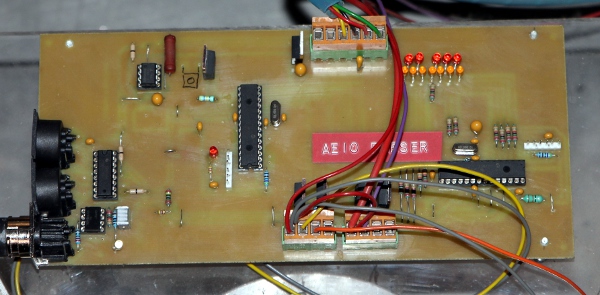
- 24.10.2017: Ordered blue power LED's came in, so we mounted one of them
on the parser board. Further testing and debugging: lite 6 is not working.
Note 47 board looks dead. Maybe this is the documented crash on overload...
Test code in GMT extended. Testing revealed nothing wrong with the parser
board as to the functionality of lite 6. Must be either the socket or the
light itself. Note 47 crashing seems persistent and certainly not due to any
fault in the parser board nor in its firmware. Mounting of the parser board
with protective shield in polycarbonate finished.
- 25.10.2017: Start work on making Aeio operate as a stand-alone gesture controlled
robot. This is the circuit for the radar sensor board to be used:
 It is a further development of the two radar boards we used for the automation
of our <Rodo> robot. So, for the firmware, we can start from what we
already developped there. This is the PCB for the radar3 board:
It is a further development of the two radar boards we used for the automation
of our <Rodo> robot. So, for the firmware, we can start from what we
already developped there. This is the PCB for the radar3 board:  Of course we will have to design a way of mounting this board on the <Aeio>
robot. To make wiring easy, we will have to feed this board with +5V via the
MIDI cable. This involves some minor changes on the parser board.
Of course we will have to design a way of mounting this board on the <Aeio>
robot. To make wiring easy, we will have to feed this board with +5V via the
MIDI cable. This involves some minor changes on the parser board.
- 26.10.2017: Looks like radar and automated instrument mode will have to
be mutually exclusive. In radar mode, we have to connect the radar-board output
to the midi input on the parser board. The radar board will be permanently
mounted on the <Aeio> chassis.
- 27.10.2017: Further work on the radar sensor firmware. This is what Aeio
looks with the radar board mounted:`
- 28.10.2017: Mechanics for mounting of the radar sensor board on the robot
constructed. The 5V power for the sensor board will be provided through the
midi-output cable: pins 5 and 1 carry the +5V power supply voltage. Make sure
a 5-pole cable is always used between the sensor board and the parser input.
Short 5-pole coiled cord made with 5-pole din connectors both ends, recycling
an old -but never used- PC-XT computer keyboard cable. To avoid possible shorts,
we filled the DIN connectors with Loctite Red silicon gasket compound before
assembling the two shelves. Full curing takes about 24 hours.
- 29.10.2017: Further work on the gesture recognition code in the radar firmware.
Radar board mounted on Aeio: first tests.
- 30.10.2017: Shaky behaviour of the radar observed. Measurement revealed:
heavy oscillations on the +5V power supply... A redesign of the power supply
seems required. Here is an updated circuit drawing:
 For the shaky 5V, we now use a Traco module, delivering 8A. It's a switcher
operating at about 130 kHz. The ripple is specified as 90 mV pp, without output
capacitor.
For the shaky 5V, we now use a Traco module, delivering 8A. It's a switcher
operating at about 130 kHz. The ripple is specified as 90 mV pp, without output
capacitor.
- 31.10.2017: Traco power module mounted and tested. Now the radar works o.k.
No more oscillations observed. Start writing test code for the radar board
in GMT.
- 01.11.2017: Further development of radar code. Log. mapping of amplitudes
changed again to linear.
- 02.11.2017: Changes in the radar firmware: now we pass through all incoming
midi -if implemented on aeio- to the output. This way the radar can work together
with external commands. If this is done, however, an extra latency of ca.
1.5 ms is introduced. Controller #79 introduced to switch interactive mode
on or off. By default on cold boot, it is on if the radar board is connected
to the parser board. Controllers #70 to #79 have no effect if midi is connected
to the parser board directly.
- 03.11.2017: Data acquisition code improved for the radar board. The radar
itself suffers a bit under mechanical or electromagnetic feedback from the
robot itself. Experimenting with lead screening on the backside of the radar
sensor. Orange cap mounted over bright white LED on the radar board, as it
was way too bright.
- 04.11.2017: Filter coefficients for the radar firmware recalculated using
c = EXP(-2.Pi.f / samplingrate). Integration and differenciation parameters
adapted accordingly.
- 05.11.2017: 'Aeio Rising' and 'Aeio Sinking' pieces tested and found to
be o.k. now. A still remaining problem is the mounting of the radar board:
we still suffer from mechanical feedback.
- 06.11.2017: Aeio demonstrated as a stand-alone robot to Laura Maes. Construction
of a damping mount for the radar assembly. This substantially improved mechanical
feedback between instrument and radar interface board. Also, it inherently
avoids possible ground loops, as it isolates the board electrically from the
robot chassis. Start working a a new embedded composition: 'Aeio's Response'.
This ought to be a pretty straight mapping of gesture properties on behavior
of the robot. Checking why the right (trebble side) yellow spotlight fails.
- 07.11.2017: Recheck of the parser board. A 2.2 Ohm metal film resistor -although
new- found to be defective. This explains the non functioning of the trebble
side yellow spotlite. Copper side of the parser board lacquered to prevent
corrosion. Controller 114-119 implemented such that the durations for the
embedded compositions can be changed. <Aeio> is ready now for stand-alone
operation.
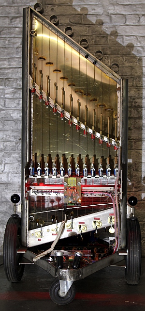 Some
new pictures made, including the new features.
Some
new pictures made, including the new features.
- 19.11.2017: <Aeio> integrated in our show for 'Kinderkunstendag'.
Worked flawless.
- 21.11.2017: <Aeio> presented, together with six other robots of ours,
at the EU-Robotics conference in Brussels. It's the very first time <Aeio>
leaves our buildings.
- 23.11.2017: <Aeio> played its embedded compositions with butoh dancer
Emilie De Vlam. Here is a link
to a photo shoot on this production.
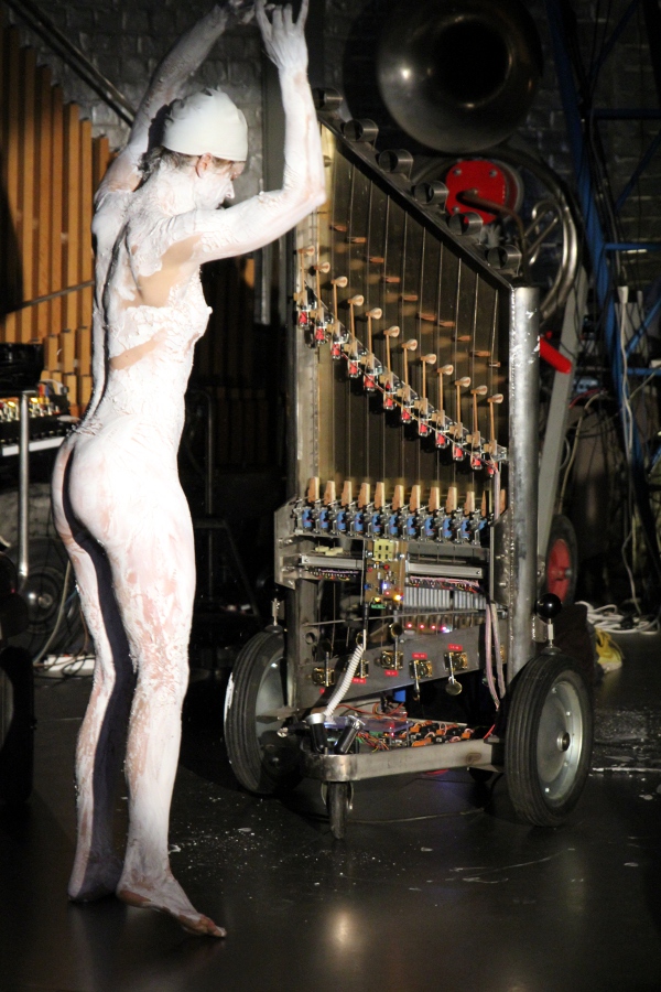
- 24.11.2017: Robot cleaned up after yesterdays performance.
- 28.04.2018: Discussion with the director of the Speelklok Museum in Utrecht:
we need to change the interactivity code and implementation to adapt it to
the specific context of the museum setup. Also we should design it such that
it can work continously for a period of nealy six months. The modifications
will be part of the festivities around the 50th anniversary of Logos.
- 07.09.2018: Extra module added using an Axoloti board such that Aeio can
be tuned without an external computer connected. Also it now will be capable
of playing an embedded demo composition.
- 08.09.2018: This is the circuit:
 Note hat the board gets it's power via the MIDI-connector. Pins 1 and 3 carry
+5V. So, a 5-wire cable must be used. The 12-position rotary switch mounted
on the left side of the parser board, allows tuning. The positions of the
switch reflect the chromatic scale C to B. The 6-position rotary switch on
the right side is used to select the mode of operation: radar control , demo
files.
Note hat the board gets it's power via the MIDI-connector. Pins 1 and 3 carry
+5V. So, a 5-wire cable must be used. The 12-position rotary switch mounted
on the left side of the parser board, allows tuning. The positions of the
switch reflect the chromatic scale C to B. The 6-position rotary switch on
the right side is used to select the mode of operation: radar control , demo
files.
- 12.09.2018: Functionality of the right side rotary switch is documented
here:
 These are the named
connections to the Axoloti board:
These are the named
connections to the Axoloti board: 
- 13.09.2018: <Aeio> left of to Utrecht to the Speelklok Museum. It
will return to join the orchestra again around march 2019.
- 07.03.2019: <Aeio> returned safely from the Speelklok Museum in Utrecht,
where it played every day for six months.
- 17.11.2019: <Aeio> at work in interactive mode for Kinderkunstendag.
- 27.09.2021: After playing uninterrupted for 25 days in the SMAK museum,
<Aeio> returned to the robot orchestra in perfect condition.
- 18.12.2022: Discovered and used by Gamut Inc. during their one week residency
at Logos.
- 25.10.2024: Failure reported by Hans Roels for note 41. We need to check
the dsPIC board as it seems neither e-bow nor damper and hammer show signs
of life.
- 27.10.2024: A splash of solder discovered on the surface of the board steering
note 41. After removing the solder splash, the board still remains deaf. One
of the power mosfets measures shorted or else the electromagnet is burned
out or open-circuit. Maybe we should consider to apply the research results
on the redesign of the ebow mechanism in <Rodo>.
- 29.10.2024: Board for note 41 works if we loosen the e-bow coil connector...
One of the +12V pink power lines found cut: why did we (?) do this? Back MOSFET
found burned. Actually, the back MOSFET for note 45 appears to be shorted
as well. These are the MOSFET's steering the coils on the front bow.Looks
like it's about time for a complete thorough test and repair of this robot...
- 30.10.2024: Board for note 41 removed for testing. In the lab, we cannot
find failures... Note: for testing we needed to recompile the GMT software
for Aeio with support for the dsPIC boards enabled. The test-tasks for these
boards are located in the fourth column in the user interface. They are hard-coded
to work only on midi-port 0. Dont forget that all these boards have identical
firmware and all of them respond to midi channels 0-11.
- 31.10.2024: Maybe we should also check the wiring between this board and
the parser. Is the midi-wire well connected? Circuit drawing for the dsPIC
boards redrawn:
- 01.11.2024: PCB for note 41: Capacitor between pins 19 and 20 replaced with
a 10uF tantalum type. This conforms to the value in use on our 24EP256MC202
types. Board 45 removed as we found the mosfet for the front bow shorted.
A piece of crap metal was found on the PCB. On board 45, both MOSFET's replaced
with IRF135 types.
- 02.11.2024: PCB's 41 and 45 tested o.k. Unsurmountable problems in reassembling
board 41 in the robot as the M4 thread of the positive power supply copper
strips became badly damaged... Even after one hour of work we couldn't get
the job done... In the meanwhile, we designed a new dsPIC programming board
to accomodate the dsPIC30F3010 chips.
- 03.11.2024: PCB's placed back. The boards work fine, but the coils on the
frontal ebow are opencircuit or disconnected. These need to be replaced, read
rewound on the E cores. There appears to be a problem wih board 47: when selected
and playing it activates the damper for no reason... dsPIC crashing?
- 08.11.2024: Board 47 removed for examination in the lab. All functional
tests passed. Let's try increasing the values of some bypass caps: 10uF between
pins 19 and 20 and soldering a 40V ac VDR across the solenoid power supply
pins.
- 09.11.2024: Frontbow coils 41 and 45 confirmed to be burned out. Seems line
we used the same type of loudspeakertransformer the the 3-phase stormwind
controller in version 1.0 of the <Thunderwood> robot. We found the old
circuit back and we now can consider to recycle those three transformers for
rewinding and repairing <Aeio>.
- 10.11.2024: Frontal bow assembly removed for repair. Coil 41 and 45 fully
molten... (Coil 41 was 1.9mH on a Philips core). Coil 41:
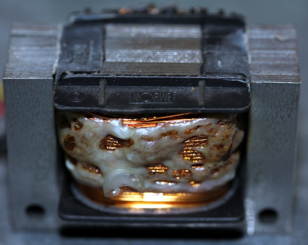 Rewinding
coil 41 using 1 mm diameter copper wire. (AWG18, 0.78 mm2). The old winding
was diameter 0.65 copper wire (AWG23/24, 0.5 mm2). Coil former for coil 41
filled, ca. 70 turns of copper wire (we lost count...). Measured inductance
now: 566uH, Q-factor 3, DC resistance 1.3 Ohm (?). We removed all windings
from the core prior to rewinding. Coil 41, new:
Rewinding
coil 41 using 1 mm diameter copper wire. (AWG18, 0.78 mm2). The old winding
was diameter 0.65 copper wire (AWG23/24, 0.5 mm2). Coil former for coil 41
filled, ca. 70 turns of copper wire (we lost count...). Measured inductance
now: 566uH, Q-factor 3, DC resistance 1.3 Ohm (?). We removed all windings
from the core prior to rewinding. Coil 41, new: 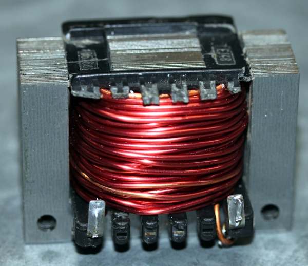 Same
for the front coil for note 45. Here after winding, measured inductance was
554uH, Q-factor 3.02. New coils potted in epoxy rosin. Molten coil 45:
Same
for the front coil for note 45. Here after winding, measured inductance was
554uH, Q-factor 3.02. New coils potted in epoxy rosin. Molten coil 45:  New coil 45 front:
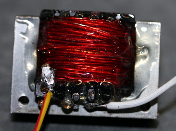
- 11.11.2024: Both coils 41 and 45 in the front bow glued in again. Tests
on coils 36,37,38 as they strongly smell phenol... Coil in frontbow for note
38 found molten. So, we have to rewind this one as well. Coil rewound with
4 layers of 1mm diameter copper wire. Measurement of inductance after reassembling
the coil: 576uH at 100Hz, 564uH at 1kHz, 522uH at 10kHz and 341uH at 100kHz.
Measured Q factor: allways around 3.0. The dc resistance (hard to measure
with our equipment...) is in the order of 0.1 Ohm. If we recalculate the working
conditions for this coil we get an impedance Xl = 2.Pi.f.L + Rdc = 0.36 Ohm
(note 38 = 73.4Hz, L= 576 uH). The maximum voltage we can apply would then
be 1.9V rms. So the sine wave pp voltage shoud be limited to 5.27V. However,
in <Aeio> the duty cycle of the applied square waves is always smaller
than 25%, thus the working voltage should not exceed 7.6 V. It will be clear
that for higher frequencies, conditions become a lot more relaxed.
- 12.11.2024: Coil for note 38 glued in the front bow assembly. Waiting for
curing before we can reassemble and test... Check note 43 now. All components
reassembled and connected. Ready by the end of the working day. Testing in
GMT: all strings sound like working fine. On maximum load, the voltage for
the driver-coils sinks to 14.2 V. This is perfectly o.k. On first tests, no
more crashing on board 47.
Most recent note/driver/component placement:
| |
front coils & bow |
back coils & bow |
front mosfet |
back mosfet |
PIC state |
remarks |
| 36 |
0.56mH Philips orig. |
0.56mH Philips orig. |
BUZ345 |
BUZ345 |
o.k. |
|
| 37 |
0.56mH Philips orig. |
0.56mH Philips orig. |
BUZ345 |
BUZ345 |
o.k |
back coil suspect. |
| 38 |
0.576mH Philips rewound gwr nov 2024 |
0.56mH Philips orig. |
BUZ345 |
BUZ345 |
o.k |
frontcoil rewound 11.11.2024, 1mm copper wire |
| 39 |
0.56mH Philips orig. |
0.56mH Philips orig. |
BUZ345 |
BUZ345 |
o.k. |
|
| 40 |
1.37mH -C40F-Ph |
1.3mH - C40B- Eag |
IRF1310 |
IRF1310 |
o.k. |
|
| 41 |
0.566mH C41F rewound gwr nov.2024 |
1.39mH -C41B-Ph |
BUZ345 |
IRF1310 |
o.k |
frontcoil rewound 10.11.2024, 1mm copper wire |
| 42 |
0.56mH Philips orig. |
0.56mH Philips orig. |
BUZ345 |
BUZ345 |
o.k |
|
| 43 |
1.34mH -C43F-Ph |
1mH- C43B-Eagle |
BUZ345 |
IRF1310 |
o.k. |
wire shorted ? |
| 44 |
1.23mH- C44F- Eagle |
0.56mH Philips orig. |
IRF1310 |
BUZ345 |
o.k. |
|
| 45 |
0.554mH, Philips core - rewound 2024 |
0.56mH Philips orig. |
IRF135 |
IRF135 |
o.k. |
frontcoil rewound 10.11.2024, 1mm copper wire. |
| 46 |
2mH Eagle orig. |
1mH -C46B-Eagle |
BUZ345 |
IRF1310 |
o.k. |
|
| 47 |
2mH Eagle orig. |
2mH Eagle orig. |
BUZ345 |
BUZ345 |
may crash |
dsPIC crashes on overload, bypass caps added 2024 |
memo: the mosfets controlling the front bow coils are situated on the outside
of the dsPIC boards.
Last update: 2024-11-12
by Godfried-Willem Raes
Further reading on this topic (some in dutch):
Bibliographical references:
ROSSING, Thomas.D (editor), "The
Science of String Instruments" , ed: Springer NY, Stanford CCRMA, 2010
ISBN 978-1-4419-7109-8
MDU1100t X-band radar
sensor datasheet (Microwave Solutions, UK)
Technical data sheet, detailed midi-implementation, design calculations and
maintenance instructions:
Technische gegevens, ontwerpberekeningen en instrukties voor onderhoud en demontage:
- 24 Electromagnetic string drivers: modified loudspeaker line transformers
(I-mu-metal removed from transformer, the original transformer has alternating
E-I and I-E core metal) . Original manufacturer: Philips, type LBC 3174/01
or LBC3024/00. NC 8901 317 40101 (Nr.082256 - No.082293), made in W.-Germany.
Windings 0-4-8 Ohms, secondary. Primary 1.5W, 3W, 6W / 100V. The DC resistance
of the 8 ohm speaker winding is 1.65 to 1.9 Ohms, depending on temperature.
Continuous DC current should be limited to 2A if the power rating is not to
be exceeded. The original inductance of the coil at 1kHz was 1mH, but after
removal of the I-core, this value dropped to 0.56mH. The combined ac/dc impedance
of the original 8 Ohm winding now becomes 5.3 Ohms. The maximum ac rms voltage
that can be applied to the winding now is 5.64V. With 50% duty cycle square
waves this leads to a maximum voltage of 8V. For 25% duty cycle the maximum
voltage becomes 11.3V, hence our choice for a 12V power supply.
Some of the windings on these cores have been rewound by us with 0.8mm (SWG21)
enameled copper wire. With the new winding, the inductance becomes 1.3 to
1.4 mH and the DC resistance 0.5 Ohms. Power handling capacity is thus greatly
enhanced.
- Alternative transformer type: Eagle, 100V line transformer, type MT-8W,
ref.nr P037T Primary 1W,2W,4W,8W / 100V. Secondary 8 Ohms and 15 Ohms. (Obtainable
from Farnell). Inductance of the 8 Ohm winding after removal of the I-core:
1.3mH. DC resistance of the winding: 0.92 Ohm. Inductance of the 15 Ohm winding:
2mH. DC resistance 1.13 Ohm. The presence of the steel string does influence
the inductance. The inductance of the 8 Ohm winding of the original transformer
was ca. 7.3 mH. This type is used for the two highest strings.
- Tuning pins: double bass type. (3 sets of 4 screws)
- String dampers: made from teak-wood, length 80mm, with 10mm. Felt thickness:
10mm. See drawings in the logbook.
- Damper solenoids: August Laukhuff, 24V trakturmagnet. DC-resistance: 90
Ohms. Current: 266mA. The 24V power supply has to be rated for 3.5A minimum.
- Exciter hammer solenoids: August Laukhuff, 12V action magnet. DC-resistance
75 Ohms. Current 190mA. These solenoids are driven with variable duration
pulses on 24V. Same power supply as the dampers, since hammers and dampers
are never driven together, the rating of the 24V power supply is unaffected.
- Exciter hammers: taken from an old upright piano, central octave. Hammerhead
felt sligthly brushed up and hardened again.
- Wheels: large wheels: diameter 400mm, axis 25mm, width:73mm. Small wheels:
diameter 144mm, axis 10mm, width 50mm. These wheels are mounted on the flanges
with M10 x 20 stainless steel hexagonal bolts.
- In case the soundboard needs replacement: Material: Hardened brass MS58,
werkstof nr. 2.0401, ASTM 360, AFNOR UZ39PB2. Sheet thickness 0.8mm.
- Transformer used for the string drivers: EREA E12SC630S, 630VA. Output:
12V / 52.5A
- Transformer used for the 5V power supply: Farnell 117-2363, 12VA, 230V :
2 x 6V.
- Transformer used for the 24V power supply: ILP toroidal 80VA, 220V : 2 x
22V, 2 x 1.81A. Order nr.8022 type 31015.
- Power supply for the mosfet drivers: Power One, HB15-1.5-AG. Farnell order
nr.81763357, 15 Volt - 1.5A analog regulated, open frame chassis. Primary:
100/120/220/230-240V.
- Power supply module for the logic supply at +5V: Traco TMM40-105, 8A.
- Power supply circuit:
- Component list and values for each of the twelve PC boards:
- R1: 220 Ohm
- R2,3,4,5,6,7: 10 kOhm
- R8: 330 Ohm
- IC1: LM7810, voltage regulator
- IC2: dsPIC 30F3010
- IC3: ICL 7667, dual inverting mosfet driver
- D1, D2: BYV32, double diodes in TO220 package
- C2, C5: 100 uF, tantaal (25V)
- C1: 1mF, elko (16V)
- C9, C10: 33pF
- Q7: Crystal 15MHz
- D3, D4: SF52 (5A, 100V, 35ns)
- Q1, Q6: BUZ345 Mosfet [no longer in production], can be replaced with
IRF1310 or even better, IRF135B203
- Q2, Q3, Q3, Q4: IRL640 or IRLZ44, Mosfet (TO220)
- LED1: green LED, 3mm
- LED2: red LED, 3mm ( TLHR4405)
- Wiring of the connectors on the twelve note driver boards:
- Removal of the string driver printed circuit boards: A board can only be
removed after complete removal of the positive voltage copper power rail on
the corresponding row. The M4 bolt connecting the boards to the ground rail
is only accessible after removal of the upper rail. Note that all bolts and
nuts used in this assemby are brass, including the washers.
- Blue 1W LED on the parser board: T21B1, OMC, TO220, 465nm, 10 Lumen, 350mA,
Vf= 3.5V.
- <Aeio> uses a single midi channel (1) for its commands from the outer
world. However, each dsPIC board listens to its own channel (0-11) and these
boards receive the translated midi commands from the parser board. Hence the
midi implementation for these dsPIC boards is fully different from the 'general'
midi implementation for users. Also, the radar interface board, has a series
of specific controllers implemented. Here is a table with the detailed implementation
and the correspondences:
-
| Midi commands received by the parser board on midi channel
1 only |
Translation for the dsPIC's
Each pic on a different channel 0 - 11.
|
Function |
Midi commands for the Radar board, channel 1 only. |
Function |
| Note-off + release |
Note-off + release on a channel 0 - 11.
(in general the channel = note mod 12)
|
release steers the damping time for the dampers. CC64
must be 0 in order for this to work. |
|
passed thru for the note range 24 to 127 and 0 to 6 |
| Note-on + velo |
Sends Controller 69 on a channel 0 - 11, depending on the note played
depending on the setting for basenote:
if basenote = 0:
Note 36 + velo on a channel 0 - 11
if basenote = 1:
Note 48 + velo on a channel 0 - 11
if basenote = 2
Note 60 + velo on a channel 0 - 11
if basenote = 3
Note 72 + velo on a channel 0 - 11
if basenote = 4
Note 84 + velo on a channel 0 - 11
end if
Controller 22 on a channel 0 - 11 with value = controller 22 (multiplier)(controller
100-111)
Controller 24 on a channel 0 - 11 with value = Tuningbyte (controller
80-91)
Controller 3 on a channel 0 - 11 with value = velo
Controller 4 on a channel 0 -11 with value = velo
(in general the channel = note mod 12)
|
notes 24 to 35 are hammers
ctrl 69 = ebow on off switch
the velo bit is disregarded by the dsPIC as it is translated to settings
for controllers 3 and 4.
notes 36 to 127 are ebow notes
|
|
passed thru for the note range 24 to 127 and 0 to 6 |
| Note + Pressure |
Controllers 3 and 4 on channels 0 - 11
(in general the channel = note mod 12)
|
note pressure steers the volume whilst a note is sounding |
|
passed thru for the notes 0 to 6 and 36 to 127 |
| Controller + value: |
|
|
|
|
| 7 + value |
7 + value sent to channels 0 - 11 on the dsPIC |
Volume control |
|
passed thru |
| 20 + value |
none |
flashing speed for the lights |
|
passed thru |
| 23 + value (default = 64) |
controllers 3 and 4 on all channels 0-11 |
global wave symmetry for all strings |
|
passed thru |
| 30-41 + value (default = 64) |
controllers 3 and 4 on a channel 0- 11 |
individual wave symmetry for the string boards |
|
passed thru |
|
50-61: set the tuning base for the strings. Users do not have to
set these controllers since the firmware sets the correct default
to the string tuning on cold boot.
It makes no sense to send these controllers unless a different tuning
is used, or different strings are placed on the instrument.
|
controller 20 + value to channel resp. 0 - 11 on the dsPIC
basic tuning. The range is 36 to 60.
|
sets the notes the dsBoards are tuned to.
Normally set to 36,37,38,39... 47
|
|
passed thru |
| 64 + value |
64 + value sent to channels 0 - 11 on the dsPIC |
0 = dampings enabled
>0 =dampers disabled
|
|
passed thru |
| 65 + value |
65 + value sent to channels 0 - 11 on the dsPIC |
enable noteoff with release. This only works if CC64=0 |
|
passed thru |
| 66 + value |
66 + value (0 or 64) sent to channels 0 - 11 on the dsPIC |
0 = power down
>0 = power on
|
66 + value |
by default CC66 is ON, to allow autonomous playing
passed thru
|
| |
|
|
70 + value |
dt interval for derivative of speed (accel)
default = 48 (dt=205ms)
|
| |
|
|
71 + value |
dt interval for derivative of amplitude (dS)
default = 82 (dt=202ms)
|
| |
|
|
73 + value |
sensitivity for 'AeioRising' and 'AeioSinking'
default = 36
|
| |
|
|
74 + value |
noise floor
default = 1 (minumum value is autoadjusting)
|
| |
|
|
77 + value |
dS multiplier
default = 1
|
| |
|
|
78 + value |
accelleration multiplier
default = 16
|
| |
|
|
79 + value |
default = 0
Radar disable
If > 0 the radar is disabled.
|
| 80-91: adjust the fine tuning for every individual string.
The range is -50 cents to + 50 cents. By default the controllers are
initialised to 64. |
Controller 24 to a channel 0 - 11 + value
The range is -50 cents to + 50 cents. By default the controllers
are initialised to 64.
|
fine tuning of the notes, quartertone up or down. |
|
passed thru |
| 100-111: set the flageolet multiplier value for a string
whilst it is sounding a note. By default all set to 1. Possible range
is 1 to 32. |
Controller 22 to a channel 0 - 11 + value on the dsPIC |
flageolet multiplier for the notes, range 1 to 32 |
|
passed thru |
| 112 + value |
- |
- |
112 + value |
sets radar base frequency |
| 114 + value |
- |
- |
114 + value |
sets the duration for embedded composition 1 in 72"
units. |
| 115 + value |
- |
- |
115 + value |
sets the duration for embedded composition 2 in 72"
units. |
| 116 + value |
- |
- |
116 + value |
sets the duration for embedded composition 3 in 72"
units. |
| 117 + value |
- |
- |
117 + value |
sets the duration for embedded composition 4 in 72"
units. |
| 118 + value |
- |
- |
118 + value |
sets the duration for embedded composition 5 in 72"
units. |
| 119 + value |
- |
- |
119 + value |
not yet implemented |
| 123 + 0 |
123 + 0 to channels 0 - 11 on the dsPIC |
all notes off command |
123 + 0 |
all notes off command
passed thru
|
| |
|
|
|
|
|
Program Change
values: 0,1,2,3
|
|
changes the tuning tables used.
Default = 2
|
values 16 and higher |
select embedded interactive compositions
selecting 16 to 19 enables the radar and reset Ctrl.79 to 0
Values 0 to 3 are passed thru
|
| Channel aftertouch |
not implemented |
|
|
blocked |
| Pitch bend |
not implemented |
|
|
blocked |
For further details, one should read the source code of the firmware.
- Source code for the parser board
- Source code for the radar sensor
board
- MDU1100t X-band
radar sensor datasheet (Microwave Solutions, UK)
Theoretical rounded overtone table based on modern acoustic research: [to be
completed]
|
snaar
noot
|
36
Do
|
37
Do#
|
38
Re
|
39
Mib
|
40
Mi
|
41
Fa
|
42
Fa#
|
43
Sol
|
44
Sol#
|
45
La
|
46
Sib
|
47
Si
|
poly |
| 36 |
1 |
|
|
|
|
|
|
|
|
|
|
|
1 |
| 37 |
|
1 |
|
|
|
|
|
|
|
|
|
|
1 |
| 38 |
|
|
1 |
|
|
|
|
|
|
|
|
|
1 |
| 39 |
|
|
|
1 |
|
|
|
|
|
|
|
|
1 |
| 40 |
|
|
|
|
1 |
|
|
|
|
|
|
|
1 |
| 41 |
|
|
|
|
|
1 |
|
|
|
|
|
|
1 |
| 42 |
|
|
|
|
|
|
1 |
|
|
|
|
|
1 |
| 43 |
|
|
|
|
|
|
|
1 |
|
|
|
|
1 |
| 44 |
|
|
|
|
|
|
|
|
1 |
|
|
|
1 |
| 45 |
|
|
|
|
|
|
|
|
|
1 |
|
|
1 |
| 46 |
|
|
|
|
|
|
|
|
|
|
1 |
|
1 |
| 47 |
|
|
|
|
|
|
|
|
|
|
|
1 |
1 |
| 48 |
2 |
|
|
|
|
|
|
|
|
|
|
|
1 |
| 49 |
|
2 |
|
|
|
|
|
|
|
|
|
|
1 |
| 50 |
|
|
2 |
|
|
|
|
|
|
|
|
|
1 |
| 51 |
|
|
|
2 |
|
|
|
|
|
|
|
|
1 |
| 52 |
|
|
|
|
2 |
|
|
|
|
|
|
|
1 |
| 53 |
|
|
|
|
|
2 |
|
|
|
|
|
|
1 |
| 54 |
|
|
|
|
|
|
2 |
|
|
|
|
|
1 |
| 55 |
3 |
|
|
|
|
|
|
2 |
|
|
|
|
2 |
| 56 |
|
3 |
|
|
|
|
|
|
2 |
|
|
|
2 |
| 57 |
|
|
3 |
|
|
|
|
|
|
2 |
|
|
2 |
| 58 |
|
|
|
3 |
|
|
|
|
|
|
2 |
|
2 |
| 59 |
|
|
|
|
3 |
|
|
|
|
|
|
2 |
2 |
| 60 |
4 |
|
|
|
|
3 |
|
|
|
|
|
|
2 |
| 61 |
|
4 |
|
|
|
|
3 |
|
|
|
|
|
2 |
| 62 |
|
|
4 |
|
|
|
|
3 |
|
|
|
|
2 |
| 63 |
|
|
|
4 |
|
|
|
|
3 |
|
|
|
2 |
| 64 |
5 |
|
|
|
4 |
|
|
|
|
3 |
|
|
3 |
| 65 |
|
5 |
|
|
|
4 |
|
|
|
|
3 |
|
3 |
| 66 |
|
|
5 |
|
|
|
4 |
|
|
|
|
3 |
3 |
| 67 |
6 |
|
|
5 |
|
|
|
4 |
|
|
|
|
3 |
| 68 |
|
6 |
|
|
5 |
|
|
|
4 |
|
|
|
3 |
| 69 |
|
|
6 |
|
|
5 |
|
|
|
4 |
|
|
3 |
| 70 |
7 |
|
|
6 |
|
|
5 |
|
|
|
4 |
|
4 |
| 71 |
|
7 |
|
|
6 |
|
|
5 |
|
|
|
|
3 |
| 72 |
8 |
|
7 |
|
|
6 |
|
|
5 |
|
|
4 |
5 |
| 73 |
|
8 |
|
7 |
|
|
6 |
|
|
5 |
|
|
4 |
| 74 |
|
|
8 |
|
7 |
|
|
6 |
|
|
5 |
|
4 |
| 75 |
9 |
|
|
8 |
|
7 |
|
|
6 |
|
|
|
4 |
| 76 |
|
9 |
|
|
8 |
|
7 |
|
|
6 |
|
5 |
5 |
| 77 |
10 |
|
9 |
|
|
8 |
|
7 |
|
|
6 |
|
5 |
| 78 |
|
10 |
|
9 |
|
|
8 |
|
7 |
|
|
|
4 |
| 79 |
11 |
|
10 |
|
9 |
|
|
8 |
|
7 |
|
|
5 |
| 80 |
|
11 |
|
10 |
|
9 |
|
|
8 |
|
7 |
6 |
6 |
| 81 |
12 |
|
11 |
|
10 |
|
9 |
|
|
8 |
|
|
5 |
| 82 |
|
12 |
|
11 |
|
10 |
|
9 |
|
|
8 |
|
5 |
| 83 |
13 |
|
12 |
|
11 |
|
10 |
|
9 |
|
|
7 |
6 |
| 84 |
14 |
13 |
|
12 |
|
11 |
|
10 |
|
9 |
|
|
6 |
| 85 |
|
14 |
13 |
|
12 |
|
11 |
|
10 |
|
9 |
|
6 |
| 86 |
15 |
|
14 |
13 |
|
12 |
|
11 |
|
10 |
|
8 |
7 |
| 87 |
16 |
15 |
|
14 |
13 |
|
12 |
|
11 |
|
10 |
|
7 |
| 88 |
|
16 |
15 |
|
14 |
13 |
|
12 |
|
11 |
|
|
6 |
| 89 |
17 |
|
16 |
15 |
|
14 |
13 |
|
12 |
|
11 |
9 |
8 |
| 90 |
18 |
17 |
|
16 |
15 |
|
14 |
13 |
|
12 |
|
|
7 |
| 91 |
|
18 |
17 |
|
16 |
15 |
|
14 |
13 |
|
12 |
|
7 |
| 92 |
19 |
|
18 |
17 |
|
16 |
15 |
|
14 |
13 |
|
10 |
8 |
| 93 |
20 |
19 |
|
18 |
17 |
|
16 |
15 |
|
14 |
13 |
|
8 |
| 94 |
21 |
20 |
19 |
|
18 |
17 |
|
16 |
15 |
|
14 |
11 |
9 |
| 95 |
22 |
21 |
20 |
19 |
|
18 |
17 |
|
16 |
15 |
|
|
8 |
| 96 |
23 |
22 |
21 |
20 |
19 |
|
18 |
17 |
|
16 |
15 |
12 |
10 |
| 97 |
|
23 |
22 |
21 |
20 |
19 |
|
18 |
17 |
|
16 |
|
8 |
| 98 |
24 |
|
23 |
22 |
21 |
20 |
19 |
|
18 |
17 |
|
13 |
9 |
| 99 |
25 |
24 |
|
23 |
22 |
21 |
20 |
19 |
|
18 |
17 |
|
9 |
| 100 |
26 |
25 |
24 |
|
23 |
22 |
21 |
20 |
19 |
|
18 |
14 |
10 |
| 101 |
27 |
26 |
25 |
24 |
|
23 |
22 |
21 |
20 |
19 |
|
|
9 |
| 102 |
28 |
27 |
26 |
25 |
24 |
|
23 |
22 |
21 |
20 |
19 |
15 |
11 |
| 103 |
29 |
28 |
27 |
26 |
25 |
24 |
|
23 |
22 |
21 |
20 |
|
10 |
| 104 |
30 |
29 |
28 |
27 |
26 |
25 |
24 |
|
23 |
22 |
21 |
16 |
11 |
| 105 |
31 |
30 |
29 |
28 |
27 |
26 |
25 |
24 |
|
23 |
22 |
|
10 |
| 106 |
32 |
31 |
30 |
29 |
28 |
27 |
26 |
25 |
24 |
|
23 |
17 |
11 |
| 107 |
|
32 |
31 |
30 |
29 |
28 |
27 |
26 |
25 |
24 |
|
18 |
10 |
| 108 |
|
|
32 |
31 |
30 |
29 |
28 |
27 |
26 |
25 |
24 |
|
9 |
| 109 |
|
|
|
32 |
31 |
30 |
29 |
28 |
27 |
26 |
25 |
19 |
8 |
| 110 |
|
|
|
|
32 |
31 |
30 |
29 |
28 |
27 |
26 |
|
7 |
| 111 |
|
|
|
|
|
32 |
31 |
30 |
29 |
28 |
27 |
20 |
7 |
| 112 |
|
|
|
|
|
|
32 |
31 |
30 |
29 |
28 |
21 |
6 |
| 113 |
|
|
|
|
|
|
|
32 |
31 |
30 |
29 |
|
4 |
| 114 |
|
|
|
|
|
|
|
|
32 |
31 |
30 |
22 |
4 |
| 115 |
|
|
|
|
|
|
|
|
|
32 |
31 |
23 |
3 |
| 116 |
|
|
|
|
|
|
|
|
|
|
32 |
24 |
2 |
| 117 |
|
|
|
|
|
|
|
|
|
|
|
|
|
| 118 |
|
|
|
|
|
|
|
|
|
|
|
25 |
|
| 119 |
|
|
|
|
|
|
|
|
|
|
|
26 |
|
| 120 |
|
|
|
|
|
|
|
|
|
|
|
27 |
|
| 121 |
|
|
|
|
|
|
|
|
|
|
|
28 |
|
| 122 |
|
|
|
|
|
|
|
|
|
|
|
29 |
|
| 123 |
|
|
|
|
|
|
|
|
|
|
|
30 |
|
| 124 |
|
|
|
|
|
|
|
|
|
|
|
31 |
|
| 125 |
|
|
|
|
|
|
|
|
|
|
|
32 |
|
| 126 |
|
|
|
|
|
|
|
|
|
|
|
|
|
| 127 |
|
|
|
|
|
|
|
|
|
|
|
|
|
Robody pictures with <Aeio>: