|
Musical Robot Research project on the development of new tools for musical expression at the Ghent University
|
|
<Zi>
an attempt to make an automated Qanun dr.Godfried-Willem RAES 2009-2016-2024 |
|
Musical Robot Research project on the development of new tools for musical expression at the Ghent University
|
|
<Zi>
an attempt to make an automated Qanun dr.Godfried-Willem RAES 2009-2016-2024 |
<Zi>
In our quite large collection of musical instruments at Logos Foundation, we had since long a bunch of different Zithers of different kinds: German made ones with some 48 steel strings, a Han-Koto as well as a few zithers stemming from 19th century musical automatons. For many years we had thoughts about finding a way to turn at least one of these into a musical robot. The problems, as soon as we started designing it on the drawing table seemed very unsurmountable. The main reason being the too close spacing of the strings. No matter what kind of plucking mechanism we imagined, it either took too much physical space (using bidirectional solenoids) or it would be way too slow and monophonic (using a sledge mechanism with a single plectrum) to allow automation of all of them. So the idea was dropped for many years.
In 2013 we were asked by Osama Abdulrassol to consider the
automation of an arabic Qanun. The same problems we had analysed
already reappearing and some new ones in top: the Qanun uses microtonal
pitchchanges using a mechanically pretty simple system (mandalar) , but
again due to size/force constraints, very difficult to automate well.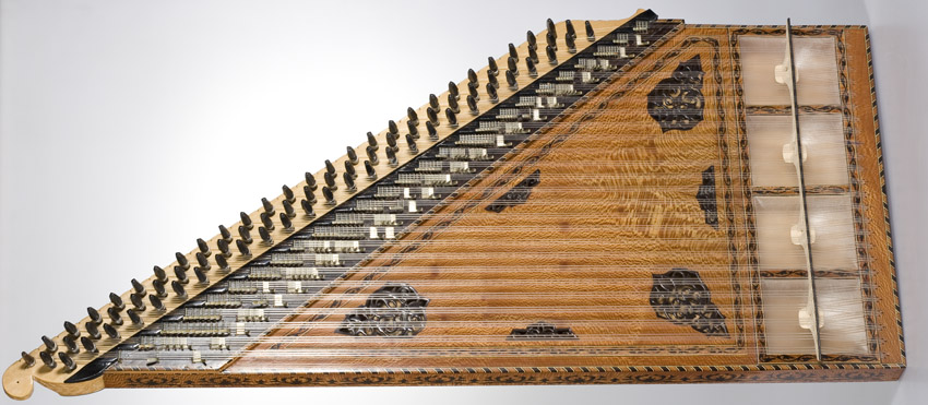
In may 2013 we decided to have a throw at it, and started making a first prototype
for a plucking mechanism. The perspective being to also make the zither itself
rather than trying to automate an existing instrument. For the first time in
our carreer as a robot designer, we decided to construct the automation mechanism
prior to and fully independently of the actual sounding instrument. This entails
that we designed the actual instrument only after the mechanism for the plucking
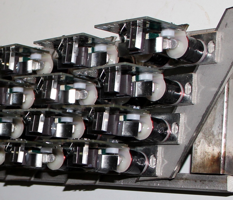
was fully up and running. Thus, first a prototype plucker was made using a solenoid
assembly from Syndyne: These
components are normally used as register knobs on pipe organs with electromagnetic
registration. We contacted the factory in order to obtain these components with
a straight anchor, as this would be much easier to attach the plectra. If we
use four rows of pluckers, and using a somewhat weird order of strings it appeared
possible to design the zither with a string distance of 15 mm. So for a 3 octave
instrument, the width could be limited to ca. 60 cm. We made a plucker assembly
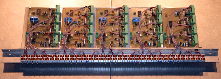
for a maximum of 38 strings, welded from stainless steel. The electronics require
twice as many pulse/hold circuits and thus we needed no less than six driver
boards and microprocessors. These boards are the same as the ones we developed
for <Qt>, <Bomi> and a few more robots where velocity control combined
with a hold function was needed. The boards have a maximum of 14 outputs each
and taking into acount that here we need two outputs for each string, we need
one board for every seven strings. The strange order of the strings was caused
by the design rule dictating the strings to be plucked at about 1/7th of their
lenght.
These
components are normally used as register knobs on pipe organs with electromagnetic
registration. We contacted the factory in order to obtain these components with
a straight anchor, as this would be much easier to attach the plectra. If we
use four rows of pluckers, and using a somewhat weird order of strings it appeared
possible to design the zither with a string distance of 15 mm. So for a 3 octave
instrument, the width could be limited to ca. 60 cm. We made a plucker assembly
for a maximum of 38 strings, welded from stainless steel. The electronics require
twice as many pulse/hold circuits and thus we needed no less than six driver
boards and microprocessors. These boards are the same as the ones we developed
for <Qt>, <Bomi> and a few more robots where velocity control combined
with a hold function was needed. The boards have a maximum of 14 outputs each
and taking into acount that here we need two outputs for each string, we need
one board for every seven strings. The strange order of the strings was caused
by the design rule dictating the strings to be plucked at about 1/7th of their
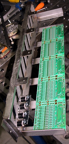
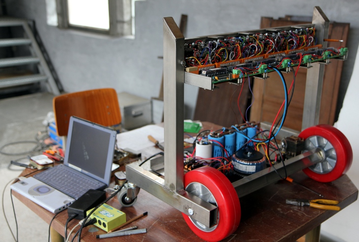
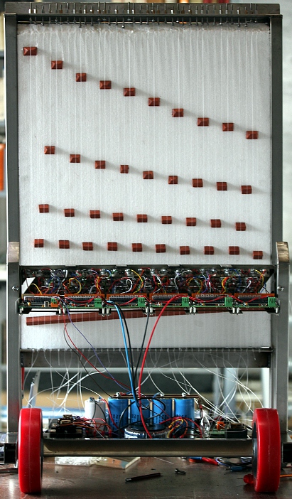
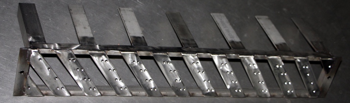
lenght. 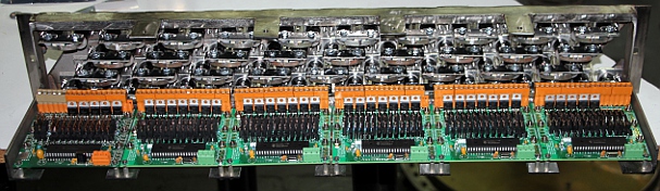 The picture
shows the plucker mechanism with associated electronics before wiring.
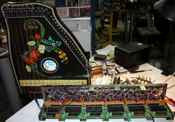
The picture
shows the plucker mechanism with associated electronics before wiring.
The circuit for the control of this prototype bidirectional solenoid assembly for each of the strings is given below:
As the pluckers at all times had to be in a deterministic position, it was impossible to implement a true power off for this robot. Only on cold boot, the pluckers will all go to a left position and thus pluck quite a few strings and sounding a cluster of notes. If we would implement a true power-off, this unwanted noise would be produced on any power on command. This implies that at any time when the robot is switched on, now allways 38 solenoids will be active in their position-hold state.
It took us more than two months to finish this prototype plucking mechanism.
As soon as this was ready we started experimenting and designing the actual
instrument in function of the possibilities of the mechanism. Parameters that
were fixed are the distance between strings (ca. 15mm), the shortest possible
string and therewith the highest possible note and last but not least, the maximum
thickness and force on the strings as this is limited by the maximum force the
pluckers can deliver. This drove our designs into the direction of using carbon
fiber or nylon strings as used on the qanun and using expanded polystyrene as
soundboard material. The <Rodo> robot, designed
earlier was our first attempt to use this material for a soundboard and was
proven to be pretty succesfull. Moreover, as the traditional qanun uses a bridge
resting at 4 to 5 points on stretched membranes (in this respect it shows some
acoustic similarity with the banjo), the idea to go for a styrofoam soundboard
is not at all alien to the instrument.
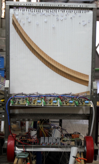
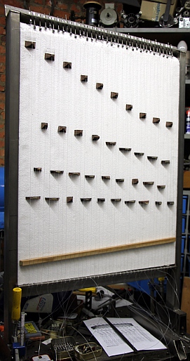
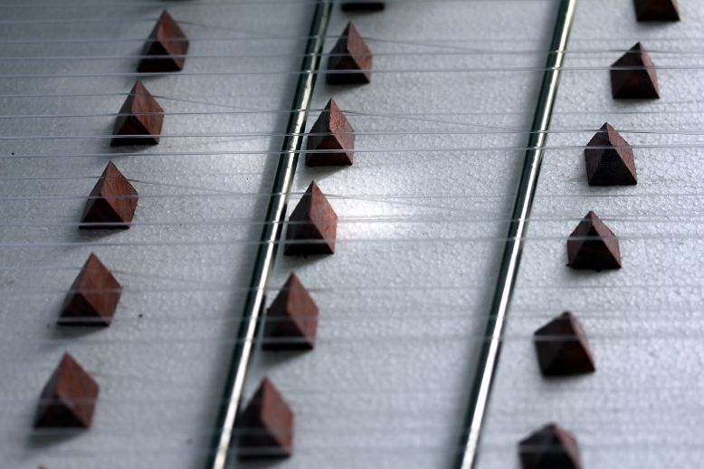
We forsake the use of double or triple strings for each note as we could not make this to work properly with our pivoting plucking mechanism. So we went for 38 single strings, however, tuned chromatically. (Qanuns have a diatonic tuning). For the tuning mechanism, after long experiments using mandolin tuning pegs in rows of four which came out to be unworkable, we designed a simple yet very effective mechanism. The advantage of our mechanism is that the strings are tensioned by pulling only and thus we can avoid any torsional forces in the strings as would have been the case if we rolled them on a cylinder as usually done. Another advantage of our mechanism is that close spacing of the pegs is easy to achieve. So, all tuning pegs could be arranged in a single row. Here is a picture of the prototype of the mechanism:
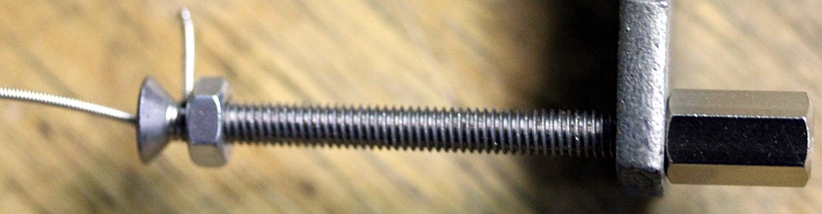
Users have to be carefull in tensioning the small M4 nut, if the tension is too high the string will be cut off! Tension should be just such as to prevent the string from sliding out. As an alternative to using the M4 nut, one can also make a knot around the tuning peg. This mechanism makes it perfectly possible to implement mandalar, by inserting small fork inserts between the long hexagonal tuning nut and the holder plate. However, we did not consider automation of such devices in this robot, mainly because it would make the whole construction way to heavy.
<Zi> being a string instrument, it will be clear that it cannot be used
without proper maintenance. Not only users will have to tune the instrument
properly, but also the bridges and the plectrums may need regular attention.
This is because in tuning, the bridges may move slightly and may cause the plectrums
to get out of adjustment. Bowed string instrument players will certainly be
familiar with this problem. The need for regular tuning arises from the use
of nylon strings. Had we used steel, the tuning would be a lot more stable,
but the tone quality would be far off the gentle qanun sound we had in mind
in the design.
The original string order and lay out looked like: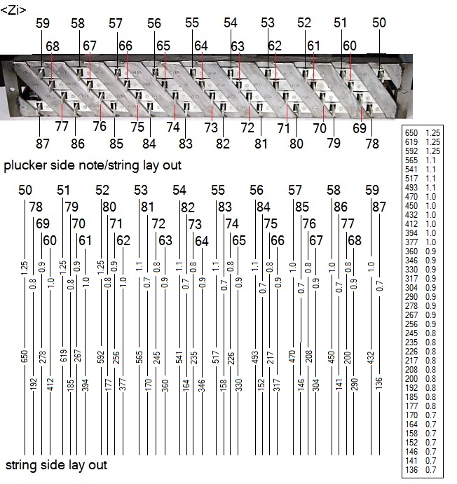 The string gages used as well as the sounding string lenghts are given in the
table.
The string gages used as well as the sounding string lenghts are given in the
table.
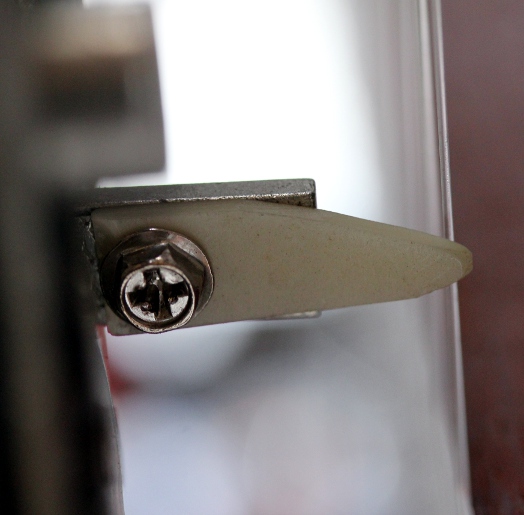
After many months of experimenting and trying to get the plectrums adjusted properly, we had to confess that the design of the plucker mechanism was a complete failure. We gave it up altogether and decided to design a second prototype. This time using longitudinal bidirectional solenoids with permanent magnets. These solenoids are stable in either of their end positions and they only require a pulse of changing polarity to make them change position. As this type of solenoid could not be obtained with an anti-rotation shaft, we decided to design round plectra with a 2 mm central hole for plucking the strings. The plectra are mounted on the shafts with two stainless steel M2 nuts.
Not only the plucker assembly had to be completely build again and redesigned, but also the electronics, including the power supply. This type of solenoid requires pulses of alternating polarity, thus requiring H-bridges to drive them. We used an old and proven H-bridge in IC form, the L298N. With a single 18F2525 microprocessor chip, we can steer a group of 8 solenoids. Here is the circuit:
 Five
of these boards are required for the complete qanun. The power requirements
are a lot more relaxed as compared to the first prototype design. This mainly
because of the pulse-only operation of the solenoids. However, these solenoids
having a DC resistance of only 4.2 Ohms, draw a pulse current of 2.8A each,
which is at the limit of what the L298 drivers can cope with. The data sheet
specifies a maximum of 3A, non repetitive pulse. The pulses being limited to
maximum 50ms with a 50% duty cycle relaxes the limits though. Unfortunately
there is as yet no integrated mosfet H-bridge on the market with a wider range.
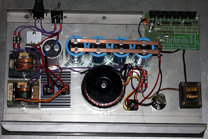
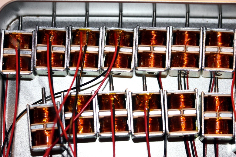
As to the power supply, a 12V / 500VA transformer and some parallelled LT1024-12V
regulators seemed adequate. Here is a picture of these solenoids:
Five
of these boards are required for the complete qanun. The power requirements
are a lot more relaxed as compared to the first prototype design. This mainly
because of the pulse-only operation of the solenoids. However, these solenoids
having a DC resistance of only 4.2 Ohms, draw a pulse current of 2.8A each,
which is at the limit of what the L298 drivers can cope with. The data sheet
specifies a maximum of 3A, non repetitive pulse. The pulses being limited to
maximum 50ms with a 50% duty cycle relaxes the limits though. Unfortunately
there is as yet no integrated mosfet H-bridge on the market with a wider range.
As to the power supply, a 12V / 500VA transformer and some parallelled LT1024-12V
regulators seemed adequate. Here is a picture of these solenoids: 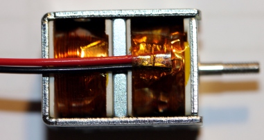
 This is the ambitus for the instrument when using a complete set of Qanun strings.
This also is the ambitus as implemented in MIDI.
This is the ambitus for the instrument when using a complete set of Qanun strings.
This also is the ambitus as implemented in MIDI.
However, this ambitus was at the original base of our design:  To reach this ambitus, guitar strings can be used. Obviously, if other strings
are used, other tunings are certainly possible. The instrument would than behave
as a transposing instrument and should be treated accordingly. The lowest note
in the original design (40), low E corresponds to the lowest note on the guitar
and will apply if the instrument is strung with guitar strings. As to
the Qanun, there is no real standard for the ambitus of the traditional Qanun,
although midi 50 (D) to 93 (a''), diatonic, is commonly found in Turkey.
To reach this ambitus, guitar strings can be used. Obviously, if other strings
are used, other tunings are certainly possible. The instrument would than behave
as a transposing instrument and should be treated accordingly. The lowest note
in the original design (40), low E corresponds to the lowest note on the guitar
and will apply if the instrument is strung with guitar strings. As to
the Qanun, there is no real standard for the ambitus of the traditional Qanun,
although midi 50 (D) to 93 (a''), diatonic, is commonly found in Turkey.
Midi channel: fixed to 4 (counting 0-15).
Note Off: Implemented for all notes in the range. Note Off does not reset the
repetition rate.
Note On: Implemented for notes in the range. Velo-byte is used for the striking force. The range is rather limited. The lights are also mapped on notes, but make use of a range outside the normal range of the zither.They are mapped on notes 120,121.
Key pressure: can be used to let notes repeat automatically. The pressure value
sets the repeat frequency. The command can be sent even prior to note-on commands.
The value send will be preserved until reset with a key pressure command for
the corresponding note with value zero. Controller 30 will override individual
key pressure commands.troller 20: Sets the tuning of the
instrument. The range is 33 to 52. The default is 50.
Controller 30: Can be used to set the repeat frequency of all notes to one and
the same value. By default this controller is zero.
Controller 66: Robot on/off switch. Sending a power off command (Ctrl 66 set
to 0) will cause a reset of all controllers to their default start up value.
Also settings for note repetition (key pressure commands) will be reset.
Controller 127: Sending this controller will reset all pluckers to an inward position. A power off command will be performed as well, thus causing a complete reset. The command takes some 10ms and users should make sure they do not send any other midi commands to the robot during this time interval. The command should not be used in midi sequences. Also, be warned that this command likely will pluck a lot of strings, as all pluckers in an outward position on entry, will be retracted to an inward position and thus the corresponding strings will be plucked. On a cold boot of the robot, this command is issued automatically.
Technical specifications:
Design and construction: dr.Godfried-Willem Raes
Collaborators on the construction of this robot:
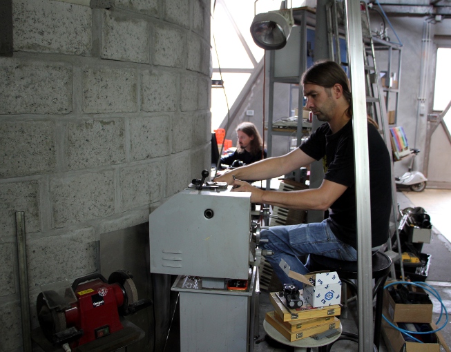
Pictures taken during the construction in our workshop (in chronological order):


| Back to Main Logos page:index.html | To Godfried-Willem Raes personal home page... | To Instrument catalogue |  |
Construction & Research Diary:
This is a modification of an August Laukhuff part used for registration knobs
on pipe-organs (Catalogue nr. 3 002 00). The original manufacturer appeared
to be Syndyne, and after checking their
catalogue it became apparent that we could also get these parts without
an angled anchor. We ought to proceed a bit faster with this design as we
are urged to do so by 'De Centrale', who commissioned it for a collaborative
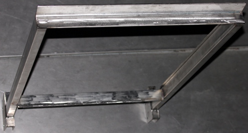
project with Adullah Abdulrasol.Welding
plan drawn out.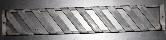
 . A box full of 6V bulbs with E14 fittings found on a street flea market here
in Ghent.
. A box full of 6V bulbs with E14 fittings found on a street flea market here
in Ghent.
 With
such tuning pegs, it would be imaginable to give the instruments two strings
for each note, as space requirements are really minimal. Another consequence
of using such tuning pegs is that it will lead to a pure rectangular soundboard
and instrument instead of the usual trapezoidal shape. It is mandatory that
the tuning pegs are fully in line with the strings. Giving the upper part
a staircase shape would be possible but involves a lot of welding and cutting
work.
With
such tuning pegs, it would be imaginable to give the instruments two strings
for each note, as space requirements are really minimal. Another consequence
of using such tuning pegs is that it will lead to a pure rectangular soundboard
and instrument instead of the usual trapezoidal shape. It is mandatory that
the tuning pegs are fully in line with the strings. Giving the upper part
a staircase shape would be possible but involves a lot of welding and cutting
work. This will be mounted on the bottom plate, 500 mm wide.
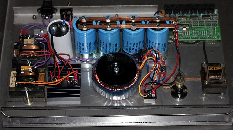
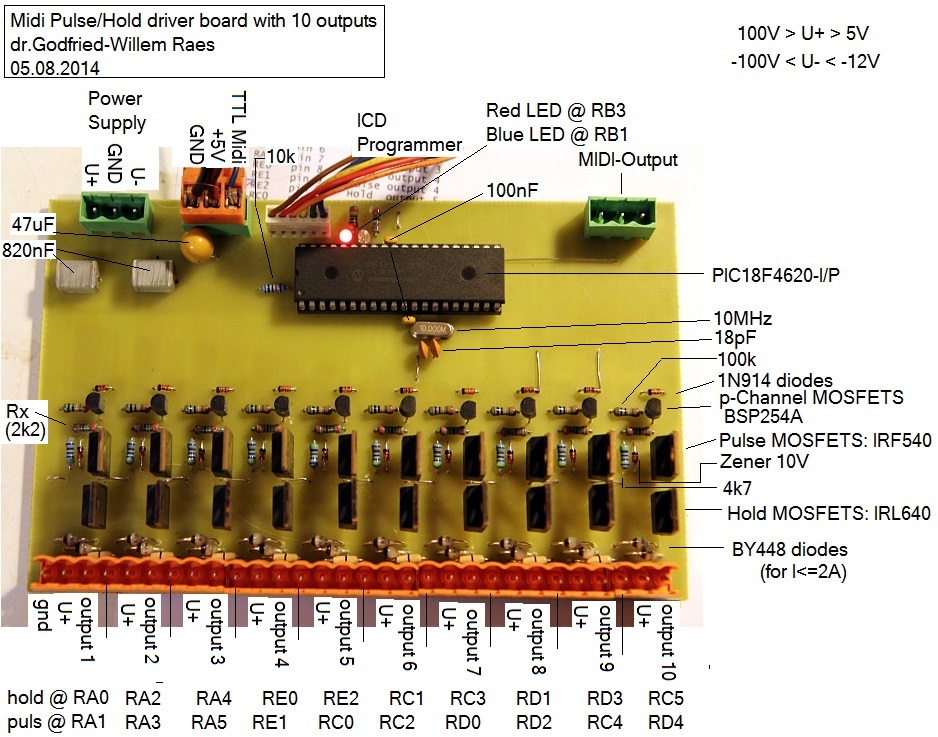
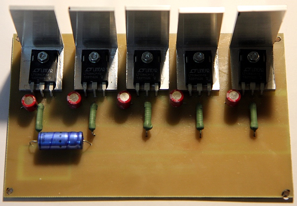
 This design should be reduced to 50% for production on a PC board. The diodes
used are U12C020A types: dual diodes in TO220 housing with a common anode.
Here is their data
sheet. The hold-mosfets are IRL640 and the velo mosfets IRF540. Note that
we produced these boards only for research reasons, not withstanding that
they may replace existing designs at some point.
This design should be reduced to 50% for production on a PC board. The diodes
used are U12C020A types: dual diodes in TO220 housing with a common anode.
Here is their data
sheet. The hold-mosfets are IRL640 and the velo mosfets IRF540. Note that
we produced these boards only for research reasons, not withstanding that
they may replace existing designs at some point.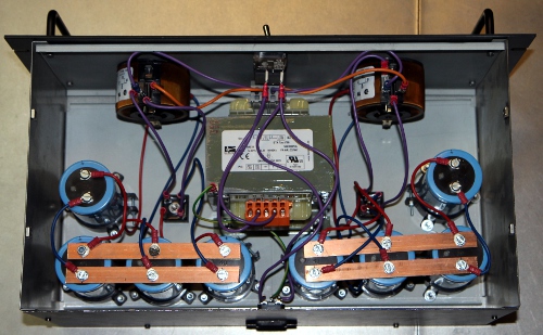 The 'harp' will be constructed such that it is a detachable and exchangeabe
part. This makes is possible to fit a harp with twice as long strings and
thus sounding an octave lower, or exchanging it for one with steel strings...
Anyhow we will start-off by designing and making a 'harp' of the smallest
possible sizing: longest string = 650 mm (sounding length).
The 'harp' will be constructed such that it is a detachable and exchangeabe
part. This makes is possible to fit a harp with twice as long strings and
thus sounding an octave lower, or exchanging it for one with steel strings...
Anyhow we will start-off by designing and making a 'harp' of the smallest
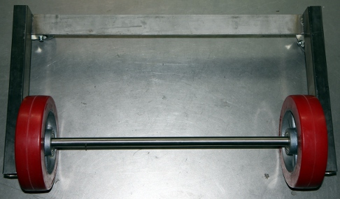
possible sizing: longest string = 650 mm (sounding length).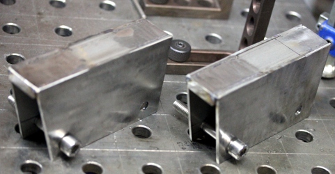 These must allow for a 20 mm slide to make adjustment of the strings with
the pluckers easier.
These must allow for a 20 mm slide to make adjustment of the strings with
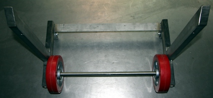
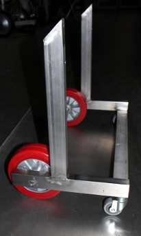
the pluckers easier. 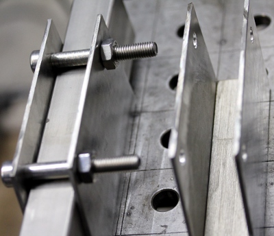 Big
mistake: we welded one of these feet in the wrong direction... we will have
to saw it off and start again...Mounting
test. We may need to add M10 setscrews on the 10 mm thick base plate of the
feet. First cut out of a sound board in expanded polystyrene. First experiments
with strings, using stranded beading wire. This sounds very good, a bit banjo
like.
Big
mistake: we welded one of these feet in the wrong direction... we will have
to saw it off and start again...Mounting
test. We may need to add M10 setscrews on the 10 mm thick base plate of the
feet. First cut out of a sound board in expanded polystyrene. First experiments
with strings, using stranded beading wire. This sounds very good, a bit banjo
like.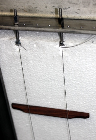 Although we will not use this as string material, this stranded beading wire
really sounds excellent. Here is a picture of the rolls on which it is sold:
Although we will not use this as string material, this stranded beading wire
really sounds excellent. Here is a picture of the rolls on which it is sold: Mattias Parent called in to help us out removing and replacing the strings.
More tuning pegs made
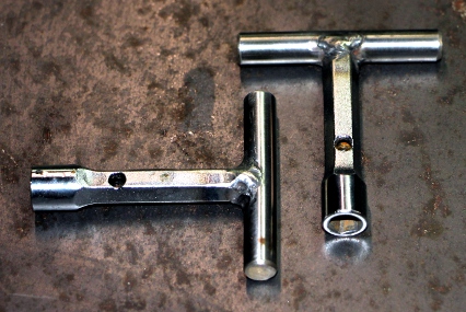
on the lathe. By the end of the day, all strings mounted. Two
tuning key made, starting from Beta tubular keys 6/7mm. These had to be hollowed
out with a 4 mm hole, at least 50 mm deep. Left
to be done: definitive bridges, construction, placement, adjustment. On the
picture, our experiments with different shapes and models of bridges can be
seen. Here is a detail of the tuning pegs:
Mattias Parent called in to help us out removing and replacing the strings.
More tuning pegs made
on the lathe. By the end of the day, all strings mounted. Two
tuning key made, starting from Beta tubular keys 6/7mm. These had to be hollowed
out with a 4 mm hole, at least 50 mm deep. Left
to be done: definitive bridges, construction, placement, adjustment. On the
picture, our experiments with different shapes and models of bridges can be
seen. Here is a detail of the tuning pegs: And this shows the knotting of the strings and the lower bridge:
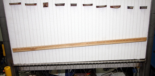
 As the polarity of the solenoids needs to be reversed after each stroke, we
need H-bridge drivers. The old and proven L298N came to rescue here. The big
advantage of this approach is that power consumption is minimal, as no hold
current is needed anymore. However, the current for each movement is 3A! Here
is a 200% PCB for the above circuit:
As the polarity of the solenoids needs to be reversed after each stroke, we
need H-bridge drivers. The old and proven L298N came to rescue here. The big
advantage of this approach is that power consumption is minimal, as no hold
current is needed anymore. However, the current for each movement is 3A! Here
is a 200% PCB for the above circuit:  For
the solenoids we bought to be tested, we need insulating washers with a hole
of 2 mm and an outer diameter of 10 mm. Thickness around 0.5mm. This needs
some hunting, unless we can make them ourselves on the lathe.
For
the solenoids we bought to be tested, we need insulating washers with a hole
of 2 mm and an outer diameter of 10 mm. Thickness around 0.5mm. This needs
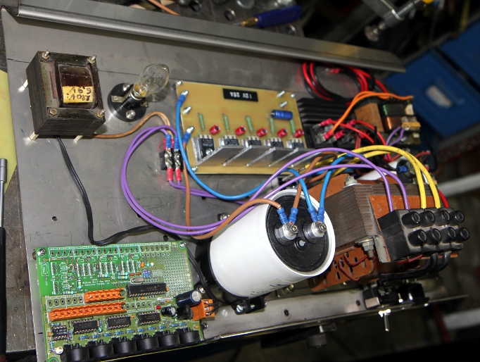
some hunting, unless we can make them ourselves on the lathe. The 12V transformer is clearly overdimensioned (200VA would have reached out)
but we simply had it at hand and thus decided to use it. PCB designed for
the five LT1084 regulators. The heat sinks are underdimensioned but that should
not be a problem as the supply needs only to be rated for momentary peak currents.
The 12V transformer is clearly overdimensioned (200VA would have reached out)
but we simply had it at hand and thus decided to use it. PCB designed for
the five LT1084 regulators. The heat sinks are underdimensioned but that should
not be a problem as the supply needs only to be rated for momentary peak currents.
 The PCB here is
at 200% and should be reduced to 50% before printing and exposing.
Drilling of the holes in the four to be done solenoid driver boards. Board
2 and soldered.
The PCB here is
at 200% and should be reduced to 50% before printing and exposing.
Drilling of the holes in the four to be done solenoid driver boards. Board
2 and soldered.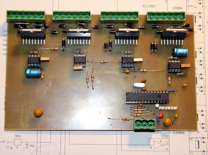
 and the one for
underneath:
and the one for
underneath: 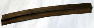
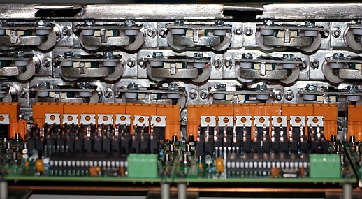
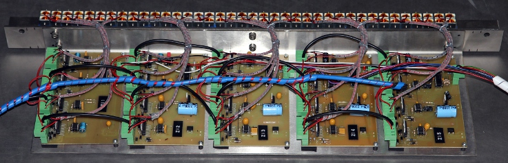
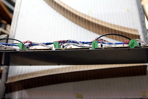
 All wiring done... The re-assembly on the chassis can start.
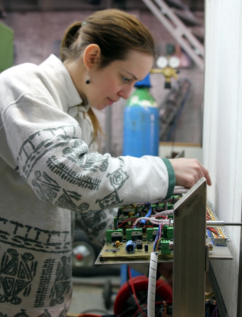 Looks
like we will have to order some spare 0.8 mm diameter Qanun string material.
Looks
like we will have to order some spare 0.8 mm diameter Qanun string material. The
thread for mounting the solenoids is M10x1 (metric extra fine).
The
thread for mounting the solenoids is M10x1 (metric extra fine).
TO DO:
| (Terug) naar logos-projekten: | Terug naar Logos' index-pagina: | Naar Godfried-Willem Raes personal homepage... | Naar katalogus instrumenten | |
M&M orkest |
Last update: 2026-02-08 by Godfried-Willem Raes
Circuit details solenoid driver boards:
The string lengths are calculated and the string gages follow those of
classical Qanun strings. We used a complete set for a 26 note diatonic Qanun
(Dupont Kanun Teli), strings from Turkey. The tables below give the speaking
lengths of the strings.
Board 1: notes 50 - 57
| string nr | 6-pole Weidmueller connector pins |
MIDI mapping |
PIC dir pin | PIC pulse pin (enable) | string lenght (mm) | string diameter |
| 1 |
A: 1,2 |
50 | RA0 | RA2 | 650 | 1.25 |
| 2 |
A: 5,6 |
51 | RA1 | RA3 | 620 | 1.25 |
| 3 |
B: 1,2 |
52 | RA4 | RC0 | 594 | 1.25 |
| 4 |
B: 5,6 |
53 | RA5 | RC1 | 571 | 1.10 |
| 5 |
C: 1,2 |
54 | RC2 | RC4 | 545 | 1.10 |
| 6 |
C: 5,6 |
55 | RC3 | RC5 | 518 | 1.10 |
| 7 |
D: 1,2 |
56 | RB0 | RB2 | 498 | 1.00 |
| 8 |
D: 5,6 |
57 | RB1 | RB3 | 476 | 1.00 |
| string nr | 6-pole Weidmueller connector pins |
MIDI mapping |
PIC dir pin | PIC pulse pin (enable) | string lenght (mm) | string diameter |
| 9 |
A: 1,2 |
58 | RA0 | RA2 | 457 | 1.00 |
| 10 |
A: 5,6 |
59 | RA1 | RA3 | 437 | 1.00 |
| 11 |
B: 1,2 |
60 | RA4 | RC0 | 419 | 1.00 |
| 12 |
B: 5,6 |
61 | RA5 | RC1 | 401 | 1.00 |
| 13 |
C: 1,2 |
62 | RC2 | RC4 | 384 | 1.00 |
| 14 |
C: 5,6 |
63 | RC3 | RC5 | 368 | 0.90 |
| 15 |
D: 1,2 |
64 | RB0 | RB2 | 353 | 0.90 |
| 16 |
D: 5,6 |
65 | RB1 | RB3 | 339 | 0.90 |
Board 3: notes 66 - 73
| string nr | 6-pole Weidmueller connector pins |
MIDI mapping |
PIC dir pin | PIC pulse pin (enable) | string lenght (mm) | string diameter |
| 17 |
A: 1,2 |
66 | RA0 | RA2 | 324 | 0.90 |
| 18 |
A: 5,6 |
67 | RA1 | RA3 | 310 | 0.90 |
| 19 |
B: 1,2 |
68 | RA4 | RC0 | 298 | 0.90 |
| 20 |
B: 5,6 |
69 | RA5 | RC1 | 287 | 0.90 |
| 21 |
C: 1,2 |
70 | RC2 | RC4 | 275 | 0.90 |
| 22 |
C: 5,6 |
71 | RC3 | RC5 | 264 | 0.90 |
| 23 |
D: 1,2 |
72 | RB0 | RB2 | 254 | 0.80 |
| 24 |
D: 5,6 |
73 | RB1 | RB3 | 244 | 0.80 |
| string nr | 6-pole Weidmueller connector pins |
MIDI mapping |
PIC dir pin | PIC pulse pin (enable) | string lenght (mm) | string diameter |
| 25 |
A: 1,2 |
74 | RA0 | RA2 | 235 | 0.80 |
| 26 |
A: 5,6 |
75 | RA1 | RA3 | 226 | 0.80 |
| 27 |
B: 1,2 |
76 | RA4 | RC0 | 217 | 0.80 |
| 28 |
B: 5,6 |
77 | RA5 | RC1 | 209 | 0.80 |
| 29 |
C: 1,2 |
78 | RC2 | RC4 | 201 | 0.80 |
| 30 |
C: 5,6 |
79 | RC3 | RC5 | 194 | 0.80 |
| 31 |
D: 1,2 |
80 | RB0 | RB2 | 187 | 0.80 |
| 32 |
D: 5,6 |
81 | RB1 | RB3 | 180 | 0.70 |
| string nr | 6-pole Weidmueller connector pins |
MIDI mapping |
PIC dir pin | PIC pulse pin (enable) | string lenght (mm) | string diameter |
| 33 |
A: 1,2 |
82 | RA0 | RA2 | 174 | 0.70 |
| 34 |
A: 5,6 |
83 | RA1 | RA3 | 168 | 0.70 |
| 35 |
B: 1,2 |
84 | RA4 | RC0 | 162 | 0.70 |
| 36 |
B: 5,6 |
85 | RA5 | RC1 | 156 | 0.70 |
| 37 |
C: 1,2 |
86 | RC2 | RC4 | 151 | 0.70 |
| 38 |
C: 5,6 |
87 | RC3 | RC5 | 146 | 0.70 |
| - |
D: 1,2 |
nc | RB0 | RB2 | - | - |
| - |
D: 5,6 |
nc | RB1 | RB3 | - | - |
Schematic:
Tuning mechanism:
Mandalar
can be mounted as an option. Moving the bridges is also possible to obtain
microtonal scales. When changing a string, to not overtighten the small
M4 nut holding the string on the threaded tuning pegs. If too much force
is given here, the string will be cut off! In tuning, hold the threaded
bolt part such that it does not twist when rotating the tuning nuts.Plucking birectional solenoid or linear motor assemblies:
References:
Linear Technologies: LT1083, LT1084,
LT1085 Low dropout positive fixed voltage regulators
RAES, Godfried-Willem, "Expression control in musical automates", 1977/2026
ROSSING, Thomas.D (editor), "The Science of String Instruments" , ed: Springer NY, Stanford CCRMA, 2010 ISBN 978-1-4419-7109-8
SMIT, Thorsten a.o.,
'A highly accurate plucking mechanism for acoustical measurements of stringed
instruments', in: Journal of the Acoustical Society of America, EL223,
may 2010.
STMicroelectronics: Data sheet for the L298 dual full bridge driver
STMicroelectronics: L6201-L6202-L6203 DMOS dual full bridge driver
Wikipedia entry on the Qanun.
Archival
Rejected version 1.0 documentation:
Power supplies:
Circuit details solenoid driver boards:
The string lengths are calculated and the string gages follow those of classical
Qanun strings. We used a complete set for a 26 note diatonic Qanun (Dupont Kanun
Teli), strings from Turkey.
Board 1:
| string nr | board output | connector pin | mapping | remarks | PIC pulse pin | PIC hold pin | string lenght (mm) | string diameter |
| - | 1 | 2 | note 120 | hold only - lite | 4 = RA1 | 3 = RA2 | ||
| - | 2 | 3 | note 121 | hold only - lite | 2 = RA3 | 5 = RA0 | ||
| - | 3 | 4 | nc | nc (broken) | 6 = RA5 | 7 = RA4 (*) | ||
| - | 4 | 5 | nc | nc | 9 = RE1 | 8 = RE0 | ||
| 1 | 5 | 7 | 50 | left | 37 = RB4 | 10 = RE2 | 650 | 1.25 |
| 1 | 6 | 8 | right | 35 = RB2 | 36 = RB3 | |||
| 2 | 7 | 9 | 78 | left | 33 = RB0 | 34 = RB1 | 201 | 0.80 |
| 2 | 8 | 10 | right | 29 = RD6 | 30 = RD7 | |||
| 3 | 9 | 12 | 69 | left | 27 = RD4 | 28 = RD5 | 287 | 0.90 |
| 3 | 10 | 13 | right | 23 = RC4 | 24 = RC5 | |||
| 4 | 11 | 14 | 60 | left | 21 = RD2 | 22 = RD3 | 419 | 1.00 |
| 4 | 12 | 15 | right | 16 = RC1 | 15 = RC0 | |||
| 5 | 13 | 17 | 51 | left | 18 = RC3 | 17 = RC2 | 620 | 1.25 |
| 5 | 14 | 18 | right | 20 = RD1 | 19 = RD0 |
This board uses BYV27 diodes in the hold-circuit. On the other 5 boards we used MUR4100 types. The double diodes are invariably BYV32 types. These are only mounted on outputs meant to switch inductive loads. The P-channel Mosfets are BSP254A types and the power Mosfets all IRL640. On this board pin RA5 is programmed to be used as a loopspeed measurement output. The pin can be accessed on the gate connection of the hold mosfet, not mounted on the board. Weidmueller connector pins 1,6,11,16, 19 are connected to the positive hold voltage on all boards (+6 V).
The source code for the 18F4620 processor on this board can be downloaded here.
Board 2:
| string nr | board output | connector pin | mapping | remarks | PIC hold pin | PIC pulse pin | string length (mm) |
string diameter |
| 6 | 1 | 2 | 79 | left | 4 = RA2 | 3 = RA1 | 194 | 0.80 |
| 6 | 2 | 3 | right | 2 = RA0 | 5 = RA3 | |||
| 7 | 3 | 4 | 70 | left | 6 = RA4 | 7 = RA5 | 275 | 0.90 |
| 7 | 4 | 5 | right | 8 = RE0 | 9 = RE1 | |||
| 8 | 5 | 7 | 61 | left | 10 = RE2 | 37 = RB4 | 401 | 1.00 |
| 8 | 6 | 8 | right | 36 = RB3 | 35 = RB2 | |||
| 9 | 7 | 9 | 52 | left | 34 = RB1 | 33 = RB0 | 594 | 1.25 |
| 9 | 8 | 10 | right | 30 = RD7 | 29 = RD6 | |||
| 10 | 9 | 12 | 80 | left | 28 = RD5 | 27 = RD4 | 187 | 0.80 |
| 10 | 10 | 13 | right | 24 = RC5 | 23 = RC4 | |||
| 11 | 11 | 14 | 71 | left | 22 = RD3 | 21 = RD2 | 264 | 0.90 |
| 11 | 12 | 15 | right | 15 = RC0 | 16 = RC1 | |||
| 12 | 13 | 17 | 62 | left | 17 = RC2 | 18 = RC3 | 384 | 1.00 |
| 12 | 14 | 18 | right | 19 = RD0 | 20 = RD1 |
The source code for the 18F4620 processor on this board can be downloaded here.
Board 3:
| string nr | board output | connector pin | mapping | remarks | PIC hold pin | PIC pulse pin | string length (mm) | string diameter |
| 13 | 1 | 2 | 53 | left | 4 = RA2 | 3 = RA1 | 571 | 1.10 |
| 13 | 2 | 3 | right | 2 = RA0 | 5 = RA3 | |||
| 14 | 3 | 4 | 81 | left | 6 = RA4 | 7 = RA5 | 180 | 0.70 |
| 14 | 4 | 5 | right | 8 = RE0 | 9 = RE1 | |||
| 15 | 5 | 7 | 72 | left | 10 = RE2 | 37 = RB4 | 254 | 0.80 |
| 15 | 6 | 8 | right | 36 = RB3 | 35 = RB2 | |||
| 16 | 7 | 9 | 63 | left | 34 = RB1 | 33 = RB0 | 368 | 0.90 |
| 16 | 8 | 10 | right | 30 = RD7 | 29 = RD6 | |||
| 17 | 9 | 12 | 54 | left | 28 = RD5 | 27 = RD4 | 545 | 1.10 |
| 17 | 10 | 13 | right | 24 = RC5 | 23 = RC4 | |||
| 18 | 11 | 14 | 82 | left | 22 = RD3 | 21 = RD2 | 174 | 0.70 |
| 18 | 12 | 15 | right | 15 = RC0 | 16 = RC1 | |||
| 19 | 13 | 17 | 73 | left | 17 = RC2 | 18 = RC3 | 244 | 0.80 |
| 19 | 14 | 18 | right | 19 = RD0 | 20 = RD1 |
The source code for the 18F4620 processor on this board can be downloaded here.
Board 4:
| string nr | board output | connector pin | mapping | remarks | PIC hold pin | PIC pulse pin | string length (mm) | string diameter |
| 20 | 1 | 2 | 64 | left | 4 = RA2 | 3 = RA1 | 353 | 0.90 |
| 20 | 2 | 3 | right | 2 = RA0 | 5 = RA3 | |||
| 21 | 3 | 4 | 55 | left | 6 = RA4 | 7 = RA5 | 518 | 1.10 |
| 21 | 4 | 5 | right | 8 = RE0 | 9 = RE1 | |||
| 22 | 5 | 7 | 83 | left | 10 = RE2 | 37 = RB4 | 168 | 0.70 |
| 22 | 6 | 8 | right | 36 = RB3 | 35 = RB2 | |||
| 23 | 7 | 9 | 74 | left | 34 = RB1 | 33 = RB0 | 235 | 0.80 |
| 23 | 8 | 10 | right | 30 = RD7 | 29 = RD6 | |||
| 24 | 9 | 12 | 65 | left | 28 = RD5 | 27 = RD4 | 339 | 0.90 |
| 24 | 10 | 13 | right | 24 = RC5 | 23 = RC4 | |||
| 25 | 11 | 14 | 56 | left | 22 = RD3 | 21 = RD2 | 498 | 1.00 |
| 25 | 12 | 15 | right | 15 = RC0 | 16 = RC1 | |||
| 26 | 13 | 17 | 84 | left | 17 = RC2 | 18 = RC3 | 162 | 0.70 |
| 26 | 14 | 18 | right | 19 = RD0 | 20 = RD1 |
The source code for the 18F4620 processor on this board can be downloaded here.
Board 5:
| string nr | board output | connector pin | mapping | remarks | PIC hold pin | PIC pulse pin | string length (mm) | string diameter |
| 27 | 1 | 2 | 75 | left | 4 = RA2 | 3 = RA1 | 226 | 0.80 |
| 27 | 2 | 3 | right | 2 = RA0 | 5 = RA3 | |||
| 28 | 3 | 4 | 66 | left | 6 = RA4 | 7 = RA5 | 324 | 0.90 |
| 28 | 4 | 5 | right | 8 = RE0 | 9 = RE1 | |||
| 29 | 5 | 7 | 57 | left | 10 = RE2 | 37 = RB4 | 476 | 1.00 |
| 29 | 6 | 8 | right | 36 = RB3 | 35 = RB2 | |||
| 30 | 7 | 9 | 85 | left | 34 = RB1 | 33 = RB0 | 156 | 0.70 |
| 30 | 8 | 10 | right | 30 = RD7 | 29 = RD6 | |||
| 31 | 9 | 12 | 76 | left | 28 = RD5 | 27 = RD4 | 217 | 0.80 |
| 31 | 10 | 13 | right | 24 = RC5 | 23 = RC4 | |||
| 32 | 11 | 14 | 67 | left | 22 = RD3 | 21 = RD2 | 310 | 0.90 |
| 32 | 12 | 15 | right | 15 = RC0 | 16 = RC1 | |||
| 33 | 13 | 17 | 58 | left | 17 = RC2 | 18 = RC3 | 457 | 1.00 |
| 33 | 14 | 18 | right | 19 = RD0 | 20 = RD1 |
The source code for the 18F4620 processor on this board can be downloaded here.
Board 6:
| string nr | board output | connector pin | mapping | remarks | PIC hold pin | PIC pulse pin | string length | string diameter |
| 34 | 1 | 2 | 86 | left | 4 = RA2 | 3 = RA1 | 151 | 0.70 |
| 34 | 2 | 3 | right | 2 = RA0 | 5 = RA3 | |||
| 35 | 3 | 4 | 77 | left | 6 = RA4 | 7 = RA5 | 209 | 0.80 |
| 35 | 4 | 5 | right | 8 = RE0 | 9 = RE1 | |||
| 36 | 5 | 7 | 68 | left | 10 = RE2 | 37 = RB4 | 298 | 0.90 |
| 36 | 6 | 8 | right | 36 = RB3 | 35 = RB2 | |||
| 37 | 7 | 9 | 59 | left | 34 = RB1 | 33 = RB0 | 437 | 1.00 |
| 37 | 8 | 10 | right | 30 = RD7 | 29 = RD6 | |||
| 38 | 9 | 12 | 87 | left | 28 = RD5 | 27 = RD4 | 146 | 0.70 |
| 38 | 10 | 13 | right | 24 = RC5 | 23 = RC4 | |||
| - | 11 | 14 | nc | nc | 22 = RD3 | 21 = RD2 | ||
| - | 12 | 15 | nc | nc | 15 = RC0 | 16 = RC1 | ||
| - | 13 | 17 | 122 | hold only - lite | 17 = RC2 | 18 = RC3 | ||
| - | 14 | 18 | 123 | hold only -lite | 19 = RD0 | 20 = RD1 |
The source code for the 18F4620 processor on this board can be downloaded here.
This board does not have the pulse Mosfets nor the double diodes in the four right-most outputs.
Schematic: 
Plucking birectional solenoid assemblies: