|

Research project on the development
of new tools for musical expression at the University College Ghent
School of Arts
|
|
<Rodo>
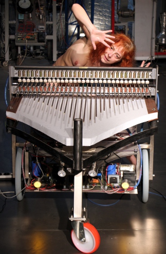
an automated and interactive set of bronze tines
Godfried-Willem RAES
2013 - 2017
|
<Rodo>
Rods clamped on one side and free to vibrate at the other side are the acoustical
base of quite many musical instruments and sound installations: reed organs,
mouth organs, bandoneon, music boxes with a comb, nail violin, toy piano, Fender-Rhodes
piano, Waterphones, Harry Bertoia's installations, African lamellophones, clock
gongs to name just a few. Two classes of instruments using this sound source
should be distinguished: instruments that only use the fundamental resonant
tone (reed organs, Fender-Rhodes, music boxes) and that are always considered
pitched instruments and at the other hand those that use the broad spectrum
of overtones these rods can generate, when tuned to very low fundamental resonant
frequencies (clocks, Waterphone, toy piano...). The fundamental resonant frequency
of these rods is inversely proportional to the square of the length of the rod:
 With: f= frequency in
Hz, L= length of the rod, k=diameter of the rod, Q= modulus of elasticity, r=
density of the material. (Olson, p.76)
The <Rodo> robot was designed to be either an extension or a generalization
of the toy piano robot <Toypi>. Just like in
the toy piano, the sounds all stem from massive rods clamped at one end in a
solid cast iron bar. We started the project, as the automation of the small
instrument was very successful and appeared to have many more sonic possibilities
than we grasped at the start. So we thought of rescaling the design such that
the range would extend much lower and the maximum sound level quite a bit higher.
At the same time, we aimed at making the instrument a lot more sturdy than the
toy instrument, that needed all too many repairs because the tines broke very
easily on very fast note-repetition rates. Also quite some new features were
added in this design: individual dampers, an e-drive mechanism and a set of
sensors to allow gesture interactive activation and playing modes.
We started off by doing experiments on different metals and alloys for the
tines: martensic stainless steel, hardened spring steel, brass, aluminum, phosfor-bronze,
aluminum-bronze. We even experimented with some non metals such as bamboo, glass,
carbon-fibre. Those experiments made us drop the nonmetals very fast as the
sound was too weak or the rods too fragile. Obviously the evaluation of sonic
quality has to remain a quite subjective issue, since there is no standard to
compare to as we are designing a new instrument. After all these experiments
were performed we decided to go for the aluminum-bronze alloy. These rods produce
a very rich tone, though not as brilliant and loud as spring steel rods. As
we couldn't get beryllium copper (after the properties, it ought to be the perfect
material here) nor phosphor bronze (CuSn8) ,we cannot judge on these promising
alloys. In the design of <Rodo> we took into account the possibility for
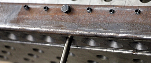
tuning and adaptation to different tuning systems. To allow this, set screws
are used to fix the vibrating length of the tone rods. This arrangement makes
it possible to exchange the rods for other sets, as long as the diameter is
8 mm. By default the tuning is chromatic, equal temperament. The electromagnetic
driver feature however, can work in different tuning systems, including just
intonation. Due to the high inharmonicity of vibrating bars clamped at one end,
it is perfectly possible to consider the instrument as 'non-pitched' in the
context of orchestra compositions conceived for our robots. In this respect,
the instrument would sound like a set of gongs.
The acoustics of rods clamped at one end, after the theory books (Rayleigh,V1,p.278;
Talukdar) allow us to predict the frequency of the overtones.
| f0 (fundamental) |
1 |
| f1 |
6.276 |
| f2 |
17.547 |
| f3 |
34.155 |
| f4 |
56.84 |
| f5 |
84.91 |
The literature on the subject doesn't give any values for higher overtones than
f5. Also, different authors do not seem to agree on the exact values of the factors.
The factors derived from theoretical calculus, generally simplify the problem
by neglecting the torsional forces occurring in vibrating rods, only considering
lateral vibration. So, these factors can only be used as guidelines and experiments
were necessary to obtain more exact results.
One would expect that the perceived pitch of a struck and clamped rod would
correspond to at least one of these overtones, however -at least for the rods
we selected- this is not the case. In the table below we give the measured frequencies
of a single bronze rod, 8 mm in diameter and cut to a length of 961 mm. (An
extra length of 20 mm serves for clamping and thus can be considered acoustically
dead). The perceived pitch of this bar was C#3 raised 20 cents (139.45 Hz),
yet this pitch was not found back under forced resonance conditions::
| |
measured |
calculated |
remarks |
| f0 |
5 Hz |
4.937 Hz |
=MM296, checked by comparison to a metronome set to MM150 |
| f1 |
30.86 Hz |
30.987 Hz |
almost unmeasurable |
| f2 |
86.19 Hz |
86,638 Hz |
|
| f3 |
168.64 Hz |
168.64 Hz |
reference tone used for best match with calculated spectrum |
| f4 |
280.47 Hz |
280.647 Hz |
this corresponds to the octave above the perceived pitch (139.45 Hz) |
| f5 |
416.00 Hz |
419.24 Hz |
|
| f6 |
581.66 Hz |
- |
|
| f7 |
773.50 Hz |
- |
|
| f8 |
986.80 Hz |
- |
|
| f9 |
1235.57 Hz |
- |
|
| f10 |
1807.5 Hz |
- |
|
| f11 |
2128.27 Hz |
- |
|
Measurements were performed under forced excitation using a transducer driven
by a Thurlby Thandar TG1006 DDS function generator with a 6 digit frequency
readout. Resonance's were determined by very slowly sweeping the sine wave frequency
and fine tuning to find the peeks in amplitude. When we tried to make the rod
resonate to the perceived pitch of 139.45 Hz, it clearly responded with the
pitch found in the table for f4. The conclusion is that our ear adds a 'missing
fundamental' here. This is not something novel, as similar phenomena have been
described with regard to the perceived pitches of tubular bells.
To conclude our measurements on the test rod, we tried to excite it with a
bow and could find all overtones from f2 to f9 back, be it sometimes after quite
some attempts as it seems difficult to predict the pitch one will get when bowing.
Starting from the measurements and experimental data obtained, we designed
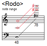
a small computer program to calculate all 31 rods based on a perceived pitch
range from C3 (midi note 48) to F#5 (midi note 78) for equal temperament and
a basic tuning to A=440 Hz..
| midi
note |
frequency |
rod length |
id. with
clamp |
f0 |
note0 |
f1 |
note1 |
f2 |
note2 |
f3 |
note3 |
f4 |
note4 |
f5 |
note5 |
| 48 |
130.8 |
989.16 |
1009.2 |
4.603 |
-9.946 |
28.89 |
21.85 |
80.77 |
39.65 |
157.2 |
51.18 |
261.6 |
60 |
390.8 |
66.95 |
| 49 |
138.6 |
961 |
981 |
4.876 |
-8.946 |
30.6 |
22.85 |
85.57 |
40.65 |
166.6 |
52.18 |
277.2 |
61 |
414.1 |
67.95 |
| 50 |
146.8 |
933.64 |
953.64 |
5.166 |
-7.946 |
32.42 |
23.85 |
90.66 |
41.65 |
176.5 |
53.18 |
293.7 |
62 |
438.7 |
68.95 |
| 51 |
155.6 |
907.06 |
927.06 |
5.474 |
-6.946 |
34.35 |
24.85 |
96.05 |
42.65 |
187 |
54.18 |
311.1 |
63 |
464.8 |
69.95 |
| 52 |
164.8 |
881.24 |
901.24 |
5.799 |
-5.946 |
36.4 |
25.85 |
101.8 |
43.65 |
198.1 |
55.18 |
329.6 |
64 |
492.4 |
70.95 |
| 53 |
174.6 |
856.15 |
876.15 |
6.144 |
-4.946 |
38.56 |
26.85 |
107.8 |
44.65 |
209.8 |
56.18 |
349.2 |
65 |
521.7 |
71.95 |
| 54 |
185 |
831.78 |
851.78 |
6.509 |
-3.946 |
40.85 |
27.85 |
114.2 |
45.65 |
222.3 |
57.18 |
370 |
66 |
552.7 |
72.95 |
| 55 |
196 |
808.1 |
828.1 |
6.896 |
-2.946 |
43.28 |
28.85 |
121 |
46.65 |
235.5 |
58.18 |
392 |
67 |
585.6 |
73.95 |
| 56 |
207.6 |
785.1 |
805.1 |
7.306 |
-1.946 |
45.86 |
29.85 |
128.2 |
47.65 |
249.6 |
59.18 |
415.3 |
68 |
620.4 |
74.95 |
| 57 |
220 |
762.75 |
782.75 |
7.741 |
-0.946 |
48.58 |
30.85 |
135.8 |
48.65 |
264.4 |
60.18 |
440 |
69 |
657.3 |
75.95 |
| 58 |
233.1 |
741.03 |
761.03 |
8.201 |
0.054 |
51.47 |
31.85 |
143.9 |
49.65 |
280.1 |
61.18 |
466.2 |
70 |
696.4 |
76.95 |
| 59 |
246.9 |
719.94 |
739.94 |
8.689 |
1.054 |
54.53 |
32.85 |
152.5 |
50.65 |
296.8 |
62.18 |
493.9 |
71 |
737.8 |
77.95 |
| 60 |
261.6 |
699.44 |
719.44 |
9.206 |
2.054 |
57.77 |
33.85 |
161.5 |
51.65 |
314.4 |
63.18 |
523.2 |
72 |
781.6 |
78.95 |
| 61 |
277.2 |
679.53 |
699.53 |
9.753 |
3.054 |
61.21 |
34.85 |
171.1 |
52.65 |
333.1 |
64.18 |
554.4 |
73 |
828.1 |
79.95 |
| 62 |
293.7 |
660.18 |
680.18 |
10.33 |
4.054 |
64.85 |
35.85 |
181.3 |
53.65 |
352.9 |
65.18 |
587.3 |
74 |
877.4 |
80.95 |
| 63 |
311.1 |
641.39 |
661.39 |
10.95 |
5.054 |
68.71 |
36.85 |
192.1 |
54.65 |
373.9 |
66.18 |
622.2 |
75 |
929.5 |
81.95 |
| 64 |
329.6 |
623.13 |
643.13 |
11.6 |
6.054 |
72.79 |
37.85 |
203.5 |
55.65 |
396.1 |
67.18 |
659.2 |
76 |
984.8 |
82.95 |
| 65 |
349.2 |
605.39 |
625.39 |
12.29 |
7.054 |
77.12 |
38.85 |
215.6 |
56.65 |
419.7 |
68.18 |
698.4 |
77 |
1043 |
83.95 |
| 66 |
370 |
588.16 |
608.16 |
13.02 |
8.054 |
81.71 |
39.85 |
228.4 |
57.65 |
444.6 |
69.18 |
740 |
78 |
1105 |
84.95 |
| 67 |
392 |
571.41 |
591.41 |
13.79 |
9.054 |
86.56 |
40.85 |
242 |
58.65 |
471.1 |
70.18 |
784 |
79 |
1171 |
85.95 |
| 68 |
415.3 |
555.15 |
575.15 |
14.61 |
10.05 |
91.71 |
41.85 |
256.4 |
59.65 |
499.1 |
71.18 |
830.6 |
80 |
1241 |
86.95 |
| 69 |
440 |
539.34 |
559.34 |
15.48 |
11.05 |
97.16 |
42.85 |
271.7 |
60.65 |
528.8 |
72.18 |
880 |
81 |
1314 |
87.95 |
| 70 |
466.2 |
523.99 |
543.99 |
16.4 |
12.05 |
102.9 |
43.85 |
287.8 |
61.65 |
560.2 |
73.18 |
932.3 |
82 |
1393 |
88.95 |
| 71 |
493.9 |
509.07 |
529.07 |
17.38 |
13.05 |
109.1 |
44.85 |
304.9 |
62.65 |
593.5 |
74.18 |
987.8 |
83 |
1476 |
89.95 |
| 72 |
523.2 |
494.58 |
514.58 |
18.41 |
14.05 |
115.5 |
45.85 |
323.1 |
63.65 |
628.8 |
75.18 |
1046 |
84 |
1563 |
90.95 |
| 73 |
554.4 |
480.5 |
500.5 |
19.51 |
15.05 |
122.4 |
46.85 |
342.3 |
64.65 |
666.2 |
76.18 |
1109 |
85 |
1656 |
91.95 |
| 74 |
587.3 |
466.82 |
486.82 |
20.67 |
16.05 |
129.7 |
47.85 |
362.6 |
65.65 |
705.8 |
77.18 |
1175 |
86 |
1755 |
92.95 |
| 75 |
622.2 |
453.53 |
473.53 |
21.89 |
17.05 |
137.4 |
48.85 |
384.2 |
66.65 |
747.8 |
78.18 |
1244 |
87 |
1859 |
93.95 |
| 76 |
659.2 |
440.62 |
460.62 |
23.2 |
18.05 |
145.6 |
49.85 |
407 |
67.65 |
792.3 |
79.18 |
1318 |
88 |
1970 |
94.95 |
| 77 |
698.4 |
428.08 |
448.08 |
24.58 |
19.05 |
154.2 |
50.85 |
431.2 |
68.65 |
839.4 |
80.18 |
1397 |
89 |
2087 |
95.95 |
| 78 |
740 |
415.89 |
435.89 |
26.04 |
20.05 |
163.4 |
51.85 |
456.9 |
69.65 |
889.3 |
81.18 |
1480 |
90 |
2211 |
96.95 |
|
|
|
|
|
|
|
|
|
|
|
|
|
|
|
|
The negative fractional midi note numbers in the note0 column (giving the fundamental
frequency of the rods) are colored brown, as these cannot be properly expressed
in MIDI. Beyond that, it will be clear that they are absolutely inaudible. To
measure their frequency, a calibrated stroboscope can be used. The notes given
as overtones are notated as fractional midi, the integer part being the midi
note and the fractional part the fraction in cents. Note that the (nearly) fifth
intervals between the notes 4 and 5 are the cause of our perception of a missing
fundamental, heard as f4 / 2.
To strike the tines, we decided to use Kuhnke thrust type solenoids with conical
face armatures. Type HM157 has an armature weighting only 8 g. The nominal voltage
for 100% duty cycle is 24 V, but at that voltage the attack time is 34 ms for
a traject of 5 mm. The data sheet specifies:
| duty cycle |
power |
attack time |
force |
voltage |
| 100% |
2.8 W |
34 ms |
1 N |
24 V |
| 70% |
4.3 W |
|
1.5 N |
30 V |
| 45% |
6.5 W |
|
2 N |
36 V |
| 25% |
10 W |
|
2.5 N |
45 V |
| 15% |
18 W |
|
3 N |
60 V |
| 5% |
52 W |
8 ms |
5 N |
103 V |
The DC resistance of the coil is 206 Ohms. We decided to design the robot for
operation on 60 V and thus the duty cycle should be restricted to 15%. Thus
the maximum note repetition speed at full power should be brought down from
the theoretical maximum of 50 strokes a second to ca. 15 strokes a second. Power
supply requirements can now be derived from these data: we have 31 solenoids
and thus the required power becomes: 18 W * 31 * 0.15 = 84 W. In order to stay
on the safe side, a 48 V ac transformer rated at 100 VA should do the job. After
rectification and smoothing, this will give us a dc voltage of ca. 65 V without
load, going down to 48 V al full load. By raising the voltage, we can improve
the attack time considerably as shown, but one should keep in mind that the
fall back time is limited by the force of gravity. When we calculate this for
a fall trajectory of 5 mm ( t = SQR(0.005/4.9) we get 32 ms. Thus the fastest
full up-down cycle would take 40 ms, leading to a fastest possible repetition
speed of 25 Hz. However, in practice when driven much faster than these repetition
speeds, it still works fine but the anchors will not fully fall back between
strokes. As a consequence, the amplitude of the produced sound will decrease.
The mass of the longest tine being ca. 400 g entails that the striking force
for a good excitation ought to be between 0.39 N and 0.78 N. These values will
be reached with midi velocity values around 80.
An extra and new feature of the <Rodo> design, as compared to <Toypi>
is the electromagnetic feedback driver mechanism. To this end we mounted a powerful
(100 W) electromagnet very close (leaving just an air gap less than 0.1 mm)
to and underneath the cast iron bar. This electromagnet is driven by a high
power digital driver whose input comes from a Microchip 24EP128MC202 microprocessor.
The input for the driver can be either a signal picked up with a piezo transducer
from the soundboard filtered and processed by the microcontroller, or an injected
drive signal under midi-controll. This mechanism enables bowed and sustained
sounds to be produced from this instrument. Rodo can sound very much like a
bowed string instrument in this mode, although sound build-up is rather slow
due to the inertia of the mass of the rod assembly.
An improvement over the <Toypi> robot certainly consists in the damping
possibilities offered here. Each rod has an individual damper mounted exactly
above the point of excitation. The duration of the contact between the felt
covered damper and the tone rod can be controlled with the release value of
the note-off command. A sustain controller (#64) is implemented, to disable
the damping functionality completely. A controller is used to set the default
damper-contact-time for note-off commands with release parameter 0. This was
done for user friendliness, as most commercial sequencers do not offer the user
the possibility to send note-off with release values, although these are part
of the standard midi specification.
For the damper mechanism, we went for tubular push type solenoids (Lucas-Ledex
type...). This entailed the use of return springs, calculated such that at rest
their force just keeps the damper and the plunger above the tone rods without
making contact. As the plungers on these tubular solenoids have an open cylindrical
head, we attached 10 mm brass disks to the ends and fitted the return spring
over the plunger. We used the same springs as we had custom made for our
player pianos. There is a slight problem with the damper mechanism: as the
anchors are free to move above the rods, mechanical resonances can occur at
high resonance peaks of the rods. This causes a rattling noise.
A special feature of the <Rodo> robot is that it can be used fully stand-alone
as a gesture controlled robot. To achieve this <Rodo> has two microwave
radar systems on board. These radars, operating in the X-band at 10.587GHz,
can measure and detect body movement up to a distance of 10 meters. The amount
of movement as well as the velocity and accelleration of the gestures can be
detected. The radar sensors as well as the associated microprocessors responsible
for the data analysis are mounted on the left and right sides of the robot.
If no external midi signal is connected, <Rodo> will allways operate as
a stand alone interactive robot. If an external midi signal is connected, the
operational parameters for the interactive mode can be changed.
The <Rodo> robot is available as a stand-alone interactive audio art
installation. As such it was presented in the SMAK museum in Ghent, september
2021. In 2024 it has undergone a major revision and improvement of the e-bow
mechanism.
Midi implementation and mapping:
Note off: steers the dampers on the rods, if sustain is switched off. Value
0, makes use the the default damper time set by controller #14. Value 127 keeps
the damper on as long as a note-on is not received. Values between 1 and 126,
control the time the damper felt stays in contact with the rod. Note that it
is possible to play a nice pp by using the dampers as very soft beaters. This
is done by sending only note-off commands with the release value set for the
required velocity in the range 1 to 126.
Note on: The velocity byte steers the force of the strokes. For very fast repetition
rates, low values for velocity should be used.
The lights are mapped on midi notes as follows: (left and right hereunder are
defined from the viewpoint of the listener)
- Note 112 and 113: Blue LED spotlights on the front. 112 is right, 113 is
left.
- Note 114 and 115: Yellow LED spotlights left and right on the bottom plate
in the back. 114 is right, 115 is left.
- Note 120 and 121: Red LED spotlights to the floor. 120 is left, 121 is right.
- Note 124 White LED strip on the beaters
- Note 125 White LED strip on the back side
- Note 126 Red rotating warning light
Key pressure: this command should be used to send precise pitches to the e-drive
mechanism independently from the operation of beaters and dampers. Polyphony
is not implemented here. The note range here is 48 to 97. The key pressure value
sets the attack level of the note. To switch the note off, the pressure value
should be set to zero. This will only work if controllers 3, 5 and 6 are switched
ON.
Controllers:
- #1: e-drive jitter (default 0, e-drive inject mode only)
- #2: waveform control (duty cycle) for e-drive inject mode only. Default
= 101
- #3: e-bow on/off switch . Default = 0, off.
- #4: e-bow feedback mode switch. Default = 0, off
- #5: e-bow note inject mode on/off switch. Default = 0, off
- #6: e-bow notes steered by note-on/off commands or by keypressure commands.
Default = 0: note on/off steers ebow.
- #7: e-drive amplitude sustain level for e-drive inject mode . Default value
= 64 [this was ctrl.#11 up to 2016, so if you have old files with tracks or
code for <Rodo>, you have to change this]
- #11: volume control for feedback mode. Controller #4 must be ON for this
to work. Default value = 0
- #14: default damper time (used when note-off + release is not used but only
note-on with velo=0). On cold boot or reset, this value is set to 40. The
range is 6ms to 747ms.
- #15: all dampers on/off. With value 0, all dampers
are released. With value 127, the dampers stay on until released by sending
value 0. Reception of new
note-on commands will release the dampers for those notes. This controller
is non-sticky, so it can be sent many times with the same value.
- #16: if set to 0, note-on commands will always release
the damper, regardless the value set for it with the release byte or by controller
#14. If set to any other value, it is possible to attack the rods with the
damper still on. By default this controller is off.
- #17: sets the attack time for the e-drive mechanism
in inject mode. Default value = 14
- #18: sets the decay time for the e-drive mechanism
in inject mode. Default value = 6
- #19: sets the release time for the e-drive mechanism
in inject mode. Default value = 10
- #64: Sustain on/off
- 0 or any value < 64 enables the dampers. Damping force is controller
either by the release byte of the note-off command, or by the value set
with controller #14
- 64:or any value > 63 disables the dampers, so sustain is active.
Sending this command, immediately releases all dampers.
- #65: Disable interactivity. When 0, the interactive mode of operation is
enabled. This is the default on start-up. When any value > 0 is sent, the
interactive mode is disabled.
- #66: Power on/off: This resets the controllers to the default cold boot
values, except for the interactive mode. Power off will always disable the
interactive mode.
- #70: set the time interval for the first derivative of speed, accelleration.
Only active in RADAR interactive mode. Default value = 32
- #71: set the time interval for the first derivative of amplitude. Only active
in RADAR interactive mode. Default value = 64
- #72: modulates the RADAR carrier frequency for the left RADAR (nr1) ( 3
MHz range). Default value = 0
- #73: modulates the RADAR carrier frequency for the right RADAR (nr2) (3
MHz range). Default value = 127
- #74: sets the noise level for the gesture analysis. Default value = 10
- #75: Changes the mapping for speed on pitch for the ebow in interactive
mode for both radars. The firmware will autoregulate this value starting from
the value set with this controller.
- #76: Changes the mapping for speed on pitch for the beaters in interactive
mode for Radar1. The firmware will autoregulate this value starting from the
value set with this controller.
- #77: Changes the mapping for speed on pitch for the
beaters in interactive mode for Radar 2. The firmware will autoregulate this
value starting from the value set with this controller.
- #78: Changes the mapping of movement accelleration
on note repetition speed in interactive mode for Radar 1
- #79: Changes the mapping of movement accelleration
on note repetition speed in interactive mode for Radar 2
- #123: All notes off. Releases all dampers and switches off the lights. It
does not reset any controllers.
Pitch bend: used for changing a frequency for the e-drive
mechanism. This will only work if controller #3 is set to a value > 0. The
range is a quartertone up or down. The command should be given before the note-on
command.
Program change: used to steer the tuning of the notes injected in the ebow.
- Value 0: standard equal temperament
- Value 12: Just intonation tuning based on C
- Value 13: Just intonation tuning based on C#
- Value 14: Just intonation tuning based on D
- Value 15: Just intonation tuning based on Eb
- Value 16: Just intonation tuning based on E
- Value 17: Just intonation tuning based on F
- Value 18: Just intonation tuning based on F#
- Value 19: Just intonation tuning based on G
- Value 20: Just intonation tuning based on G#
- Value 21: Just intonation tuning based on A
- Value 22: Just intonation tuning based on Bb
- Value 23: Just intonation tuning based on B
Key pressure: if controllers #3 , #5 and #6 are switched on, keypressure command
can be used to steer note playing with the e-bow independently from the beater
mechanism. The range implemented here is larger: 48 to 97. However, the implementation
is monophonic. A new note will always replace the playing note. Sending the
key pressure command with a zero value for pressure, switches the note off.
<Rodo> uses midi channel 7 (counting 0-15)
Technical specifications:
- sizes: 1200 mm x 1040 mm x 900 mm
- weight: 65 kg
- transportation: needs a small truck and wide enough access doors (>=
105 cm). No flightcase.
- power: 235 V / 220 VA
- Radar frequency used: 10.587 GHz (range: 10.5855 GHz to 10.5885 GHz)
- Radar range: <= 10 m , 180 degrees in the horizontal plane.
- tuning: A=440 Hz
- Loudness level: 20dBA to 86dBA
- Insurance value: 14.500 Euro
Design and construction: dr.Godfried-Willem
Raes (2013-2017/2024)
Collaborators on the construction of this robot:
- Mattias Parent, Moniek Darge, Laura Maes (requisites and mechanical help)
- Xavier Verhelst, Bastiaan Braadt (application research)
- Tim Deurinck (polystyrene research)
- Johannes Taelman & Kristof Lauwers (ARM board firmware for the e-drive
mechanism in version 1.0, 2014) The 2017 firmware was written by Godfried-Willem
Raes.
- Lara Van Wynsberghe, Emilie De Vlam (application research)
Music composed for <Rodo>:
- Godfried-Willem Raes: Namuda Study #44, "Rods for Rodo" (2014)
- Lara Van Wynsberghe: 'Kutstuk' (with <Aeio>) (2016) (written for Marijs
Boulogne and Emilie De Vlam).
- Godfried-Willem Raes: "RadaRodo" (2017), embedded interactive
composition.
- Kristof Lauwers: Study #23 for Rodo (2017) MIDI_FILE
, MP3 Recording
Construction Diary:
- 05.09.2008: Kuhnke solenoids ordered, anticipating the construction of a
completely new toy piano.
- 12.07.2012: Cast iron bar (40 x 40 x 1020) ordered from Demar-Lux to serve
as a holder for the tines.
- 12.07.2013: First practical sketches and drawings. Tone rod construction
principle and soundboard.
- 19.12.2013: Experiments with Maxon motors on tone rods and strings.
20.12.2013: Tone rod bronze delivered from Demar Lux. These rods are 8 mm
diameter and the alloy is Cu Al10 Ni5 Fe4 (Aluminium-bronze). Weight per meter
of length: 0.4 kg. Calculated density: 7.957 kg/l. (after the data sheet:
7.6 kg/l). Brinell hardness: 180. Tensile strength:640 N/mm2. 0.2% stretch
limit 270 N/mm2, stretch: 10%. This alloy contains 8.5 to 11% aluminum, 4
to 6% Nickel,, 2 to 5% Iron, and less than 1.5% Manganese, the remainder being
copper.
- 21.12.2013: Comparative tests on different materials and alloys. The bronze
rods were selected as the most 'musical' ones.
- 22.12.2013: Construction of the cast iron bar to hold the tone rods. This
bar is 1020 mm long, square section 40mm x 40mm. Weight: 12 kg. Alloy: GG25
(DIN 1691). There will be place for 31 rods if we stick to a distance between
rods of 30 mm. This is the construction drawing:

Here are some pictures taken during this construction session: 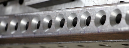

- 23.12.2013: Three test rods mounted and checked for produced pitch.
 In the next picture the set screws for tuning adjustment are shown:
 Calculation
utility, based an acoustics theory books formulas programmed in Power Basic
Console Compiler. (Source code: rodo.bas). Kuhnke solenoids selected: type
HM157.F.24 VDC.100%ED. Extra bronze rods ordered from Demar-Lux. Hand reamer
8.0 mm purchased as well as a new set of M6 threading tools (hand taps).
- 24.12.2013: Calculation and design works. M6 x 16 set screws bought from
MEA. Work slowed down due to an emergency admission in the hospital: muscle
fraction or hernia attack.
- 25.12.2013: Precision measurement of resonance under forced excitation.
- 26.12.2013: Working out experimental results and comparison with theoretical
values. A program written to calculate all rod lengths such that we can start
sawing all rods to size.
- 27.12.2013: Total cost of the bronze tone rods will amount to 523 Euro.
The cost of this alloy amounts to 27.52 Euro a kg. Further drilling of the
5mm holes for clamping the rods. Threading to M6 for set screws. Surface grinding
to remove rusts and light polishing. All holes for the rods drilled to 7.9
mm and further honed to exactly 8.00 mm. First set of six tone rods cut to
size and tested for tuning.
- 28.12.2013: The total length of all rods together will be 21.597 m, so with
a mass of 0.4 kg/m the weight of all staves together will be 8,638 kg. Experiments
with different soundboard shapes and materials. Polystyrene works well if
clamped between the rod-holder and a strong piece of staff material. Wood
also sounds well, but we may have trouble finding a large enough soundboard.
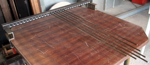 Two end holes drilled
in the cast iron stave and provided with M12 threads for mounting the soundboard.
Start construction of the solenoid holding profile. This will be made from
a length of aluminum 50x30x3 L-profile. We did choose aluminum because its
better for dissipating the heath from the solenoids. The solenoids are mounted
with two M3x6 bolts each.
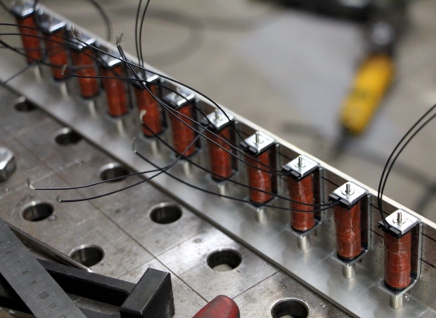
 For the beaters
we plan to use M4 threaded Bakelite spheres. Inserts to fit the M2 threads
on the solenoid anchors to be constructed from M4x8 setscrews.
- 29.12.2013: Damn, Sunday... shops are closed. Continuing work on the solenoid
assembly. First attempt to prepare a beater: the 15 mm Bakelite balls have
an internal M4 thread, about 12 mm deep. So, we drill a 1.4 mm hole in a M4x10
setscrew on the lathe and after this we cut an M2 thread -by hand, in three
passes- in the hole. We will have to do this 31 times... First attempts very
unsuccessful.
- 30.12.2013: Considering the possibility to add a very strong electromagnet
just under the cast iron bar to allow the rods so sing. The input signal could
either come from the rods (in controlled feedback mode) or from an ARM processor
with properly adapted wave synthesis. Design of a damper bar to be placed
over the rods, driven by another set of solenoids. To 50 mm wide pieces cut
of from an HEA 100 profile to test usability as standoff's for the cast iron
bar. M4 x 8 setscrews bought from MEA, together with a new set of handtaps
M2. Threading these setscrews with M2 threads seems to become an endless,
if not impossible undertaking by hand. In a couple of hours, all our M2 taps
broke and we didn't even get a single bolt finished... At a cost of 30 Euro's
for a set of taps, this is becoming prohibitive. Looking for alternatives:
having this part of the job done in an automated factory, or drill 2 mm holes
and glue the anchors to the set screws with cyanoacrylate glue.
- 31.12.2013: Flatface grinder (Bernardo, Austria), ordered months ago, came
flowing in. Design of a possible driver circuit for the electromagnetic activation
of the cast iron bar. We will have to take the octaving problem into account!
We could use an Axo ARM board to do the signal processing, if Johannes Taelmans
firmware is capable enough for handling this. Version 1 of a welding plan
for the chassis and trolley worked out.
- 01.01.2014: Wheel base worked out. We will use spoke wheels again, as on
<Whisper>.
- 02.01.2014: Thread adapters M4-male to M2-female seem to exist! We ordered
them from Newport, type nr. TR-M2M4. They are expensive though: 360 Euro for
100 pieces.
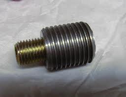 Spoke wheels ordered from Kaiser+Kraft. (415 mm x 60 mm, 120 Euro each).
- 05.01.2014: What about using an old bulk eraser as an electromagnetic driver
for the cast iron bar? Digged one up dating from the seventies: Radio Shack,
100 W / 220 V bulk eraser, maximum on-time: 1 minute. Tried on Rodo and it
seems like it's going to work if we feed if with a high voltage signal. The
DC resistance of the coil was measured as 21.27 Ohm, the inductance as 312
mH at 1 kHz, raising to 325 mH at 100 Hz and 344 mH at 10 kHz.
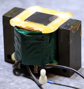 The picture shows the electromagnet as found in the bulk eraser.
- 06.01.2014: Design of the power amplifier module for driving the electromagnetic
exciter. The M4x6 setscrew, M2 taps and the vibration dampers ordered from
Fabory came in.
- 07.01.2014: Steel cutting and welding works on the under-chassis. Horizontal
structure uses stainless steel 50x50x2 profiles. Wheel holders: 50x30x3. Welding
plan further worked out.
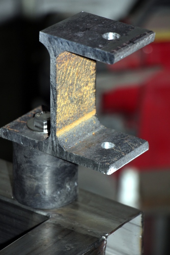
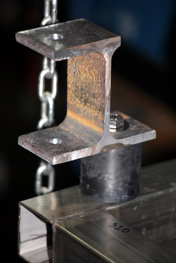 The pictures show
the assembly of the holders for the cast iron bar. The soundboard is not mounted
here, but will be fitted between the HEA100 profile and the rubber damper.
- 08.01.2014: Experiments with soundboard materials. Start construction of
the damper assembly, using Lucas Ledex tubular solenoids (push type), from
a length of aluminum 50 x 30 x 3 L profile (same as used for the beater assembly).
The holes for the solenoids are 14 mm and the threads on the solenoids are
M14 x 1.5. The distance between the holes is -as for the beaters- 30 mm. We
will have to provide a spring inside the solenoids with a strength such that
as rest the dampers to not make contact with the tone rods. We may have to
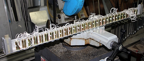
order these custom made from Veren Algoet. Here is the damper solenoid assembly
without the plungers and the damper heads:
- 09.01.2014: Design of adjustable mounts for both the beater- and the damper
assembly. Adjustment should be possible both horizontally and vertically.
Horizontal range: 80 mm, vertical range 120 mm. Cutting of the 31 damper felts
(diameter 25 mm, 10 mm thick) using the arbor press and a dinking die.
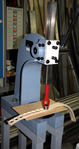 These felt pads will be glued on 25 mm conical valves mounted upside down.
The centered 2 mm hole has to be slightly enlarged as the plungers have a
stem diameter of 2.35 mm.
- 10.01.2014: We cannot assemble and test the dampers as long as we did not
fit the return springs. The felt dampers have to be glued on the plungers
and then cannot be easily removed again. The ordered M4-M2 thread adapters
came in from Micro-Controle Spectra-Physics s.a.
- 11.01.2014: Start coding for the beater PIC-controller boards. The source
code for these, under development, is at http://www.logosfoundation.org/instrum_gwr/rodo/picworks/Rodo_Beaters1.bas.
It must be compiled using the Proton Compiler in combination with MPLAB.
- 12.01.2014: First version of the firmware for the damper controller boards.
This can be found back at http://www.logosfoundation.org/instrum_gwr/rodo/picworks/Rodo_Dampers1.bas.
We still have to assemble the boards though. Support for <Rodo> added
in our GMT software, so we can perform the required testing. Construction
of the return springs and the brass discs to retain them on the plungers holding
the dampers. To make these brass discs, we used the arbor press with a 10
mm dinking die on 0.5 mm thick brass foil (sheet metal).
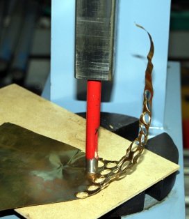 The brass discs were glued on the flat plunger end using Loctite 401 cyanoacrylate
glue. For the return springs we used the same type as we had custom made for
the player piano robots. Note that very much on purpose we dropped the springs
over the plungers whilst the glue had not fully set, thus they are also glued
to the plungers at their end.
  Since
the springs unavoidably tend to make the plungers, and thus with them the
dampers, bounce on release, we may have to add a felt covered debouncing bar
over the entire assembly. This is as yet to be experimentally found out. Gluing
of the 25 mm felt discs to the inverted conical valves, using Loctite 5920
copper silicon. We prepared the 2 mm holes in the conical valves by hammering
a spare plunger with the 2.35 mm shaft in them to a depth of 6 mm. This enlarges
the holes in the wood slightly and makes a tight fit later on. As the silicone
tends to creep slightly through the hole, we may have to use the arbor press
again to force the plungers into the felt holders.
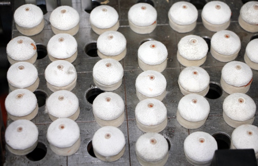
- 13.01.2014: Suitable transformer digged up for the damper power supply:
12V /25A. Firmware version 1.0 for beater-pic and damper-pic uploaded in two
chips and tested on our test-board with the GMT code. Functionally everything
seems to run fine. Controllers 14,15,16,64 tested under GMT. Note-off with
release runs fine as well. The scaling of course will depend on the behaviour
on the instrument itself. Firmware source code edited in order to program
the second beater and damper PIC's. In principle we have all four chips ready
for testing now. Soldering works on the midi-pulse boards started.
- 14.01.2014: Design work for the power supplies. As we want to avoid using
SMPS types (because of the trouble we had with them in the past with fast
switching solenoid loads and both EMC and emitted ultrasound) , we have to
come up with a very stable design capable of delivering at least 20 A. A bunch
of LT1084CP12 type 12 V/5 A regulators, operating in parallel may be a viable
solution. If we add power diodes and maybe a small resistor in series with
the output, we could even easily get at ca. 10 V, just a bit over the 9.4
V 100% duty cycle specification for the damper solenoids.
- 15.01.2014: Traced a factory that could cut out the required sound board
from polystyrene (Isomo, brand name for styrofoam).
- 16.01.2014: Technical drawing prepared. The voltage regulators 12 V/ 5 A
(LT1084CP12) came in from Farnell together with a fresh load of 18F4620 microprocessors.
Further design and calculations on the power supplies.
- 17.01.2014: Drawing a design for a PC board. If we want to place all (heavy
and large) components on the board, we need at least a 3 mm thick PC board.
Taking into account the very high currents involved, we decided to hand-make
a double sided PC board using adhesive copper foil. It looks a bit primitive...
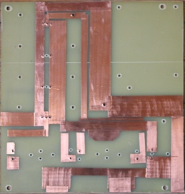
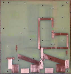
- 18.01.2014: Assembly of the experimental board for the 25`A / 12 V power
supply. Carefull tinning of the adhesive copper foil is essential as the adhesive
itself in non-conductive. This is the copper side after tinning:
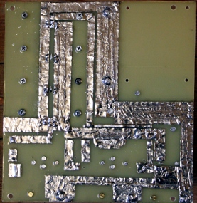 We
got the entire power supply ready now. Testing also performed. Voltage over
the big capacitor measures 15 V. 12 V light supply measures 12.0 V, whereas
the outputs for the damper solenoids measure 11.8 V without load. Here is
the finished module:
  Sizes are 270 x 260 x 170 mm, or about twice as large as a comparable SMPS
power supply. The output terminals are formed from brass M4 bolts and nuts,
soldered on the copper side of the board.
- 19.01.2014: Soldering works on the solenoid driver boards. 112 IRL640 Mosfets
in total on these boards alone...
 Some
3500 solder joints to be done. Start work on the assembly of the 48/60V power
supply. Here also we use an epoxy carrier board.
- 20.01.2014: Further work on the 48/60V power supply. This carrier board
can also hold the transformer for the 5V logic power supply. The regulators
are on board of the pulse boards, so these just need a 6 V AC source. Sizes
are: 270 x 120 x 140 mm.
 Start
construction of the carrier board for the ILP HY2005 power amp module and
its toroidal transformer. The link has to be soldered on the module, as required
for 8 Ohm operation. For good impedance matching, we will have to use a matching
transformer on the output. Maybe be could recycle an old vacuum-tube amplifier
output transformer. We should still have a few 100 W vacuum tube amplifiers
around... Maximum output voltage from the ILP amp is 31 Vrms, so a 1:10 voltage
ratio transformer should do the job.
- 21.01.2014: Finishing the power amplifier module. This sizes 270 x 120 x
90 mm.
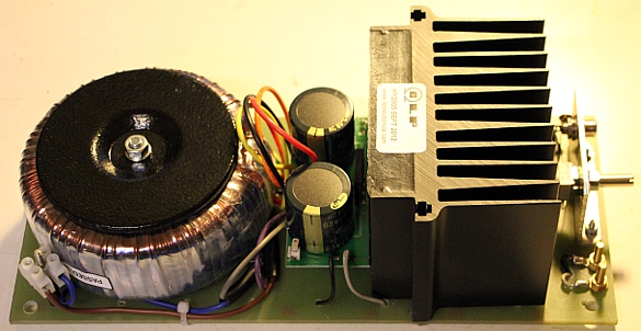 It's not large
enough to also fit the required impedance matching transformer. For this we
could also try a toroidal 2 x 35V to 230V rated for 160 W. It might be a good
idea to fit the bulk eraser coil with a temperature sensor that could be read
by the ARM board processor, such that a burn-out protection would be implemented.
- 22.01.2014: Instead of providing a temperature sensor on the bulk eraser,
we decided to simply equip it with a temperature switch on the windings, such
that the circuit breaks if ever the coil gets too hot. Looking at the design
now, it seems a bit stupid to use the impedance transformer. Instead we would
have done much better by rewinding the coil on the coil former of the bulk
eraser assembly to give it an inherent 8 Ohm impedance... But, obviously,
coil winding by hand is always a pretty tedious job. Block terminal contacts
ordered from Farnell. Styrofoam boards (4 pieces, as we expect accidents to
happen...) ordered to use as soundboard. Redesign of the stainless steel structure.
Suffering from a hernia, we have to postpone the cutting and welding works
a bit it seems.
- 23.01.2014: Very gentle -because of the hernia- TIG welding works on the
wheel base for the back wheels. Stainless steel profiles used: 50 x 30 x 2.
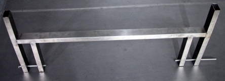 Start working on
the adjustable holders for the beater and damper mechanisms. The are to be
made from 10 mm thick staff material.
- 24.01.2014: Holders with slides for M8 and M10 bolts finished. Cutting,
welding, grinding. One for the left side, one for the right side. The vertical
slide made from 25 x 10 staff material, the horizontal one from 20 x 10 material
such that the total height is exactly 50 mm.
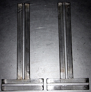
- 25.01.2014: Holes drilled in chassis and slides mounted and tested.
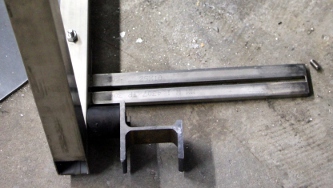 Construction
of the slide for mounting the electromagnetic driver. Three bars of 20 x 10
x 300 stainless steel, welded together with two 10 mm gaps. The core of the
driver is only 24 mm wide, so we need a pair of spacers to adjust it such
as to strike in the middle of the 40 mm wide cast iron bar. The spacer ought
to be 8 mm and can be welded on the slide.
 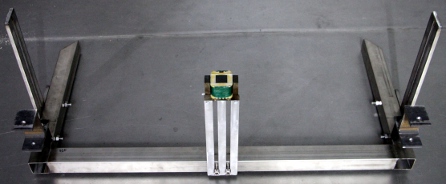 Mounting
holes for the solenoid are 5 mm. Bolts for the slide must be M10 x 70 or M10
x 80. Possible front wheel mechanism found in the hardware store. Hoping to
dig up a suitable wheel now from our collection...
- 26.01.2014: Finalizing the e-drive mechanism. Start construction of the
bend sides of the main chassis. These sides are made from two pieces of 50
x 5 x 820 stainless steel. Bending by hand in a large vise clamp. Welded on
the back chassis on the welding table.
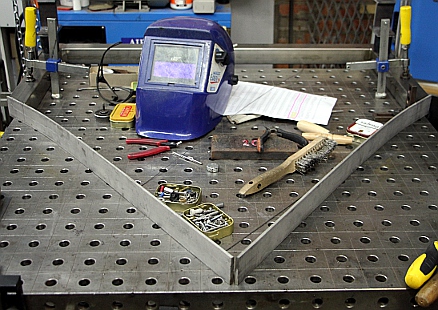 .
Further works on the front wheel design. Building height of the wheel will
be 240 mm. The mounting plate measures 110 x 140 mm.
- 27.01.2014: Still waiting for the spoke wheels, the brass rods and the styrofoam
soundboard... Panel voltmeter (moving coil) with range 300V ac added for monitoring
the e-drive output. (Type YH670, class 2.5) Mounted on an small aluminum subpanel
on the board housing the impedance transformer. Holes drilled for he circuitry
holding panels to be cut out from 2 mm thick stainless steel plates. So, we
decided not to weld these on, but rather to make them removable for ease of
maintenance and final assembly. Instrument under construction explained to
a small group of students.
- 28.01.2014: Cutting and bending of the mounting plate for the power supplies,
mains switch, I/O connectors etc. Cut from 2 mm thick stainless steel, left
over from the construction of the Logos building. The wheels came in, unfortunately
they came with spindle holes 20 mm in size instead of the 12 mm we had already
drilled in the chassis... Holes drilled for mounting of the supply components,
for the MIDI I/O connectors, the mains entry, mains power switch and a switch
for mode of operation selection (autonomous robot / midi controlled automaton).
- 29.01.2014: Mounting of the connectors on the bottom plate. Test mount of
the bottom plate assembly. We need 6 mm hole mounting studs in PTFE or Epramid.
The styrofoam sound boards still did not come in!
- 30.01.2014: Bending of the back wheel structure to bring it perfectly in
shape after welding deformations. Construction of the 20 mm shafts for the
back wheels.
- 03.02.2014: The stock of bronze rods came in from Demar-Lux. Still no styrofoam
boards though...
- 05.02.2014: M12 threads made in the wheel shafts. The wheels can be mounted
now. Cutting of the tone rods from bronze staff material... trouble though:
the composition is different than that of our test staves. Either we have
to re-order the staves, or recalculate the staves for the new alloy.
- 06-17.02.2014: Research on sensor systems and information retrieval to be
used for the robotic components in <Rodo> but also for the gesture recognition
coding under GMT.
- 18.02.2014: Test mounting of the power supply carrying plate on the lower
wheel chassis. The M10 mounting bolts will have to welded op the base plate.
Test mount of the power supply assemblies on M6 MF threaded vibration dampers.
Cutting of the two holders for the 12V LED spotlights underneath (50mm diameter
stainless steel tube, length 50mm).
- 21.02.2014: Distance holders turned on the lathe from epramid staff material.
Vibration dampers would after all have been overkill here. M10 bolts welded
on the power supply assembly.
- 22.02.2014: Spotlight holders constructed for mounting on the power supply
plate. These are adjustable.
- 23.02.2014: Assembly of the back wheels, the wheelbase and mounting on the
horizontal skeleton. Welding on the horizontal structure.
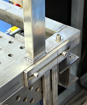
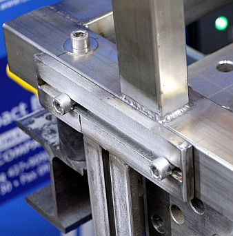
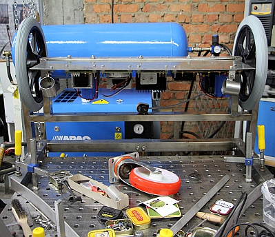 Start
construction of the front wheel structure. Still very handicapped by a hernia...
- 24.02.2014: Construction of the front wheel. Welding works. Wheel mounting
plate: 160 x 100 x 10, with four 10mm holes. Vertically inclined pole: 100
x 50 x 2 profile. Mounting plate welded on chassis, cut out from 3mm stainless
steel plate.
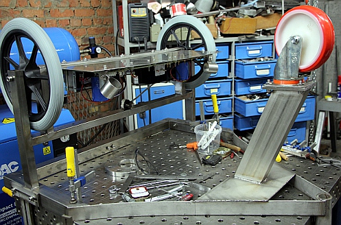
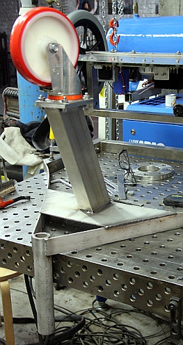
- 25.02.2014: Drawing and plasma cutting of the carrier plate for the microcontrollers
and the robotic components. Construction of two light holders for the front
next to the frontal wheel. First tests with styrofoam soundboard.
- 26.02.2014: Drilling and honing of all mounting holes on the microcontroller
plate. The plate can be taken out by loosening the five M10x50 and two M10
x 25 bolts. Construction of the mounting plate (vertical) for the four PIC
processor boards. This assembly mounts on the backside of the horizontal plate
with two M12 bolts.
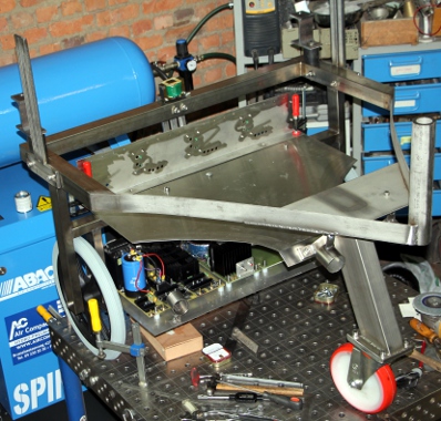
 With the help of Sebastian, Mattias and Kristof, we managed to flip the entire
construction and bring it back in position on the welding table...
 Two blue LED spotlites
mounted in their holders on the front and two yellow LED spotlites in the
holders on the power supply plate.
- 27.02.2014: Instruction to the instrument building students at the conservatory
about the ongoing <Rodo> project. Tools and techniques explained. Wiring
of the on/off switch and the midi-input connections. We will leave the drilling
of the mounting holes for the robotic components for later on, as we do not
now the sizing of these components yet.
- 28.02.2014: Start wiring of the power supply lines.
- 01.03.2014: Continued wiring of the PIC processor boards. Mounting and wiring
done (except the dampers and the solenoids) such that we can test the board
and the initial coding in the firmware. Yellow LED spotlites mapped on notes
114 and 115 and controlled by the Dampers-1 microcontroller board. At first
boot, with all voltages applied, everything seems to run fine.
- 03.03.2014: Tracing a suitable transformer for the required +24V voltages
for the LED strips and the sonar sensor. An old transformer block from a HP
inkjet printer may do the job. Rodo project demonstration for Brent Wetters.
- 04.03.2014: Design of the dual +24V power supply.
- 05.03.2014: Dual + 24V power supply soldered and tested. HP transformerblock
mounted on the power supply chassis plate. This was done using two strap ties
and some parabond under the transformer housing. Wiring of the e-drive module.
We mount the components for the 24V supply on this same subchassis module.
The 24V power supply has two separate outputs and uses a Weidmueller connector.
- 06.03.2014: All ground connections made. Alu-bronze bars delivered. Bronze
cutting with the students.
- 07.03.2014: Front lights wired. Test mount of the mechanism. Cutting and
first tuning of the bronze staves.
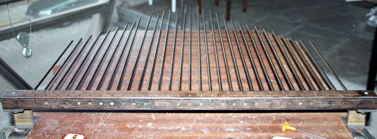 Two out of the eight rods in the new delivery appeared to be cast from a different
alloy again, so we had to re-cut them. A lesson learned: never trust batches
of delivered alloys to be identical...
- 08.03.2014: Support for the front of the styrofoam soundboard designed and
constructed.
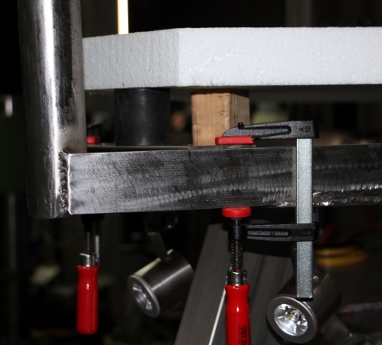 Bakelite
beaters loosely screwed on the beater anchors. The wite stuff underneath the
beaters on the picture is the styrofoam soundboard.
 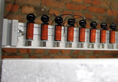 Start wiring of the solenoids. Wiring just the beater solenoids took us a
full day and still we have to do the Weidmueller connectors. Wire colors follow
resistor color coding, staring with note 48 being black. The common positive
voltage is the thick red wire. A white LED strip (24V) is mounted on the userside
of the beater assembly. These LED strips require 240mA current (4.5W), so
we should be carefull not to exceed the limits of the 24V power supply if
we are adding more of these lights...
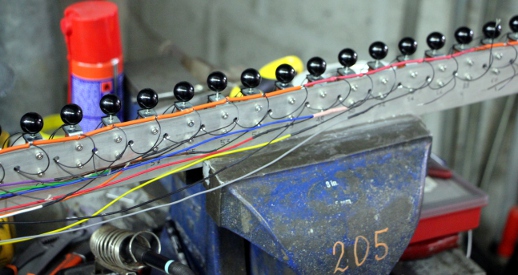
- 09.03.2014: Wiring of the beater Weidmueller connectors: two boards. If
we mounted the tone rods, rodo could play already... Electrical tests o.k.
Design of a strong red LED light assembly for the underside. This uses 1W
LED's in SMD technology. Styrofoam soundboard cut to shape with a razor blade.
Frontal holder for the soundboard welded on.
- 10.03.2014: First test mount of the rod assembly on the styrofoam soundboard:
deceptive results, as the styrofoam is clearly not strong enough to hold the
weight and the pressure of the rod assembly. We could try to increase the
contact surface, for instance by mounting the rod assembly via a piece of
wood on the soundboard. On the underside, a larger surface is required as
well. So, we did cut out four pieces of wood and indeed, now it works fine
and with good resonance. In the definitive version we should remake these
pieces of wood from real good quality hardwood 10 mm thick and 50 mm wide.
(Meranti) As an alternative we could also try out titanium here.
- 11.03.2014: In need of long bolts M12, M10 and M8... up to MEA. Four support
plates sawn out from long aged tropical hardwood, thickness 8 mm. Now the
sound is o.k. It may be better not to support the front of the styrofoam,
as supporting it gives some damping of the lower frequencies.
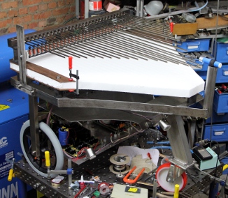 First tests of the electromagnetic drive mechanism, using a tone generator
leading to a large smoke stack... Something is fundamentally wrong here...
Almost certainly we exceeded the 500mV max. input level.... Analysis of the
board revealed that the elco's exploded. 4.7mF/63V types, presumably with
an MTBF below 3000 hours. We will try to replace them with decent quality
100V types and hope the amp has survived it.
- 12.03.2014: Apparently, not the elco's exploded, but the HY2005 module itself.
Bad luck... and high costs. As the HY2005 is no longer in production at ILP,
we will have to replace it with the ILP HY2004 type and adding a power supply
externally. Mattias Parent helps us out adjusting the Bakelite beaters for
a trajectory of 5.5mm to the tines. <Rodo> produces its very first tones
and scales under computer control! Apparently we forgot to implement the blue
LED spotlights on the front in de firmware for damper PIC1. Firmware revised,
not yet in the chip. GMT test-code adapted to make measurement of good velocity
scalings for the beaters possible. Our tests in this matter lead us to new
analysis of solenoid behaviour under fast repetition conditions. If the time
between two pulses becomes smaller than the fallback time of the anchor and
its load, the anchor will assume a 'floating' position without coming down.
As the pulse time is increased, the distance to the struck object becomes
smaller, repetition time can be increased but sound volume will go down. If
you go beyond the duty cycle limits, obviously the solenoid will burn out.
This confirms our observation that for very fast repetition rates, very low
velocity values have to be used.
- 13.03.2014: Working session with the instrument building students at the
Conservatory. Acoustic theory of styrofoam explained and demonstrated. Introduction
in welding technology. Firmware version 1.2 uploaded for beater PIC2, with
'dead-time' after strike provisions and new velocity scalings.
- 14.03.2014: Continued work on the damper assembly. All solenoids wired:
a full working day.... Weidmueller connectors to be done.
- 15.03.2014: Mounting of the damper felts on the solenoid anchors.
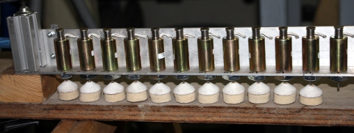 Wiring
of the Weidmueller connectors. The boards are up and running now. Further
work on the firmware is required.
- 16.03.2014: Bounce-back bar over the damper assembly mounted.
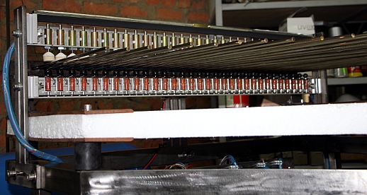 This
bar carries also the engraved brass nameplate 'me fecit logos'. Firmware development
for the damper controllers. Midi implementation updated. The time the dampers
stay in contact with the tines can be controlled within the range 6 ms to
767 ms. Either the note-off release value or controller #14 can be used to
control this. Lights 116,117,118,119 implemented on the second damperboard,
although we have as yet no lights connected there. Rodo plays well now and
can be given in the hands of users/composers for evaluation. All controllers
implemented sofar tested with the coding in GMT.
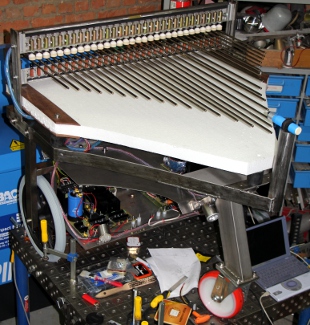 The left blue light appeared to be broken. Probably because of the strong
electromagnetic fields welding works caued too close to the LED... LED spotlite
replaced.
- 17.03.2014: Meeting with Kristof Lauwers on the way we are going to implement
the electromagnetic drive mechanism. The power amp (HY2004) has been replaced
and works fine now. We have to keep an eye on input and output conditions
though. Never ever exceed 500mV on the input! The frequency range should be
limited to 20Hz - 260Hz range. In the lowest range, resonances with the dampers
do occur.
- 18.03-21.03.2014: Kristof Lauwers at work on the development of the code
and patches for the ARM board, Axo project.
- 21.03.2014: Two red LED lights mounted on the underside. These need a 18
Ohm series resistor to work on 12 V DC. Each of these LED clusters draws ca.
200mA. Here is the datasheet.
- 22.03.2014: Finalisation of the wiring for the red lights. These are mapped
on midi notes 120 and 121, controlled by the PIC for the second set of beaters.
Power comes from the +12V lights power supply.
- 23.03.2014: Continued tests and evaluations on the e-drive mechanism. GMT
test-code further improved.
- 25.03.2014: Work session with the Axo firmware as developed by Kristof Lauwers.
- 26.03.2014: Axo board problems: input attenuator unavailable, variable midi
channel not implemented, strange behavior with output volumes. To be discussed
with Johannes Taelman. It seems the audio inputs on the board are very high
sensitivity and do not have an attenuator...
- 27.03.2014: Wiring of the Honeywell 944-T4V-2D-1C1-130E distance sensor
connector. The connector is Hirschmann type ELKA 5012 PG7, 5 pole , order
nr.933 170-100. The responsiveness of the distance sensor appears to be very
slow. Here is a link to the sensors manual.
- 28.03.2014: Distance data is refreshed only once every 1.2 seconds using
this Honeywell sensor.
- 31.03 - 03.04. 2014: Continued work on the ARM firmware by Kristof Lauwers.
- 03.04.2014: <Rodo> lifted from the welding table as we needed it to
be free for the construction of the <Snar2> robot. Now set up in the
center of the tetrahedron...
- 06.04.2014: The first interactive piece for <Rodo> is in the making:
Namuda Study #44.
First rehearsal with Dominica Eyckmans.
- 07.04.2014: Further debugging of the ARM coding.
- 08.04.2014: There must be a small bug in the PIC firmware for the beaters.
It doesn't seem to work under running status conditions. The dampers behave
correctly here...
- 09.04.2014: Bug found in the beater firmware. Repaired and both chips reprogrammed
with version 1.3
- 10.04.2014: Adding rotating red warning light, 24V. Mapped on midi note
126 and controlled by beater PIC 1.
- 11.04.2014: Television shooting session with Rodo for VRT 1.
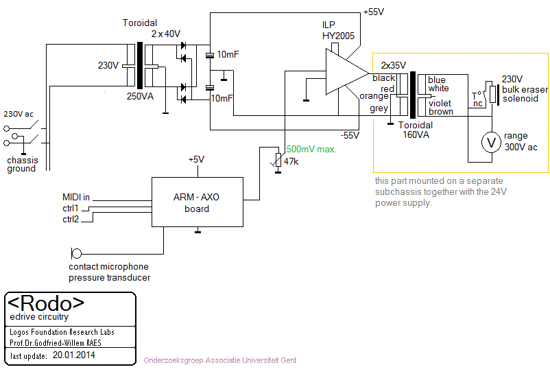
- 12.04.2014: Attempts to power the ARM board from the general +5V V DC supply
such that is does no longer require the USB connection. Code tested for playing
Rodo with the dampers alone. This is the circuit:
- 13.04.2014: Rehearsal session with Dominica Eyckmans:
Rods for Rodo, namuda study #44.
- 14.04.2014: Stand-alone operation of the ARM/Axo board succesfull. The connectors
to the board are a bit shaky however. Start design of a PC board for the analog
input channels and sensing components.
- 16.04.2014: <Rodo> plays for the first time in public.
- 16.07.2014: Impedance transformer board soldered and mounted for the piezo-disks.
1:10 audio transformers used. This way there is no more risk for overloading
the ARM-AXO board input.
- 11.02.2016: Failure of the e-bow mechanism. Apparently the power amp is
dead. Maybe we should redesign this, for instance by using a Visaton exciter
instead of the electromagnet. This would greatly simplify the circuitry. However
we first have to find out what it sounds like. Drivers already ordered from
Reichelt.
- 14.02.2016: Repairing the original circuit, with an added diode compressor:
 HY2004 amplifier module replaced. Measurements: with 160V ac on the output
transformer and over the driven electromagnet, the HY2004 gets pretty hot.
The amp output is delivering 23.5V to the transformer then, so it ought to
be well within specs... (66V pp output, that is).
- 16.02.2016: HY2004 burned out again, despite the input protection, in the
music for our 'Oorsprong' production... Alternative approach seems required.
- 18.02.2016: 'Oorsprong' production done by using an external Maranz amplifier
replacing the HY2004. This is a temporary fix though.
- 14.03.2017: Redesigning the e-drive mechanism, using a dsPIC instead of
the ARM driving an IGBT in high frequency PWM mode. This is a pure digital
approach.
- 15.03.2017: Here is the new circuit:
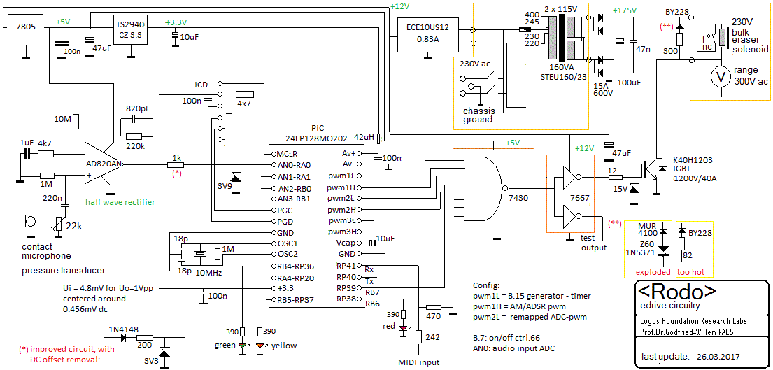 Start of the design of an appropriate PCB. A very large heatsink is an absolute
requirement here. ARM board firmware for the sensor components (Axo platform)
by Kristof Lauwers and Johannes Taelman will no longer be needed, as we will
remove the Axo board.
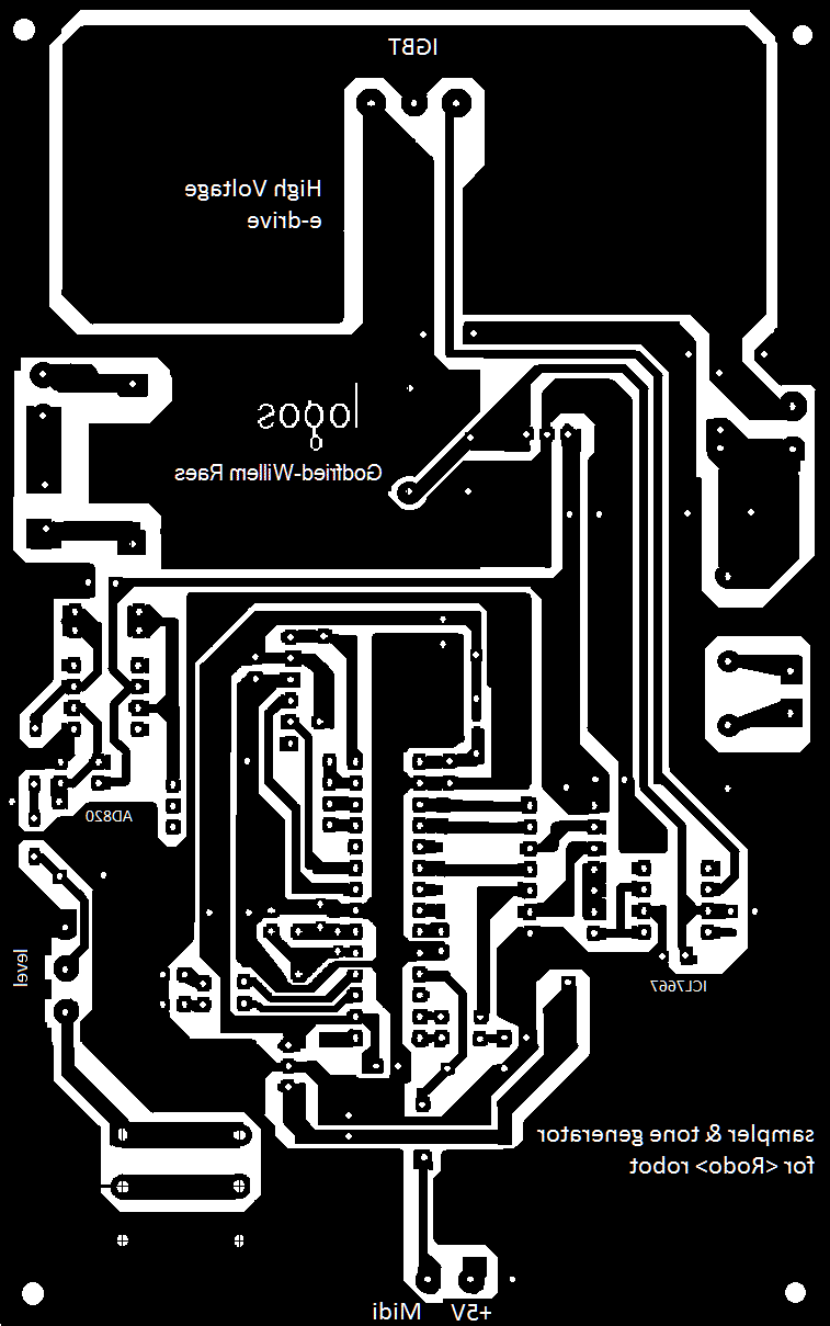
- 16.03.2017: As we explained in full in our article on 'Expression Control
in Musical Automatons', the e-drive mechanism -not having a permanent magnet-
operates as a frequency doubler. Hence the unipolar rectification of the input
signal. Here is the design for the PCB (scaled at 200%):
- 17.03.2017: New PCB soldered. Start coding the new firmware and trying to
stick as much as possible to the original implementation.
- 18.03.2017: First tests revealed a bug in the hardware logic: the 7400 quad
nand gates is a mistake. We can solve the problem by replacing the chip with
a 74HCT30 8-input NAND-gate and pulling unused inputs up. PCB design modified
for future productions using all available pwm outputs from the microprocessor
chip. Midi implementation changed. Further work on the PIC 24EP firmware.
The ADC subsystem works now, but there are problems with the preamp. We configured
the ADC to work in 12 bit mode, so with an input range up to 3.3V this means
the resolution is 0.8mV. The preamp has a gain of 220k / 4k7 = 46, thus the
input signal should be limited to <= 0.072V and the resolution becomes
17uV, so near to the noise level to be expected. Is there a mistake in this
reasoning? Should we sync the sampling rate with the PWM base frequency? Should
we OR the values of PDC1 and PDC2?
- 19.03.2017: Indeed, there was a silly mistake in the opamp input circuit:
Uo = (U+ - U-) Av ,for U+=0 could only give negative voltages on the output
but as we use a unipolar supply this is impossible and thus the output will
be zero at all times... We should have used the non-inverting configuration.
As to the firmware: operating conditions are PTPER = 4096 (12-bit resolution
on the PWM) and PWM base frequency = n. Sampling_Rate . 4096, where n = 1,2,3,...
Still many troubles in getting the ADC to work properly.
- 20.03.2017: Mapping the ADC output on PDC2 might be a conceptual mistake,
as it would require the PWM base frequency to be set to >=20MHz (4096 ^2)
, clearly way above what's possible on the PIC. So, we changed the firmware
such that the ADC values steer timer4 pulsewidths. The timing resolution required
now becomes 59.5ns, still pretty extreme for the PIC as it entails a PWM frequency
of 16.7MHz.
- 21.03.2017: Finally got the ADC system to work properly in 12 bits and with
4096S/s. Now we can mount he IGBT and do the tests under load conditions...
We raised the sampling rate to 16384 S/s, as the 4kHz carrier was too strongly
found in the output in feedback mode. This also works now. Trying again to
steer PWM2 with the ADC. Now we got this working quite well. ILP-amplifier
and power supply removed from the Rodo assembly.
- 22.03.2017: Further work on the modifications of the hardware. Separation
transformer mounted. This transformer is technically not required, but was
added only for safety reasons. We keep the AC voltmeter. However it's still
too cold in the lodge for this kind of work and we have no money anymore to
heat it a bit... PCB design improved, for future projects along similar lines.
Here is a picture of the final board:

- 23.03.2017: Further wiring of the modules on the Rodo chassis.
- 24.03.2017: Start designing the hardware for the gesture sensing system
to be build into this robot.
- 25.03.2017: Design of a PCB for the radar gesture recognition hardware.
Finalising rewiring of all Rodo electronic modules. First testing of the e-drive
circuit: everything fine in the first 10 minutes, then de 1N5371 zener diode
over the driver coil went in smokes to heaven. We have to redesign this part
of the circuit. Should we use a VDR as spike protector or use an RC protection?
The IGBT itself gets barely warm, so that seems to be o.k. The moving coil
AC-voltmeter gives erroneous readings. Likely it does not work well under
high frequency circumstances. The air-gap between the cast iron bar and the
coil has to be enlarged.
- 26.03.2017: E-drive board repaired: de MUR diode exploded and also killed
the 60V zener diode. As a result, ithe IGBT got short circuited and also went
to heaven. As the IGBT c-e junctions were found welded together, the separation
transformer got an overload and its primary got shorted. Result the house
fuse got activated and we found ourselves in the dark. A quite expensive chain
reaction. We replaced the EREA transformer and modified the circuit to work
on 170V. We modified the damper circuit and inserted a BY228 diode in series
with a wirewound 82 Ohm power resistor. Of course we also replaced the IGBT.
It now works again, - the AC voltmeter now works again- but even with the
volume controller halfway, the 47uF electrolytic capacitor gets very hot.
We do not trust it in any case. Looking for a very low ESR type. Studying
the textbooks on MOV's or VDR revealed that they would not be a solution to
our problem here. Maybe we should have a fuse in the primary of the safety
transformer (0,8A, slow). This looks like a better circuit for feeding the
e-drive solenoid:
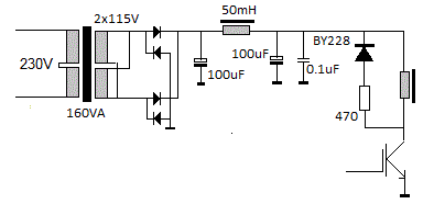 Yet to be tested.
- 27.03.2017: The circuit with a BY227 in series with a 82 Ohm resistor not
only drives the 47uF cap very hot, but at high volumes and duty cycles the
resistor gets yellow hot... The IGBT barely gets warm, so we can have it dissipate
more of the freewheel solenoid voltage. 100uF low ESR caps ordered from Farnell,
as well as a 50mH toroidal choke to build the circuit as designed yesterday.
It seems nearly impossible to calculate the ideal component values for the
freewheel protection circuit. The main reason being that the inductance of
the coil varies widely over electro-mechanical load and frequency conditions.
So the experimental temperature measurement method seems to be the only way
to go here.
- 28.03.2017: PCB repair session. BY228 replaced, 82 Ohms resistor and 47uF
cap removed. Wirewound 300 Ohm resistor mounted and 100uF/450V low ESR electrolytic
mounted. First 15' it worked well, than we noticed overheating of the electromagnet.
The thermal fuse went off. As we measured 170V DC over the coil connections,
we suspect the IGBT to have gone to heaven. The coil, fortunately had a thermal
fuse and disconnected the coil automatically but not a bit too early... We
must reexamine the firmware, as apparently something makes the controller
crash, causing all outputs to go high.
- 29.03.2017: Attempting to reproduce the crash condition on the PIC. A 12
Ohm resistor added in the gate drive circuit for the IGBT as well as a 15V
zener diode. Rodo tested for a couple of hours. So far, no failures detected.
Work continued on the radar interfaces. First prototype of the PCB etched,
drilled and soldered.
- 30.03.2017: Minor bugs removed in the e-drive firmware. (see documentation
in header comments of the source code). First tests of the radar board. There
must be some bugs in the op-amp hardware.
- 31.03.2017: Radar hardware tested: strange observation: the10.5GHz radar
modules have no DC offset and almost no output when uncovered. With a 5 mm
thick plexiglass cover, the DC offset becomes some +100 mV and the sensor
output signal ca. 10mVpp. This is the base circuit for the RADAR interface:
 Measurements performed with the Tektronix TDS2024C:at a movement velocity
of ca. 1 m/s we measure downgoing pulses on the comparator outputs at about
140 Hz. Pulse lenghts are in the order of 7.2 ms. This is in line with what
we expected to get from the datasheet: 1 m/s should give a Doppler shift of
70 Hz. If we set the maximum movement speed to 5 m/s, the shortest valid pulses
we can expect would be 1.5 ms. So, in the firmware handling the external interrupt,
we can disregard everything shorter as being a glitch. At 10 cm/s we could
measure the longest pulses, in the order of 72 ms. Below that speed, the circuit
looses sensitivity very fast because of the high pass filter in the pre-amp
circuit, in particular the 2.2uF capacitor.
- 01.04.2017: Further work on the firmware for the gesture sensing components.
Full documentation in the source code for the firmware. Speed measurement
is implemented using external interrupt on zero cross and pulse duration measurement
using timer 1. Movement amplitude uses the 12-bit ADC, followed by DC removal,
differentiation, rectification and integration. A square root conversion is
used to increase sensitivity at larger distances and/or small movements.
- 02.04.2017: Midi merger coded. Some hardware bugs removed in the base circuit
for the RADAR interface: DC offset resistor values were wrong! The DC level
on the AN0 input should be 1.65 V, not 2.5V as in the first circuit. As a
consequency the comparator voltage levels has to be changed as well. Circuit
drawing updated. Start design of a suitable mapping of gesture into rodo actions.
By the end of the day we had a first interactive code version ready. To be
tested tomorrow...
- 03.04.2017: The modifications on <Rodo> required for the Midi routing
are laid out in the following schematic:
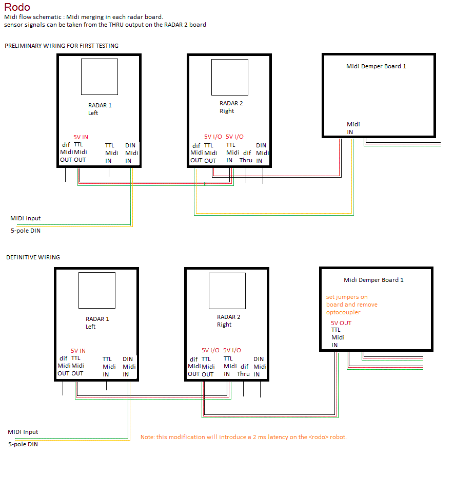 Firsty tests with the radar 1 board connected to <Rodo>. The 'RadaRodo'
piece still needs quite some refinements. The midi-merge functions look like
working o.k. Controllers #70 to #73 added in the Radar firmware.
- 04.04.2017: Further work on the firmware for the first Radar board and the
RadaRodo piece. The startup sequence seems to be quite critical. The radar
board shouldn't send any midi before the other boards are ready to receive
it... The e-bow board has a much longer initialisation time than the radar
board. PCB for radar 2 etched and drilled. Here it is:
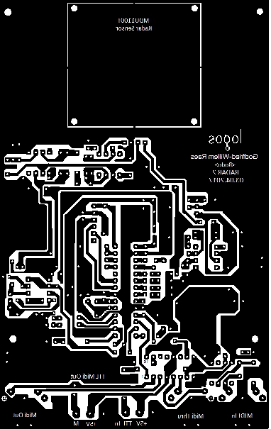
- 05.04.2017: Soldering Radar 2 board. Running out of components and barely
any money left to order new ones... Missing IC sockets, low voltage opamps
(AD820), multiturn 470 ohm trimpots... Here is a picture of the radar board:
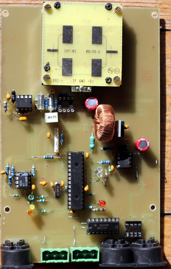 Design of a mounting
plate for the radar boards on the Rodo chassis. Two 100nF SMD capacitors soldered
on the copper side of radar 1 board on the comparator inputs. On board two,
the PCB has provisions for leaded components at this place. Zero cross voltage
difference adjusted to 17mV window. This should give a 40dB sensitivity. The
470 Ohm trimpot can adjust the window size between 0 mV and 342 mV maximum.
Of course the value set should always be somewhat larger than the peak to
peak amplitude of the noise. This sets the sensitivity for movement speed
detection.
- 06.04.2017: AD820 opamp and Bourns 470 Ohm trimpots arrived. Long M12 nuts
TIG-welded on the underplate for mounting of the radar boards. These boards
on their turn are mounted on red plexiglass plates on 3 mm stand-offs with
M3 bolts and nuts. Firmware for the radars modified such that signals below
the amplitude threshold, invalidate speed data. The two radar boards are now
mounted on the left and right side of the robot.
- 07.04.2017: Further work on the radar firmware and the gesture recognition.
- 08-09.04.2017: Big trouble with firmware. Got solved after two days: dont
use floats in ISR's. Dont enable/disable interrupts from within interrupts.
Hardware bug discovered: 1Vpp oscillation on analog 3v3 power input pin for
the PIC. 22uH coil removed and replaced with a 1 Ohm wirewound resistor. Integration
performed in the tasking code using floating point.
- 10.04.2017: Extensive testing of <Rodo> with both radar sensors mounted.
After some 3 hours of operation, radar 2 seems to oscillate as radar 1 did
yesterday. Difficult to reproduce problem, as it doesn't seem to reappear
on the lab table. The firmware itself seems to be stable now. Another traces
we could follow are: frequency shift interference between both radars and
vibration transfer from the ebows to the radars.
- 11.04.2017: Apparently there is an interference between the ebow and the
radars. Either mechanical or electromagnetic.
- 12.04.2017: Based on the experiences gained in the development of these
two radar sensors, we designed a slightly improved version in which we use
a Schmitt trigger with adjustable thresholds for frequency measurement, replacing
the window comparator we had in the first version. A PCB for this new version
was designed as well. As further development of this circuit is no longer
relevant for the <Rodo> design, we created a separate webpage to document
research on this line. All relevant documents are now to be found at : http://www.logosfoundation.org/ii/Radar_2017/
- 13.04.2017: Further work on the embedded composition code in the <Rodo>
firmware. Production of the PCB of the new radar design.
- 14.04.2017: Radar3 board finished and up and working. The comparator works
much better here.
- 15.04.2017: Further work on the embedded interactive composition 'RadaRodo'.
- 16.04.2017: In depth test of reliability.
- 17.04.2017: Handgrips, at the same time polystyrene protectors, mounted
on the frontal sides of <Rodo>. Playing around with the stack size in
the firmware as there are 'unexplainable' issues. Increasing stack size did
not change anything, so the default stack size must have been o.k.
- 18.04.2017: Comparator circuit in the radar hardware changed. Window comparator
dropped in favor of a Schmitt trigger configuration.
- 19.04.2017: First public demonstration of the <Rodo> robot as an interactive
machine.
- 20.04.2017: Speed of movement detection algorithm improved. Now it will
work for speeds between 1 cm/s and 5 m/s.
- 28.04.2017: Rodo demonstration for Bart Carron.
- 29.04.2017: Failure of the e-drive power MOSFET.... This was caused by programming
the e-bow controller with the power on. We should never do this, as during
programming we have no control as to the logic states of the I/O pins of the
processor. Apparently, they all go high... We had to replace the IGBT.
- 30.04.2017: Failing again, but this time nothing wrong with the IGBT: we
just caused a short with a little piece of desoldering litze whilst replacing
the IGBT. Everything works fine again now. Still more work to be done on the
interactive coding.
- 03.05.2017: Further work on the embedded composition code.
- 30.05.2017: Midi source and MP3 recording of Study #23 for <Rodo>
uploaded.
- 09-11.11.2018: <Rodo> played three days continuously as an autonomous
robot at the occasion of the festivities around the 50th anniversary of Logos.
- 17.11.2019: <Rodo> active for Kinderkunstendag in interactive mode.
- 27.08.2021: <Rodo> transported to the SMAK museum for an interactive
exhibition curated by Philippe Druez.
- 02.09.2021: Some odd interference of the radar transducers observed. In
order to avoid too much activity from <Rodo> in this setup with other
members of the robot orchestra, we need to build a timer.
- 06.09.2021: Timer circuit finished and tested:
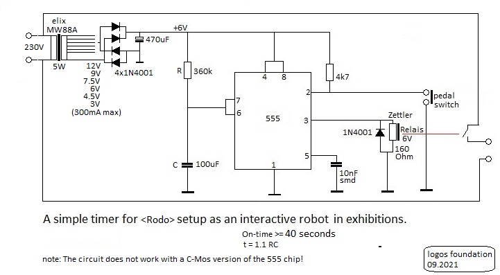 The strange observation is that simply touching anything connected to pin
2 of the 555 timer chip, triggers the timer. Thus, we do not even need the
microswitch...
- 13.08.2022: <Rodo> tested thoroughly: adjustments needed for the rod
playing note 57. Rodo will have a part in my monumental composition 'Linac
Electa' to be premiered august 18th.
- 01.07.2024: Catastrophic failure on turning on <Rodo>: e-bow coil
burned out as well as its driver board including the hefty separation transformer.
Big flames and smoke stack... Looks like the failure on 26.03.2017 happened
again...
- 27.09.2024: Driver coil rewound on the E-core recycled from the original
bulk-eraser. Copper wire diameter 1.5 mm. Measurement after winding: L = 1
mH, Rdc = 2.8 Ohm, so the impedance at 1000 Hz ought now to be 6.2 + 2.8 =
9 Ohms. This should be o.k. for being driven by an audio amplifier circuit.
The limiting factor with regard to power now will no longer be the copper
winding, but much rather the magnetic saturation of the core. From our table
on copper wire, we can derive the maximum allowable current in the wiring
as 8.5 A. If we estimate the power for the core as 100 Watt -a reasonable
value as it corresponds to the original specs on the shield on the bulk eraser-
we can calculate the maximum allowable voltage as U^2 = 100 W * 9 Ohm = 900,
hence U = SQR(900) = 30 V. At that voltage current will be 3.3 A.
- 28.09.2024: Start updating the firmware for the PIC controller. Looks like
it can crash under certain conditions...
- 29.09.2024: New analog power supply mounted for the renewed e-drive circuit.
It might be not powerfull enough... Ampere meter, range 5 A, added, replacing
the former 300V ac panel meter. If we burn the K40H1203 IGBT again, we do
not have replacement parts in stock anymore...
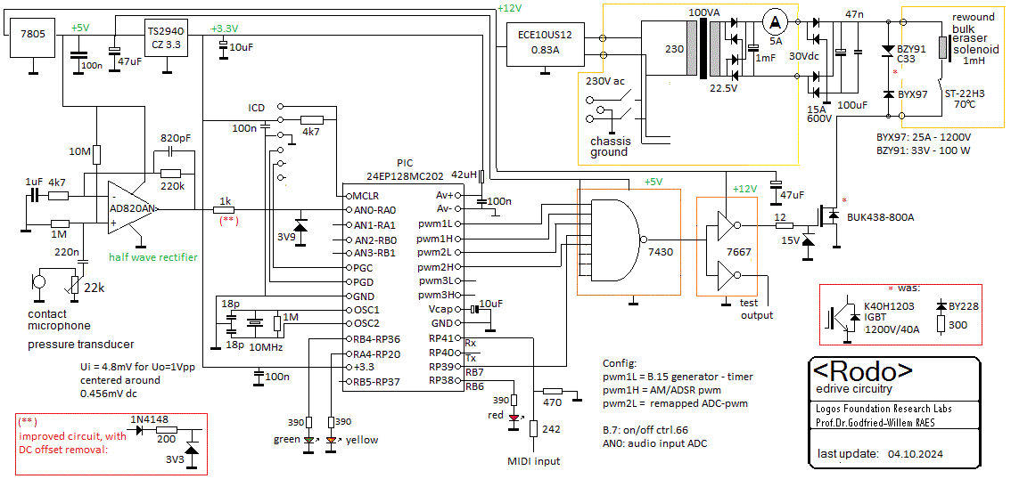 The wiring of the different modules on the <Rodo> chassis needs to undergo
some changes now. We left the firmware running a day and a night and could
not observe any crashes.
- 02.10.2024: Boards reassembled in the robot. On power-up, panel meter shows
higher than 5A current. IGBT failure again... Replaced with an old BUK438-800A
type power mosfet rated for 200W... Further testing performed with a high
power rheostat in series with the e-bow solenoid. The 300 ohm resistor in
series with the BY228 diode over the solenoid gets way too hot. Still, the
exitation level is way too small...
- 03.10.2024: Looks like we have to dig deeply into the smallest details of
inductive loads... The theme of inductors used to cause electromagnetic force
and action is rarely treated in textbooks on electronics. In particular, solenoids
excited with PWM signals are rarely treated. The clamping diode invariably
found placed over the inductor, seems to dissipate more energy than the solenoid
itself...
- 04.10.2024: This circuit may be the good answer to the clamping diode problem:
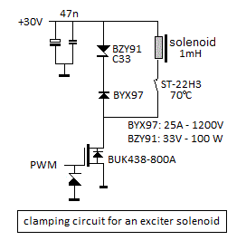 However, it's quite an expensive solution and moreover, it takes quite some
space due to the required heatsink for the power diodes. The core of the solenoid
was designed for a power of 100 VA. Its new coil was wound by us using 2 mm
diameter enameled copper wire. Hence, maximum current allowable in the winding
is 8.5 A. (see copperwire table). The DC
resistance of the coil came out as 2.8 Ohm. The inductance was measured as
1mH at 1kHz. The calculations done on 27.09.2024 still hold.
- 05.10.2024: Test sessions. In-the-land-of-no-return crashes can and do occur
at times... There must be an overflow condition in the radar firmware. In
interactive gesture controlled mode, the current measured through the e-bow
solenoid never seems to exceed 2.5 A. So, that should be safe.
- 06.10.2024: Still, with maximum settings for the duty cycle (#2) and the
drive volume (#7) the heatsinks of the diode assembly can get pretty hot.
No noticeable heat on the drive coil anyhow. Our advice for users would be
to avoid such extreme loud levels for the lowest fifth of the ambitus. At
some point we may revize the firmware, to automate this.
To do:
- - calculation of a parameterized model for the tines
- - construction of alternative rod sets in beryllium copper and phosphor
bronze
- - welding works on the frontal section (distance sensor assembly)
- - replacing the MCP6283 opamp on the radar board with a MCP6023 type, having
a lot less noise.(5.2uVpp versus 2.9uVpp)
- - finalising firmware for the new 24EP PIC microcontrollers
Last update: 2024-10-06
by Godfried-Willem Raes
Further reading by the author on the topic of musical robot design:
Bibliographical references:
Koperdraadtabel voor de berekening
van solenoids
MECHEL, F.P., "Formulas of Acoustics"
OLSON, Harry F. "Music, Physics and engineering"
- ed. Dover, New York (1952), 1967
PHILIPS Semiconductors, "Power Semiconductor Applications"
- ed.:Philips Export B.V.,. Eindhoven 1992
RAES, Godfried-Willem, "Gesture
controlled virtual musical instruments" (1999)
RAES, Godfried-Willem, "Distance
sensing" (2007)
RAES, Godfried-Willem, "BumbleBee"
(2009)
RAES, Godfried-Willem, "Microwave
Gesture Sensing" (2009)
RAES, Godfried-Willem, "A
reminder on comparator design" (2017)
RAES, Godfried-Willem, "Logos @ 50, het kloppend hart van de avant-gardemuziek
in Vlaanderen", ed. Stichting Kunstboek, Oostkamp, 2018
RAYLEIGH, John William Strutt "The Theory of Sound" (2 volumes)
- ed.: Dover Publications Inc., NY, 1945, ISBN 486-60292-3
- een reprint in twee boekdelen van de originele uitgave
uit 1894. (ed.MacMillan Company)
TALUKDAR, S, "Vibration of Continuous Systems",
- ed.:Dept.of Civil Engineering, Indian Institute of Technology Gowahati -
781039.
Technical data sheet, design calculations and maintenance instructions:
Technical data and design elements. Maintenance instructions and replacement
parts.
Technische gegevens, ontwerpberekeningen en instrukties voor onderhoud en demontage:
Solenoids:
- Beaters: Kuhnke Gmbh, type HM157.F.24VDC.100%ED (website: www.kuhnke.de,
e-mail: sales@kuhnke.de). A
copy of their catalogue for linear solenoids containing the data sheets is
available here.
- Dampers: Lucas Ledex, (Saia Burgess) type 195225-229, STA, 9.4V dc @ 100%
- 7Watt, nominal traject 5.1 mm, maximum traject 17.8 mm. Length:39 mm, Plunger:
15.3 g. Total weigth: 87.3 g. DC-resistance: 12.8 Ohm. Maximum power @ 10%
duty cucle: 70 Watt, 11.9 N. Mounting thread: M14 x 1.5.. Lifetime: 25 miljoen
cycli. (= 86 dagen ononderbroken roffelen aan 8 cycli per sekonde).
- Electromagnetic driver: Bulk eraser coil (originally Radio Shack, 100 VA,
220 V). Inductance: 320 mH, DC resistance: 21.27 Ohms.) Rewound in september
2024 with 2 mm enameled copper wire for operation on 20 to 30 V. The new inductance
is 1 mH and DC resistance became 2.8 Ohms.
Tone rods: Material: Aluminum-bronze, Cu Al10 Ni5 Fe4, diameter 8 mm. Ordered
from Demar-Lux bvba.
Cast iron bar: 40 x 40 x 1020, GG25. Ordered from Demar-Lux bvba. http://www.demar-lux.be
- Circuit drawing - pulse boards / damper boards: (download to view at 100%
of size)
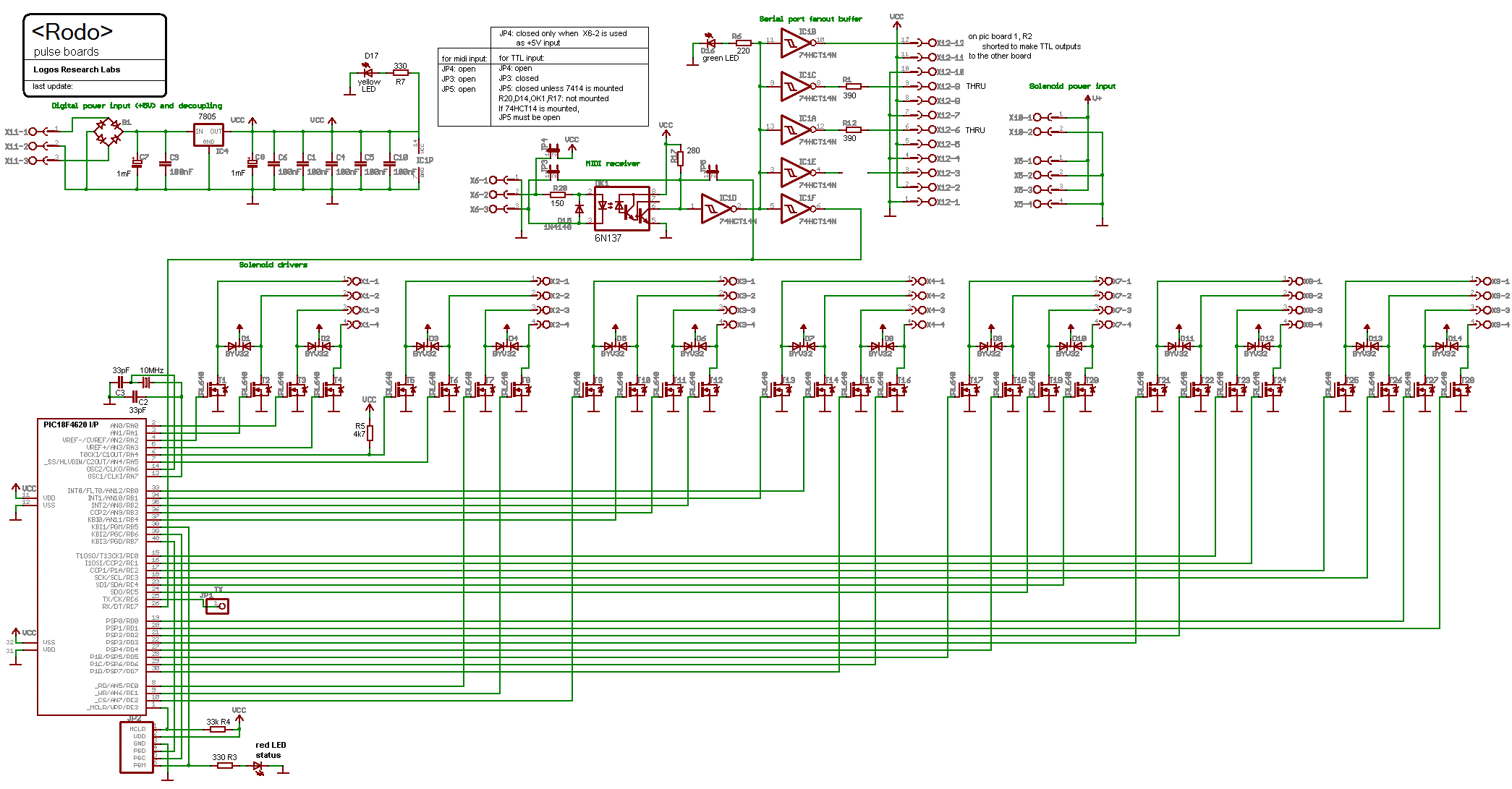
- Source code for the firmware for the beaters notes 48 to 63: http://www.logosfoundation.org/instrum_gwr/rodo/picworks/Rodo_Beaters1.bas.
- Source code for the firmware for the beaters notes 64 to 78:
http://www.logosfoundation.org/instrum_gwr/rodo/picworks/Rodo_Beaters2.bas
- Source code for the firmware for the dampers notes 48 to 63:
http://www.logosfoundation.org/instrum_gwr/rodo/picworks/Rodo_Dampers1.bas
- Source code for the firmware for the dampers notes 64 to 78:
http://www.logosfoundation.org/instrum_gwr/rodo/picworks/Rodo_Dampers2.bas
- Hex dumps and assembly code is available as well.
-
- Power supplies:
- +48 V / 60 V - 150 VA supply (for the beaters)
- +12 V / 25 A supply for the dampers and the lights (300 VA)
- +12 / +5 / +3.3V power (10 W) for the 16-bit PIC board steering the
e-bow mechanism
- + 24 V / 1 A (two separate outputs, 1 A each) for the sensor components
and the LED strips
- +5 V supply for the 18F microprocessors (30 VA). These boards have rectifiers
and regulators on board.
- +30 V / 100 VA supply for the e-bow driver.
- Circuit overview: Version 1.4, 2024
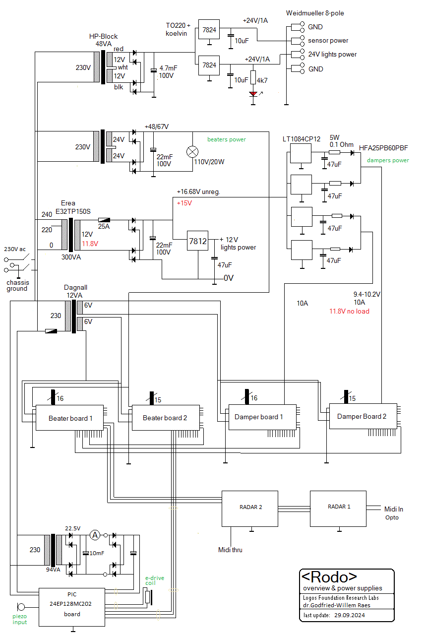
- Obsolete E-drive circuitry (version 2017):

- E-drive circuitry (much improved version 2024):
 Note: The
BUK438-800A power MOSFET used in this version is specified for a power of
200 W.
- Firmware for the e-drive processor
board (For the Proton24 compiler)
-
- Data sheet for the ILP HY2005 amplifier
module (removed in the 2017 version)
- Transformer 94VA 230V - 22.5V ac (2024 version, with rewound e-bow solenoid)
-
Wheels: Ordered from Kaiser + Kraft, Tente, art.nr.95, 415 mm x 60 mm,
polyurethane. (back wheels, with spokes)
- Radar-sensor boards (2): Here is the circuit drawing:
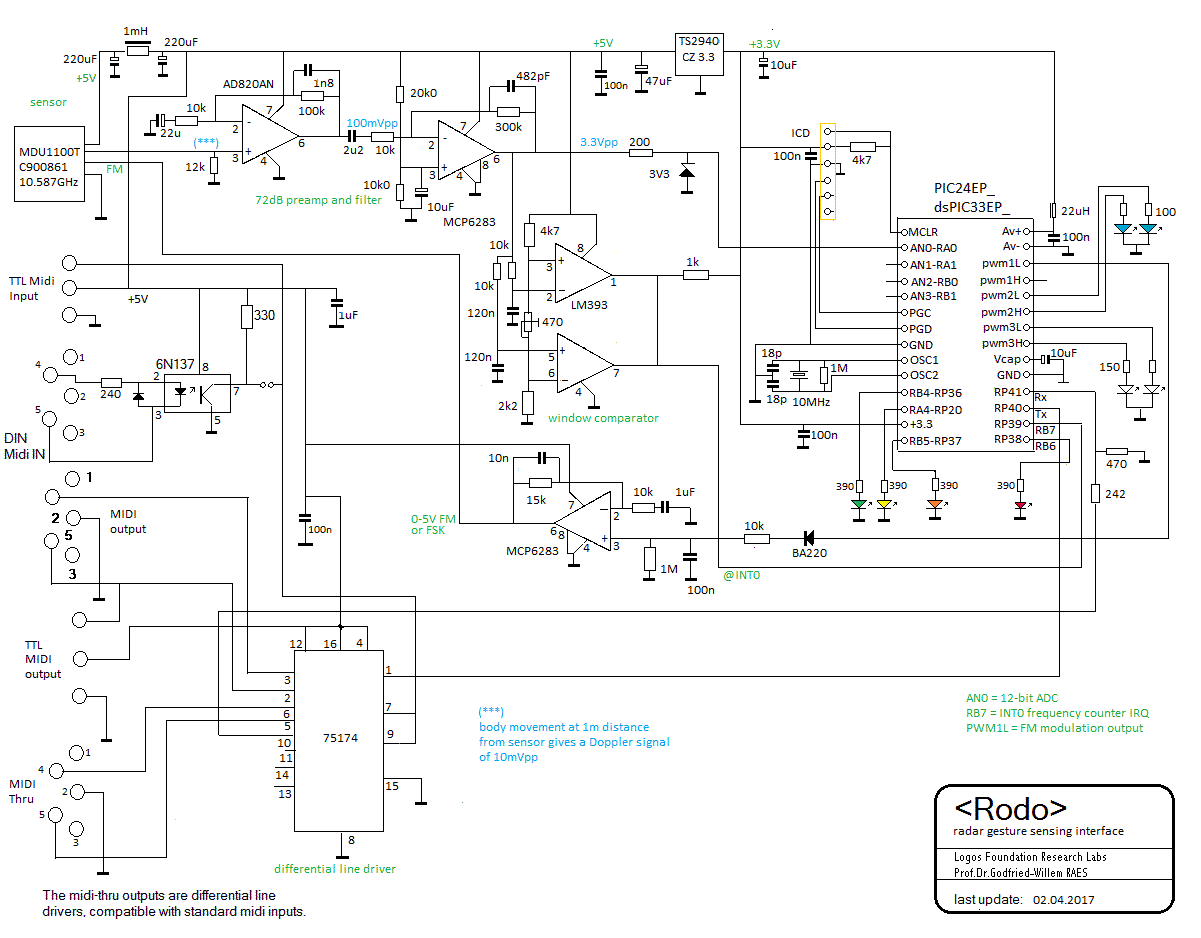 The boards are
almost identical (some corrections made on board 2) but the firmware is slightly
different, as the second board has to merge all incoming midi together with
its own generated midi commands as well as those from the first board. There
are metacompiler statements in the source code to simplify code maintenance
and compilation.
- Firmware for the Radar boards.
(For the Proton24 compiler)
- Front wheel: diameter 200 mm, building heigth 240 mm.
- ARM processor board: AXO board designed by Johannes Taelman. Version Axo
V0.3, 2013.12.10, component mount 90140313. [version 2014 only, board removed
in 2017]
- PIC 24EP128MC202 processor boards, 2017, designed by the author.
- Distance sensor: Honeywell, 944-T4V-2D-1C1-130E. Measurement range: 350mm
to 3500mm. Power supply 24V. Beam angle 8 degrees. Working frequency: 130kHz.
Data sheet and programming manual.
[not yet mounted]
- Radar sensors: 10.587GHz, C900861, MDU1100T .
Data sheet.
- Lights:
- Two LED spotlights on the bottom plate (Yellow, 38 LED's, GU5.3, 1.7W,
BaseTech nr. 574584) (12V)
- Two blue 1W single LED spotlights underneath the frontal part. (12V)
- One white LED light strip (24V, 4.5W) on the backside.
- One white LED light strip (24V/4.5W) on the beater assembly
- Two Red LED spotlight underneath: Kingbright
led clusters. (12V, 2.4W)
- One Red rotating flashlight (24V)
Polystyreen Eigenschappen:
| Notatie |
EPS 60 |
EPS 100 |
EPS 150 |
EPS 200 |
EPS 250 |
| Druksterkte bij 10% vervorming (korte duur) se=10% of CS (10) |
60kPa |
100kPa |
150kPa |
200kPa |
250kPa |
| Lange-duur druksterkte se=2% of CS (2) |
18kPa |
30kPa |
45kPa |
60kPa |
75kPa |
| Buigsterkte sb of BS |
100kPa |
150kPa |
200kPa |
250kPa |
350kPa |
| E-modulus Et |
4000kPa |
6000kPa |
8000kPa |
10000kPa |
12000kPa |
| Afschuifsterkte t |
50kPa |
75kPa |
100kPa |
125kPa |
170kPa |
| Treksterkte st |
100kPa |
150kPa |
200kPa |
250kPa |
350kPa |
| WrijvingscoŽfficiŽnt c |
0.5 |
0.5 |
0.5 |
0.5 |
0.5 |
| WarmtegeleidingscoŽfficiŽnt lD = lR W/m.K |
0.038 K |
0.036 K |
0.034 K |
0.033 K |
0.033 K |
| Diffusieweerstandsgetal m |
20 |
30 |
40 |
60 |
90 |
| Vochtopname bij onderdompeling % v/v |
5.0 |
4.0 |
3.5 |
3.0 |
2.0 |
| Lineaire uitzettingscoŽfficiŽnt a m/m |
7.10-5 |
7.10-5 |
7.10-5 |
7.10-5 |
7.10-5 |
| Warmtecapaciteit C J/kg K |
1450 |
1450 |
1450 |
1450 |
1450 |
| Temperatuurbestendigheid (min/max) T |
-180 +80 |
-180 + 80 |
-180 +80 |
-180 +80 |
-180 + 80 |
Robody Pictures with <Rodo>
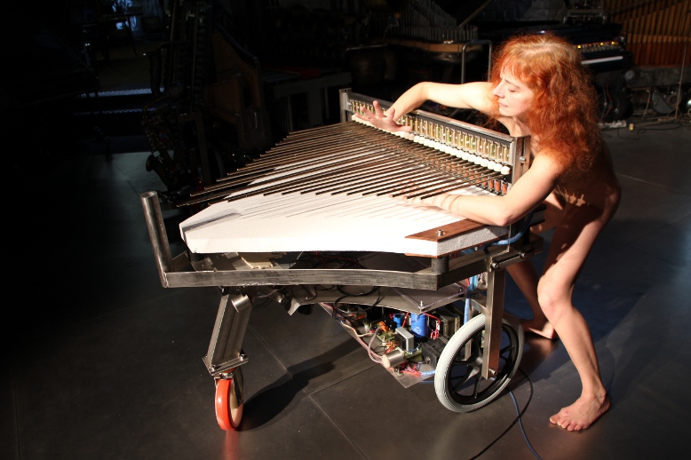


 With: f= frequency in
Hz, L= length of the rod, k=diameter of the rod, Q= modulus of elasticity, r=
density of the material. (Olson, p.76)


 Spoke wheels ordered from Kaiser+Kraft. (415 mm x 60 mm, 120 Euro each).

 HY2004 amplifier module replaced. Measurements: with 160V ac on the output
transformer and over the driven electromagnet, the HY2004 gets pretty hot.
The amp output is delivering 23.5V to the transformer then, so it ought to
be well within specs... (66V pp output, that is).
 Start of the design of an appropriate PCB. A very large heatsink is an absolute
requirement here. ARM board firmware for the sensor components (Axo platform)
by Kristof Lauwers and Johannes Taelman will no longer be needed, as we will
remove the Axo board.

 Yet to be tested.
 Measurements performed with the Tektronix TDS2024C:at a movement velocity
of ca. 1 m/s we measure downgoing pulses on the comparator outputs at about
140 Hz. Pulse lenghts are in the order of 7.2 ms. This is in line with what
we expected to get from the datasheet: 1 m/s should give a Doppler shift of
70 Hz. If we set the maximum movement speed to 5 m/s, the shortest valid pulses
we can expect would be 1.5 ms. So, in the firmware handling the external interrupt,
we can disregard everything shorter as being a glitch. At 10 cm/s we could
measure the longest pulses, in the order of 72 ms. Below that speed, the circuit
looses sensitivity very fast because of the high pass filter in the pre-amp
circuit, in particular the 2.2uF capacitor.
 Firsty tests with the radar 1 board connected to <Rodo>. The 'RadaRodo'
piece still needs quite some refinements. The midi-merge functions look like
working o.k. Controllers #70 to #73 added in the Radar firmware.

 The strange observation is that simply touching anything connected to pin
2 of the 555 timer chip, triggers the timer. Thus, we do not even need the
microswitch...
  The wiring of the different modules on the <Rodo> chassis needs to undergo
some changes now. We left the firmware running a day and a night and could
not observe any crashes.
 However, it's quite an expensive solution and moreover, it takes quite some
space due to the required heatsink for the power diodes. The core of the solenoid
was designed for a power of 100 VA. Its new coil was wound by us using 2 mm
diameter enameled copper wire. Hence, maximum current allowable in the winding
is 8.5 A. (see

 The boards are
almost identical (some corrections made on board 2) but the firmware is slightly
different, as the second board has to merge all incoming midi together with
its own generated midi commands as well as those from the first board. There
are metacompiler statements in the source code to simplify code maintenance
and compilation.