<Microwave Gesture Sensing>
a doppler radar based gesture measurement system capable of delivering positional information
by
dr.Godfried-Willem Raes
postdoctoral
researcher
Ghent University College & Logos Foundation
2009
![]()
This technical note is a continuation of reports on many earlier designs for gesture sensing apparatus using both sonar and radar technologies. References to earlier designs are given in the reference section below. (1)
Doppler based microwave devices can be used to make pretty good movement sensors with a range from very nearby to about 20 meters. The transceivers output a demodulated signal (some types offer quadrature outputs directly) whose frequency is proportional to the detected target speed and angle of movement whereas the amplitude is proportional to distance and amount of moving body surface. As to human bodies, the most reflective surface is the naked skin. We performed measurements showing that a pullover gives a damping in the order of at least 12 dB, thus reducing the resolution of the sensor effectively with a factor 4 or worse. Hence our advise to always perform measurements naked with any version of this invisible instrument, if you want optimal resolution.
For the project we are reporting here, the following devices are examined:
MDU1100 (Microwave Solutions Ltd.): X-band, operating microwave frequency is specified at 10.587 GHz. Transmitted RF power <=15 mW. IF output impedance: 200 Ohm. DC offset on the IF output: 150mV. Antenna pattern: 72° horizontal, 36° vertical.
MDU2400 (Microwave Solutions Ltd).: K-band, operating microwave frequency 24.2 GHz. Transmitted RF power 7dBm EIRP. Antenna pattern: 72° horizontal, 18° vertical.
RSM1700 (Conrad), IPM170 (Microsense), Amiwima DRM-24 (Allsat Gmbh) devices operating around 24.125 GHz. This type has a microwave output power of 15 dBm (EIRP), temperature drift is specified as 1MHz/°C. The antenna pattern has a conical opening angle of 70°. These K-band devices are mostly used for adaptive cruise control applications in motor vehicles.(3)
Doppler formula:
fd = 2 v fo / c
so, after solving the device specific constants we get for the 10.587GHz device:
fd = 70.58 v (Hz) for the 10.587 GHz devices and for the 24 GHz device: fd = 160 v (Hz)
This holds for movements in line with the axis of the sensor. For other angles, the formula becomes:
fd = 70.58 v cos(a), resp. fd = 160 v cos(a)
Where a is the angle between the movement and the axis of the sensor. The circuit is optimized for the movement velocity range between 2.6 cm/s and 5 m/s, the highest speed conforming to our measurements with regard to the movement speeds of the human body parts. (2) When we sample the signals at 1024 S/s, the highest detectable frequency would be at 10 GHz, 512 Hz, so well above the highest frequency of interest, 353 Hz (the doppler frequency for a movement speed of 5 m/s), conforming to the Nyquist theorem. At 24 GHz, 800 Hz becomes the highest expectable frequency thus requiring a sampling rate of 2048 S/s.
Signal amplitudes are inverse proportional to the square of the distance to the antenna and directly proportional to the size of the surface of the moving body. The detection range for these devices is variable from 0.2 to 10 meters. Noise limits the range and the resolution of the unit. Since we want the device to operate in real time, there is no way to resolve signals below or around the inherent noise level of the devices. The polar sensitivity, according to the datasheet, shows an opening angle of 72° in a horizontal plane and 36° in a vertical plane (10 GHz device), or 70°, conical, for the 24 GHz devices. This almost dictates an application with four devices set up on the vertexes of an imaginary tetrahedron, a setup we have found optimal in many earlier experiments.
The formulas given above are enough for a first approximation and insight but obviously they are way too far simplifications of the reality of gesture capture. In order to capture characteristics of gesture, a spectrum analysis should be performed on the signal at a rate of at least 100 times a second. The interpretation of the spectral data thus obtained allows for a good classification of gesture characteristics.
The first prototype front-end we designed for the cheap 24 GHz transceiver was build according to following circuit:
The first stage after a DC blocking cap (1uF) designed for a low frequency limit of 1 Hz (required since the DC level on the output varies in a range of +/-300 mV), is a very low noise preamp with 40 dB gain. The 680 pF cap in the feedback loop creates a roll off at 1 kHz. This stage is followed by a 5th order passive butterworth low pass filter designed again for a cut off frequency at 1 kHz. Practical values for the resistors became 390 Ohms and for the caps 220 nF+33 nF (2 times) and 820 nF. The last stage is again a 40 dB inverting amp, wherefore we choose the LF356 because of its capacity to drive large capacitive loads such as presented by cables. The power supply should be of a tracking type and dimensioned for at least 75 mA (+15 V) and 15 mA (-15 V). Pay care to mains frequency filtering as well as noise performance. The circuit as shown gives very good signal/noise ratio and an output signal thats calculated for 3 Vrms output, but this can swing (and clip...) against the supply rails if the movements are performed too close to the sensor. Make sure you ADC device handles this well enough or else, provide a simple compressor-limiter for the output.
The first realized version can be seen on this picture: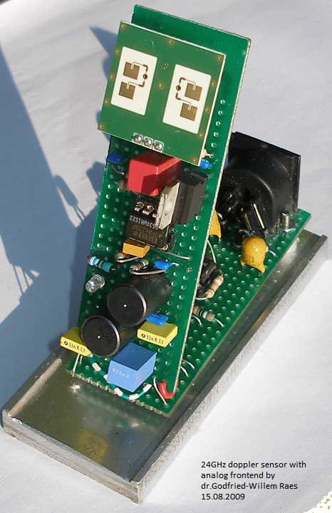 As can be seen we spread the circuit over two different pieces of experimenting
circuit board such that the board carrying the sensor module can be placed under
the required 72 degree angle, as dictated by a tetrahedral setup. The sensor
to be placed on top of the tetrahedron setup got a different design and looks
like:
As can be seen we spread the circuit over two different pieces of experimenting
circuit board such that the board carrying the sensor module can be placed under
the required 72 degree angle, as dictated by a tetrahedral setup. The sensor
to be placed on top of the tetrahedron setup got a different design and looks
like: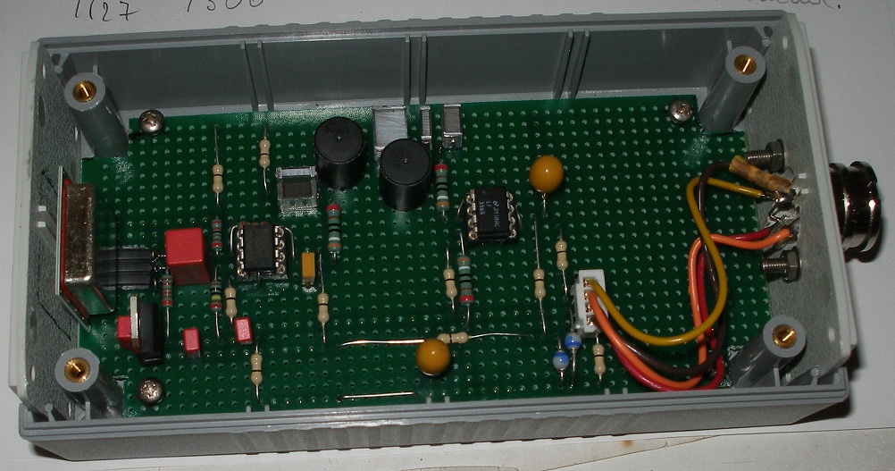
Four of these sensors were build in the first experiment. To connect all four to the data acquisition boards, another circuit with buffers and adjusting potmeters was constructed according to following straightforward circuit drawing:
 We
implemented 4 audio outputs as well (with an attenuator, since the 10V pp signal
would certainly saturate the inputs) such as to make connection to standard
PC audio card inputs possible as well. The realized board looks like:
We
implemented 4 audio outputs as well (with an attenuator, since the 10V pp signal
would certainly saturate the inputs) such as to make connection to standard
PC audio card inputs possible as well. The realized board looks like: 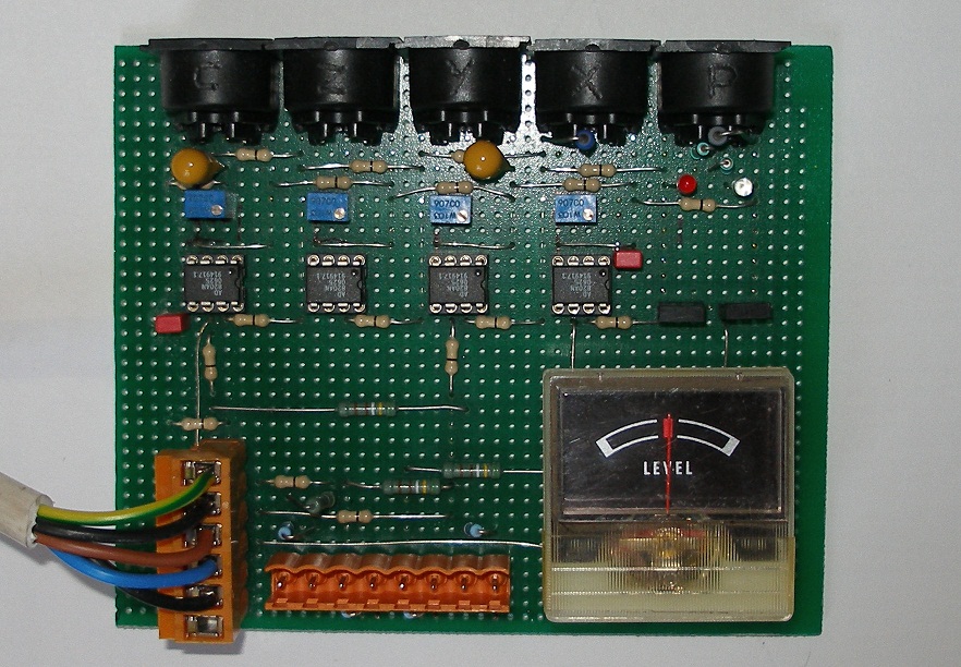
The objection one often makes against the use of Doppler radar devices such as the one described above, is that neither the position of the movement nor the absolute speed can be determined, However, with the devices we are discussing here, it becomes very well possible to determine the distance to the moving body with quite good resolution. In order to achieve this, the carrier frequency of the microwave signal has to be frequency modulated. By comparing the phase of the modulating signal with the modulated signal found back in the reflection, it is possible to measure the distance to the moving target. If we take the maximum range for the radar as 10 m, than the over-and-back distance is 20 m and the time lapse involved <= 66 ns. Remind you that this is radar and the waves propagate at the velocity of light. If we want the phase angle to cover 90° for full range, we can calculate the required modulation frequency as 1/266 ns = 3.750 MHz. We assume sinusoidal modulation here, for this minimizes the occurrence of unwanted sidebands. The MDU1100 devices have a frequency modulation input with a range of 4 MHz (0-5 V modulation), thus capable of fulfilling our calculated requirement. Note that even the transceivers without such a provision can be used with frequency modulation, by modulating their operating voltage. We have tested this with the RSM1700 devices. Achievable modulation depth will we smaller though. A multiplier or phase comparator can be used to output a distance proportional signal directly. This signal is inherently low frequency. The frequency modulation of the carrier however does induce extra jitter on the Doppler signals, but since the frequency deviation of 3.75 MHz is only 0.37 promil versus the carrier frequency, the induced Doppler error remains very reasonable at ca. -54 dB.
For full 3-dimensional gesture sensing, we use four of these circuits. To connect the outputs from these 4 devices to 8 A/D channels of a National Instruments USB data acquisition device, we designed an adapter board including some analog signal conditioning. Preamplification such as to bring the voltage range within 20 Vpp as well as low pass filtering using Butterworth 5th order filters. We selected a NI-USB-6210, 16 channels, 250 kS/s, 16 bit type for the link to the PC. The adapter board also houses a linear stabilized power supply for the transducerboards. These require 5 V and draw about 60 mA each. Standard 5pole 180° DIN connector cabling is used for the interconnections.
As we noted in earlier publications based on our research into microwave radar devices (1), the sensors used here can also be disturbed by ionizing sources in their neighborhood and range of sight. So the use of this equipment together with CRT's, TV-sets, TL-light, mercury vapor bulbs, our own digital loudspeakers, welding equipment, sodium vapor bulbs within a range of 10 meters around the setup should be discouraged. Another consideration is worth mentioning: the boards should be placed at least a full wavelength (ca. 3 cm, for these devices) away from any grounded object, since the presence of such objects sucks away all radiated energy from the antennas. In some applications, where gasdischarge lights are permanent fixtures, it may be required to implement a selective combfilter in software, tuned to the mains frequency and its harmonics. Listening to the output signal will learn you a lot about the nature of disturbances. It's more instructive than looking at the waveform on an oscilloscope.
This project as for now, is in the research phase and further reports will follow. Material problems (we have no research funds...) as well as time constraints (we have no assistance for hardware development...) are the main source of frustration.
![]()
Software
The software consists of two levels: a first level, a thread in its own, samples the signals from the transducers at the required sampling rate and processes this data such that we get access to following parameters (for 10 GHz devices, for the 24 GHz the values have to be doubled):
The prime signals undergo three downsampling stages:
For gesture analysis, the three contexts are always taken into account. The mechanism in use to perform classification of gestural data is based on fuzzy logic. For the gesture classes and their description, we refer to earlier publications on the subject matter. Note that for the 24 GHz transceivers, the sampling rates have to be doubled and the latency will be more twice as small. Because of the quite heavy math involved in the data analysis, it it strongly advised to make use of a multiprocessor PC and a full multithreaded software design. This is also supported by the libraries for the NiDAQ device provided by National Instruments. The required declaration files for NiDAQmx to be used with the infamous PowerBasic compiler can be obtained from us on simple demand.
In principle it ought to be possible to use these devices without data acquisition hardware by connecting them to the 2-channel audio input of a regular PC. However, note that the latency will be higher and that -for most audio hardware in PC's- the resolution for slow movements will be limited by the standard high pass filter on the inputs, normally specified as 20Hz. The audio data can be retrieved using the standard functions in the Win API, however, downsampling and data processing has to be handled in your own code. It shouldn't be too difficult to get it all done in Pure Data. People at Logos working on this are Hans Roels, Yvan Vander Sanden and Kristof Lauwers.
Dr. Godfried-Willem Raes
Notes:
(1) This project is part of the ongoing research of the author in gesture controlled devices over the last 35 years. Earlier systems, based on Sonar, Radar, infrared pyrodetection and other technologies are fully described in "Gesture controlled virtual musical instrument" (1999) as well as in his doctoral dissertation 'An Invisible Instrument' (1993). Artistic productions and compositions using these interfaces and devices have been: <Standing Waves>, <Holosound>, <A Book of Moves>, <Virtual Jews Harp>, <Songbook>, <Slow Sham Rising>, <Gestrobo>, <Quadrada>, <Technofaustus> , <Butoh> etc.
(2) As of august 16th 2009 the world record for running in the 100 m competition is fixed at 9.58 s. This corresponds to a movement speed of 10.52 m/s or 37.8 km/h. Needless to say that such speeds are not encountered amongst 'normal' people, even not when they get involved in the wildest forms of dancing.
(3) For adaptive cruise control in cars, the frequency band of 77 GHz has been proposed and investigated since 1998. However, these transceivers are a lot more expensive and furthermore almost impossible to obtain. As soon as we can get our hands on such devices, we will report on their usability in the context of human motion detection and analysis.
(4) Complete source code for all math involved is available on the web at http://www.logosfoundation.org/gmt/gmt_dev/g_h.bas. The compiled library is called g_nxh.dll and can also be used with C compilers.
Bibliographical references:
First published on the web: 02.08.2009 by dr.Godfried-Willem Raes
Last update:2009-09-08