|
Musical Robot |
|
<Tinti> automated tintinabuli dr.Godfried-Willem RAES 2015 |
|
Musical Robot |
|
<Tinti> automated tintinabuli dr.Godfried-Willem RAES 2015 |
<Tinti>
When developing our <Zi> robot we were confronted with a big failure,
as the plucking mechanism we constructed for the strings didn't work properly
at all. The bidirectional solenoid assemblies used had too little force to properly
pluck our strings. Thus, we designed a completely new mechanism for the <Zi>
robot, leaving us with an after all nicely build and fully working plucking
assembly that became completely obsolete. This gave us the idea to use it for
a completely different robot, dictating the use of bidirectional solenoids and
requiring only very low forces. By the nature of the mechanism, it ought to
activate sound objects that require shaking. The shaking principle was already
used in quite a few earlier robots such as <Psch>, <Klung> and the
windchimes in <Thunderwood>. Thus we got the idea to use the mechanism
to shake extremely high pitched tiny cast bells, tintinabuli. This is completely
unrelated to the infamous super-kitsch reactionary composer Arvo Pärt who
misused this latin word to refer to his trivial and redundant triad based composition
style.
Here is a first prototype plucker, made using a solenoid assembly from Syndyne: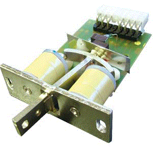 These
components are normally used as register knobs on pipe organs with electromagnetic
registration. We contacted the factory in order to obtain these components with
a straight anchor, as this would be much easier to attach the plectra. We made
the plucker assembly for a maximum of 38 strings, welded from stainless steel.
The electronics require twice as many pulse/hold circuits and thus we needed
no less than six driver boards and microprocessors. These boards are the same
as the ones we developed for our player piano, <Qt>, <Bomi> and
a few more robots where velocity control combined with a hold function was needed.
The hold function is however not realy required for the <Tinti> robot,
but we kept the electronic hardware as it worked nicely. The boards have a maximum
of 14 outputs each and taking into account that here we need two outputs for
each solenoid, we need one board for every seven dual solenoid mechanisms.
 The
picture shows the mechanism with associated electronics before wiring.
The circuit for the control of this prototype bidirectional solenoid assembly for each of the solenoid assemblies is given below:
 It took us
more than two months to finish this prototype mechanism.
The solenoid order and lay out looks like: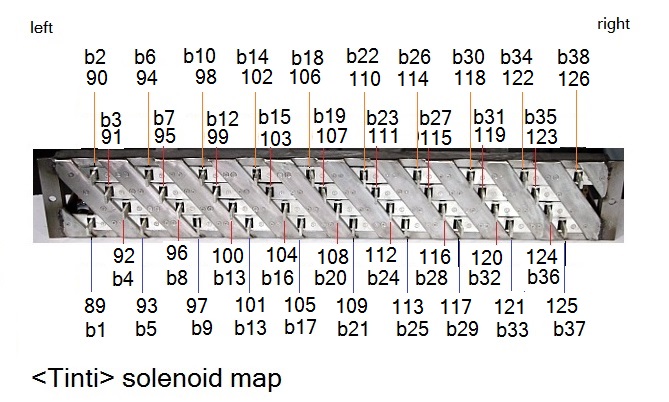 Obviously, if we had to design it for a bell shaking mechanism from the beginning
on, we would certainly not have made it this complicated. The entire mechanism
now rests on two threaded pieces of 20 x 10 x 150 stainless steel, secured with
two M8 bolts. It can easily be taken off for adjustments, however the connectors
should first be loosened and the power turned off.
A nice and original feature of this robot is that the sounds it produces are extremely high pitched and their spectral components extend well into the ultrasonic range. This opened a wealth of musical possibilities when used in combination with our ultrasound based invisible instrument technology. In fact, the sensors we developed for this instrument capture the ultrasonic components of the tiny bells very well and, due to the demodulation circuitry, can be brought into the audible range and even be modulated through gesture and movement. Quite magic in fact. Thus we decided to give this robot some build-in ultrasonic technology. First of all, we used the PIC microprocessor on the midi-hub board to generate ultrasonic frequencies in the range 16kHz to 38kHz. The frequency can be modulated in real time using pitch bend commands. The amplitude of the emitted ultrasound can be controlled with controller #8. A problem we had to solve was finding powerfull ultrasonic transducers, as the usual 40kHz types have a way too small frequency range or bandwidth. Thus we came across cheap piezo tweeters made by Kemo (type P5123) with a frequency range specified up to 45kHz. Of course, we couldn't go without measurement, and indeed they have output in that range up to the specified frequency but their output is very far from linear. The response curve shows peaks and dips in the range +12dB to -12dB and the frequencies at which these dips and peaks occur are different for each individual tweeter... This obviously renders linearisation through circuit design a near mission impossible. So we just have to live with it. To compensate this deficiency, we added two piezo-tweeters with paper cones and a much higher efficiency left and right under the tintinabuli. The Kemo speaker was placed very near to the ultrasound microphones. If this ultrasonic feature is enabled on the <Tinti> robot, the audible result is that all difference tones between the carrier frequency and the ultrasonic components of the tintinabuli become audible through the build-in speaker. Although this robot has indeed a loudspeaker, it should not be considered an electronic instrument at all, as all sound produced is still inherently acoustic. By modulating the carrier frequency, pitch shifts of the tintinabuli sounds become possible. The optimum carrier frequency setting and range is different from bell to bell. A look-up table is given in the users manual. The effect is quite mesmerizing.
A final remark: as this robot can emit ultrasonic frequencies it is likely to cause interference with our ultrasound based gesture sensing technology. So composers should make sure they test their concept thoroughly before attempting to use <Tinti> in a gesture-interactive environment. Composers that want to experiment with it are advised not to use the internal ultrasound emitter in this case, but use the emitter that is part of the invisible instrument itself instead. This will work without interference, but pitch shifts are impossible this way. If the ultrasound frequency on Tinti is kept around 20kHz, interference should be at a minimum. 20kHz is obtained by setting CC31 to 27, pbmsb to 0 and pblsb to 88. If our radar equipment (PIC-Radar, Quadrada etc...) is used at the other hand, no interference can occur as its working principle is based on microwaves and not on sound.
Only when integrated in the context of our M&M robot orchestra with its wealth of varied sensor systems allowing full interactivity with gesture and audio, this automate will become a true robot. That's after all were its destination is to be sought.
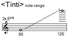 This is the ambitus
for the instrument . [for now, note 127 is missing].
Midi channel: fixed to 11 (counting 0-15).
Note Off: Implemented for all notes in the range. On reception of a note off
command, the anchors return to their power-off condition.
Note On: Implemented for notes in the range. Velo-byte is used for the striking force. The range is rather limited. The lights are also mapped on notes, but make use of a range outside the normal range of the robot.They are mapped on notes 12 to 16.
Key pressure: can be used to individually set the shaking repetition rate for each bell. The slowest repetition rate is 1 second, the fastest 30 shakes a second. The scaling is logarithmic.
Controller 7: Volume control for the ultrasonic receivers and amplification.
Controller 8: sound pressure level for the ultrasonic carrier wave. This works
by PWM on the carrier wave (range 0-50%). The effect is not spectacular, but
using lower settings helps to reduce the spikes in the bell sounds. With a setting
to maximum, the duty cycle will be 50% and the waveform symmetrical and reasonably
sinusoidal..
Controller 30: sets the repetition rate for all components that have auto-repeat implemented (tintinabuli as well as lights).
Controller 31: can be used to shift the frequency range of the carrier frequency in chromatic steps as shown in this table:
| Value | base frequency | midi note | note name |
| < 12 | 21096 Hz | 136 | E |
| 12 | 8372 Hz | 120 | C |
| 13 | 8870 Hz | 121 | C# |
| 14 | 9397 Hz | 122 | D |
| 15 | 9956 Hz | 123 | Eb |
| 16 | 10548 Hz | 124 | E |
| 17 | 11175 Hz | 125 | F |
| 18 | 11840 Hz | 126 | F# |
| 19 | 12544 Hz | 127 | G |
| 20 | 13289 Hz | 128 | G# |
| 21 | 14080 Hz | 129 | A |
| 22 | 14917 Hz | 130 | Bb |
| 23 | 15804 Hz | 131 | B |
| 24 | 16744 Hz | 132 | C |
| 25 | 17739 Hz | 133 | C# |
| 26 | 18794 Hz | 134 | D |
| 27 | 19912 Hz | 135 | Eb |
| 28 | 21096 Hz | 136 | E |
| >28 | 21096 Hz | 136 | E |
If any controller value setting in the range 12 to 27 is send, the blue LED on the hub-board will light up. The actual frequency generated will always be the base frequency with the 14-bit value send with the pitch shift command added. The default value for this controller is 28. Note that with lower base frequencies (below 24 or 16744Hz), a high piercing sound will become audible from the ultrasound emitters! The formula for calculating the frequency of the emitted sound is: f = (8372 * 2^((CC31 - 12)/12)) + (pbmsb * 128) + pblsb, wherein CC31 is the setting for controller 31 within the limits 12 to 28, pbmsb the 7-bit value sent with the pitchbend command and pblsb the low 7-bit value of the pitchbend command.
Controller 66: Robot on/off switch. Sending this controller with value zero will power down the robot and reset all controllers to their default value.
Controller 123: All notes off, preserving controller settings.
Pitch bend: used to modulate the ultrasonic carrier wave. (all 14 bits are used as a unipolar unsigned 14 bit value). The frequency can be controlled between basefrequency (by default 21096 Hz) and basefrequency + 16384. So the upper limit for the ultrasonic frequency is 37480Hz.
Lookup table for good ultrasound carrier frequency settings and ranges for each individual bell:
| note | frequency | msb | lsb | ctrl 31 |
| 89 | 23336 Hz | 17 (16-19) | 64 | 28 |
| 90 | 29352 Hz | 64 (62-66) | 64 | 28 |
| 91 | 22312 Hz | 9 (0-18) | 64 | 28 |
| 92 | 22312 Hz | 9 (0-17) or 124-127 | 64 | 28 |
| 93 | 33576 Hz | 97 (95-127) | 64 | 28 |
| 94 | 22312 Hz | 9 (0-18) | 64 | 28 |
| 95 | 21928 Hz | 6 (0-12) | 64 | 28 |
| 96 | 36520 Hz | 120 (107-127) | 64 | 28 |
| 97 | 22440 Hz | 10 (0-20) | 64 | 28 |
| 98 | 22568 Hz | 11 (5-18) | 64 | 28 |
| 99 | 22440 Hz | 10 (3-17) | 64 | 28 |
| 100 | 22312 Hz | 9 (3-14) | 64 | 28 |
| 101 | 22184 Hz | 8 (3-14) | 64 | 28 |
| 102 | 22440 Hz | 10 (0-19) | 64 | 28 |
| 103 | 37032 Hz | 124 (122-127) | 64 | 28 |
| 104 | 22824 Hz | 13 (6-20) | 64 | 28 |
| 105 | 22440 Hz | 10 (1-20) | 64 | 28 |
| 106 | 22440 Hz | 10 (0-19) | 64 | 28 |
| 107 | 22056 Hz | 7 (6-9) | 64 | 28 |
| 108 | 22312 Hz | 9 (0-17) | 64 | 28 |
| 109 | 37032 Hz | 124 (120-127) | 64 | 28 |
| 110 | 22696 Hz | 12 (6-18) | 64 | 28 |
| 111 | 22056 Hz | 7 (6-9) | 64 | 28 |
| 112 | 22824 Hz | 13 (6-20) | 64 | 28 |
| 113 | 22952 Hz | 14 (4-24) | 64 | 28 |
| 114 | 22440 Hz | 10 (0-19) | 64 | 28 |
| 115 | 31912 Hz | 84 (82-87) or 0-20 | 64 | 28 |
| 116 | 22184 Hz | 8 (0-16) | 64 | 28 |
| 117 | 21544 Hz | 3 (0-6) | 64 | 28 |
| 118 | 24360 Hz | 25 (19-30) or 0-15 | 64 | 28 |
| 119 | 15365 Hz | 3 (0-32) | 64 | 22 |
| 120 | 23336 Hz | 17 (15-19) | 64 | 28 |
| 121 | 23464 Hz | 18 (16-20) | 64 | 28 |
| 122 | 22184 Hz | 8 (0-16) | 64 | 28 |
| 123 | 22952 Hz | 14 (10-18) | 64 | 28 |
| 124 | 35752 Hz | 114 (100-127) | 64 | 28 |
| 125 | 35880 Hz | 115 (103-127) | 64 | 28 |
| 126 | 21928 Hz | 6 (0-12) or 80-95 or 101-127 | 64 | 28 |
Technical specifications:
Design and construction: dr.Godfried-Willem Raes
Collaborators on the construction of this robot:
Music composed for <Tinti>:
Pictures taken during the construction in our workshop (in chronological order):
Robodies picture with <Tinti>:
| Back to Main Logos page:index.html | To Godfried-Willem Raes personal home page... | To Instrument catalogue |  |
Construction & Research Diary:
 And this is the PCB, real size:
 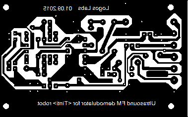 The
LDR-LED combination, making an optor, is an integrated component by Silonex,
Type nr. NSL-32SR3. The dark resistance of the LDR is >2.8MOhm. Thus the
dynamic range will be somewhat larger than 60dB. Here is a
link to the datasheet.
The
LDR-LED combination, making an optor, is an integrated component by Silonex,
Type nr. NSL-32SR3. The dark resistance of the LDR is >2.8MOhm. Thus the
dynamic range will be somewhat larger than 60dB. Here is a
link to the datasheet.| midi note | note name | base frequency | CC31 | pb msb | pb lsb |
| 120 | C | 8372 Hz | 12 | 0 | 0 |
| 121 | C# | 8870 Hz | 13 | 0 | 0 |
| 122 | D | 9397 Hz | 14 | 0 | 0 |
| 123 | Eb | 9956 Hz | 15 | 0 | 0 |
| 124 | E | 10548 Hz | 16 | 0 | 0 |
| 125 | F | 11175 Hz | 17 | 0 | 0 |
| 126 | F# | 11840 Hz | 18 | 0 | 0 |
| 127 | G | 12544 Hz | 19 | 0 | 0 |
| 128 | G# | 13289 Hz | 20 | 0 | 0 |
| 129 | A | 14080 Hz | 21 | 0 | 0 |
| 130 | Bb | 14917 Hz | 22 | 0 | 0 |
| 131 | B | 15804 Hz | 23 | 0 | 0 |
| 132 | C | 16744 Hz | 24 | 0 | 0 |
| 133 | C# | 17739 Hz | 25 | 0 | 0 |
| 134 | D | 18794 Hz | 26 | 0 | 0 |
| 135 | Eb | 19912 Hz | 27 | 0 | 0 |
| 136 | E | 21096 Hz | 28 | 0 | 0 |
| 137 | F | 22350 Hz | 28 | 9 | 102 |
| 138 | F# | 23680 Hz | 28 | 20 | 24 |
| 139 | G | 25088 Hz | 28 | 31 | 24 |
| 140 | G# | 26578 Hz | 28 | 42 | 106 |
| 141 | A | 28160 Hz | 28 | 55 | 24 |
| 142 | Bb | 29834 Hz | 28 | 68 | 34 |
| 143 | B | 31608 Hz | 28 | 82 | 16 |
| 144 | C | 33488 Hz | 28 | 96 | 104 |
| 145 | C# | 35478 Hz | 28 | 112 | 46 |
TO DO:
| (Terug) naar logos-projekten: | Terug naar Logos' index-pagina: | Naar Godfried-Willem Raes personal homepage... | Naar katalogus instrumenten |  |
M&M orkest |
Last update: 2023-11-27 by Godfried-Willem Raes
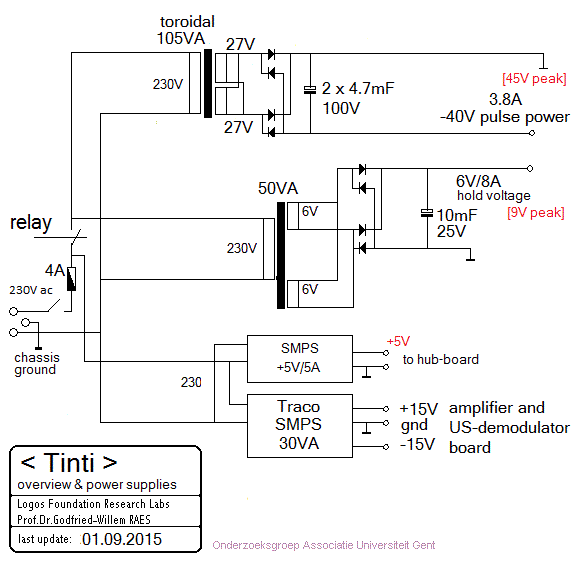
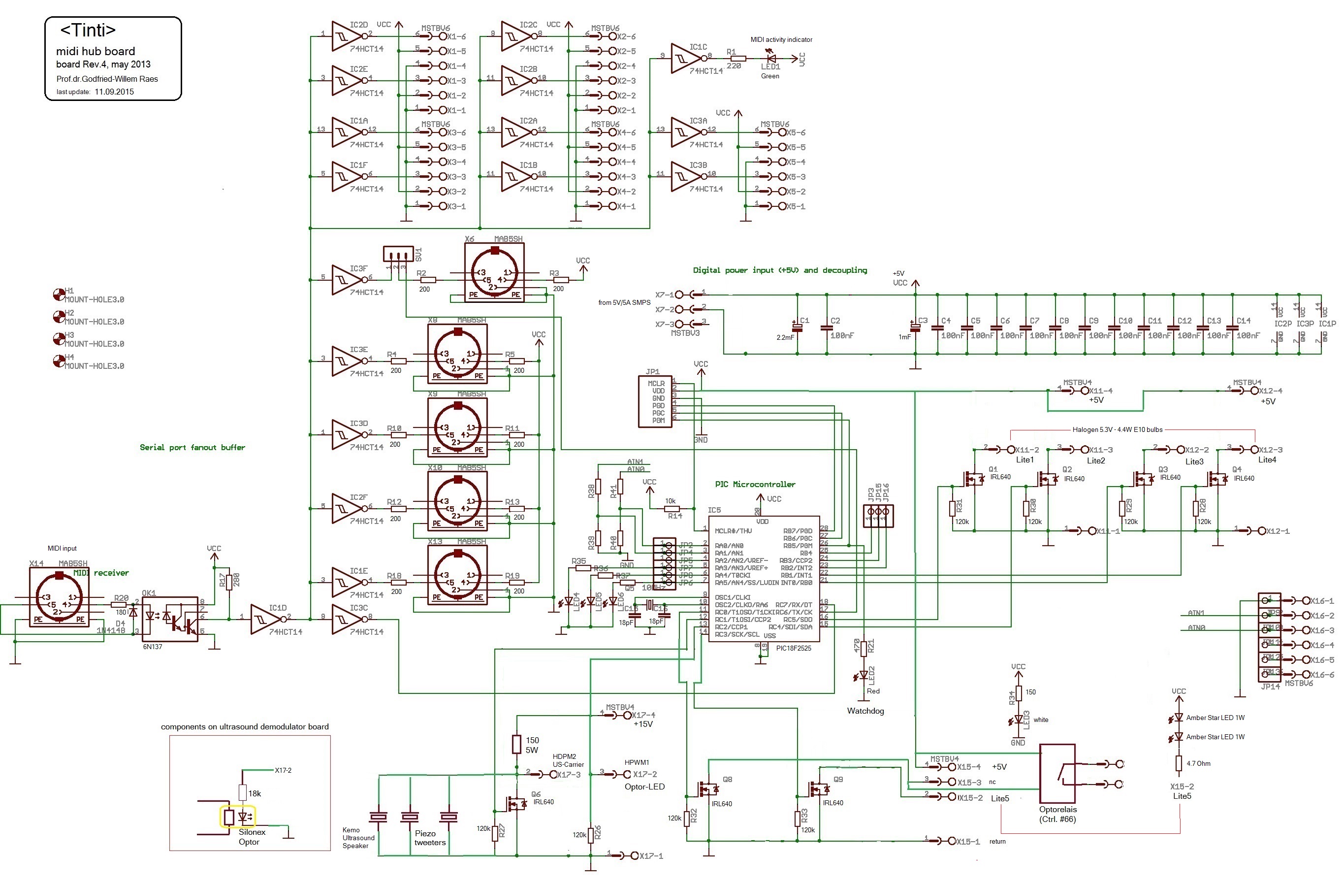
The following information is not intended for the general public nor for composers wanting to make use of our <Tinti> robot, but is essential for maintenance and servicing of the robot by our collaborators. It also might be usefull as a source of inspiration for people that want to undertake similar projects. Feedback is mostly welcomed.
Technical drawings, specs and data sheets:
Power supplies:
Wiring & circuit details midihub board:
Circuit details solenoid driver boards:
Board 1:
| bell nr | board output | connector pin |
midi mapping |
remarks | PIC pulse pin | PIC hold pin |
| - | 1 | 2 | note 19 | hold only - lite | 4 = RA1 | 3 = RA2 |
| - | 2 | 3 | note 20 | hold only - lite | 2 = RA3 | 5 = RA0 |
| - | 3 | 4 | loopspeed | nc (broken) | 6 = RA5 | 7 = RA4 (*) |
| - | 4 | 5 | nc | nc | 9 = RE1 | 8 = RE0 |
| 38 | 5 | 7 | 126 | left | 37 = RB4 | 10 = RE2 |
| 38 | 6 | 8 | right | 35 = RB2 | 36 = RB3 | |
| 37 | 7 | 9 | 125 | left | 33 = RB0 | 34 = RB1 |
| 37 | 8 | 10 | right | 29 = RD6 | 30 = RD7 | |
| 36 | 9 | 12 | 124 | left | 27 = RD4 | 28 = RD5 |
| 36 | 10 | 13 | right | 23 = RC4 | 24 = RC5 | |
| 35 | 11 | 14 | 123 | left | 21 = RD2 | 22 = RD3 |
| 35 | 12 | 15 | right | 16 = RC1 | 15 = RC0 | |
| 34 | 13 | 17 | 122 | left | 18 = RC3 | 17 = RC2 |
| 34 | 14 | 18 | right | 20 = RD1 | 19 = RD0 |
This board uses BYV27 diodes in the hold-circuit. On the other 5 boards we used MUR4100 types. The double diodes are invariably BYV32 types. These are only mounted on outputs meant to switch inductive loads. The P-channel Mosfets are BSP254A types and the power Mosfets all IRL640. On this board pin RA5 is programmed to be used as a loopspeed measurement output. The pin can be accessed on the gate connection of the hold mosfet, not mounted on the board. Weidmueller connector pins 1,6,11,16, 19 are connected to the positive hold voltage on all boards (+6 V).
The source code for the 18F4620 processor on this board can be downloaded here. [Tinti_6.bas]
Board 2:
| bell nr | board output | connector pin | mapping | remarks | PIC hold pin | PIC pulse pin |
| 33 | 1 | 2 | 121 | left | 4 = RA2 | 3 = RA1 |
| 33 | 2 | 3 | right | 2 = RA0 | 5 = RA3 | |
| 32 | 3 | 4 | 120 | left | 6 = RA4 | 7 = RA5 |
| 32 | 4 | 5 | right | 8 = RE0 | 9 = RE1 | |
| 31 | 5 | 7 | 119 | left | 10 = RE2 | 37 = RB4 |
| 31 | 6 | 8 | right | 36 = RB3 | 35 = RB2 | |
| 30 | 7 | 9 | 118 | left | 34 = RB1 | 33 = RB0 |
| 30 | 8 | 10 | right | 30 = RD7 | 29 = RD6 | |
| 29 | 9 | 12 | 117 | left | 28 = RD5 | 27 = RD4 |
| 29 | 10 | 13 | right | 24 = RC5 | 23 = RC4 | |
| 28 | 11 | 14 | 116 | left | 22 = RD3 | 21 = RD2 |
| 28 | 12 | 15 | right | 15 = RC0 | 16 = RC1 | |
| 27 | 13 | 17 | 115 | left | 17 = RC2 | 18 = RC3 |
| 27 | 14 | 18 | right | 19 = RD0 | 20 = RD1 |
The source code for the 18F4620 processor on this board can be downloaded here. [Tinti_5.bas]
Board 3:
| bell nr | board output | connector pin | mapping | remarks | PIC hold pin | PIC pulse pin |
| 26 | 1 | 2 | 114 | left | 4 = RA2 | 3 = RA1 |
| 26 | 2 | 3 | right | 2 = RA0 | 5 = RA3 | |
| 25 | 3 | 4 | 113 | left | 6 = RA4 | 7 = RA5 |
| 25 | 4 | 5 | right | 8 = RE0 | 9 = RE1 | |
| 24 | 5 | 7 | 112 | left | 10 = RE2 | 37 = RB4 |
| 24 | 6 | 8 | right | 36 = RB3 | 35 = RB2 | |
| 23 | 7 | 9 | 111 | left | 34 = RB1 | 33 = RB0 |
| 23 | 8 | 10 | right | 30 = RD7 | 29 = RD6 | |
| 22 | 9 | 12 | 110 | left | 28 = RD5 | 27 = RD4 |
| 22 | 10 | 13 | right | 24 = RC5 | 23 = RC4 | |
| 21 | 11 | 14 | 109 | left | 22 = RD3 | 21 = RD2 |
| 21 | 12 | 15 | right | 15 = RC0 | 16 = RC1 | |
| 20 | 13 | 17 | 108 | left | 17 = RC2 | 18 = RC3 |
| 20 | 14 | 18 | right | 19 = RD0 | 20 = RD1 |
The source code for the 18F4620 processor on this board can be downloaded here. [Tinti_4.bas]
Board 4:
| bell nr | board output | connector pin | mapping | remarks | PIC hold pin | PIC pulse pin |
| 19 | 1 | 2 | 107 | left | 4 = RA2 | 3 = RA1 |
| 19 | 2 | 3 | right | 2 = RA0 | 5 = RA3 | |
| 18 | 3 | 4 | 106 | left | 6 = RA4 | 7 = RA5 |
| 18 | 4 | 5 | right | 8 = RE0 | 9 = RE1 | |
| 17 | 5 | 7 | 105 | left | 10 = RE2 | 37 = RB4 |
| 17 | 6 | 8 | right | 36 = RB3 | 35 = RB2 | |
| 16 | 7 | 9 | 104 | left | 34 = RB1 | 33 = RB0 |
| 16 | 8 | 10 | right | 30 = RD7 | 29 = RD6 | |
| 15 | 9 | 12 | 103 | left | 28 = RD5 | 27 = RD4 |
| 15 | 10 | 13 | right | 24 = RC5 | 23 = RC4 | |
| 14 | 11 | 14 | 102 | left | 22 = RD3 | 21 = RD2 |
| 14 | 12 | 15 | right | 15 = RC0 | 16 = RC1 | |
| 13 | 13 | 17 | 101 | left | 17 = RC2 | 18 = RC3 |
| 13 | 14 | 18 | right | 19 = RD0 | 20 = RD1 |
The source code for the 18F4620 processor on this board can be downloaded here. [Tinti_3.bas]
Board 5:
| bell nr | board output | connector pin | mapping | remarks | PIC hold pin | PIC pulse pin |
| 12 | 1 | 2 | 100 | left | 4 = RA2 | 3 = RA1 |
| 12 | 2 | 3 | right | 2 = RA0 | 5 = RA3 | |
| 11 | 3 | 4 | 99 | left | 6 = RA4 | 7 = RA5 |
| 11 | 4 | 5 | right | 8 = RE0 | 9 = RE1 | |
| 10 | 5 | 7 | 98 | left | 10 = RE2 | 37 = RB4 |
| 10 | 6 | 8 | right | 36 = RB3 | 35 = RB2 | |
| 9 | 7 | 9 | 97 | left | 34 = RB1 | 33 = RB0 |
| 9 | 8 | 10 | right | 30 = RD7 | 29 = RD6 | |
| 8 | 9 | 12 | 96 | left | 28 = RD5 | 27 = RD4 |
| 8 | 10 | 13 | right | 24 = RC5 | 23 = RC4 | |
| 7 | 11 | 14 | 95 | left | 22 = RD3 | 21 = RD2 |
| 7 | 12 | 15 | right | 15 = RC0 | 16 = RC1 | |
| 6 | 13 | 17 | 94 | left | 17 = RC2 | 18 = RC3 |
| 6 | 14 | 18 | right | 19 = RD0 | 20 = RD1 |
The source code for the 18F4620 processor on this board can be downloaded here. [Tinti_2.bas]
Board 6:
| bell nr | board output | connector pin | mapping | remarks | PIC hold pin | PIC pulse pin |
| 5 | 1 | 2 | 93 | left | 4 = RA2 | 3 = RA1 |
| 5 | 2 | 3 | right | 2 = RA0 | 5 = RA3 | |
| 4 | 3 | 4 | 92 | left | 6 = RA4 | 7 = RA5 |
| 4 | 4 | 5 | right | 8 = RE0 | 9 = RE1 | |
| 3 | 5 | 7 | 91 | left | 10 = RE2 | 37 = RB4 |
| 3 | 6 | 8 | right | 36 = RB3 | 35 = RB2 | |
| 2 | 7 | 9 | 90 | left | 34 = RB1 | 33 = RB0 |
| 2 | 8 | 10 | right | 30 = RD7 | 29 = RD6 | |
| 1 | 9 | 12 | 89 | left | 28 = RD5 | 27 = RD4 |
| 1 | 10 | 13 | right | 24 = RC5 | 23 = RC4 | |
| - | 11 | 14 | nc | nc | 22 = RD3 | 21 = RD2 |
| - | 12 | 15 | nc | nc | 15 = RC0 | 16 = RC1 |
| - | 13 | 17 | 17 | hold only - lite | 17 = RC2 | 18 = RC3 |
| - | 14 | 18 | 18 | hold only -lite | 19 = RD0 | 20 = RD1 |
The source code for the 18F4620 processor on this board can be downloaded here. [Tinti_1.bas] Note that the IRQ code is in a common but separate include file. All required files for compilation using the Proton compiler are in one and the same directory on this website.
This board does not have the pulse Mosfets nor the double diodes in the four right-most outputs.
Schematic: 
Birectional solenoid assemblies:

Ultrasound components:
Wheels:
Download high resolution JPG pictures of this robot:
References:
RAES, Godfried-Willem, "Expression control in musical automatons", 1977/2023