Musical
Robot
Research project on the development
of new tools for musical expression at the University College Ghent
|
|
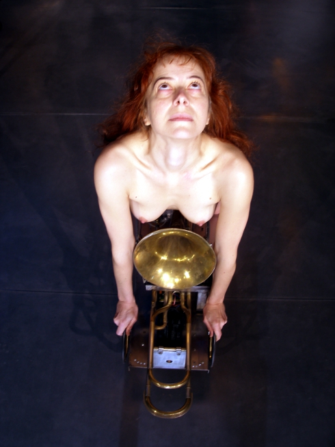
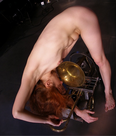
<Bono>
an automated rotary valve trombone
Godfried-Willem
RAES
2005-2010
|
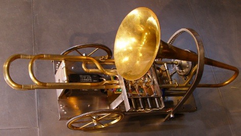
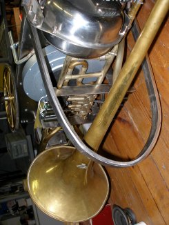
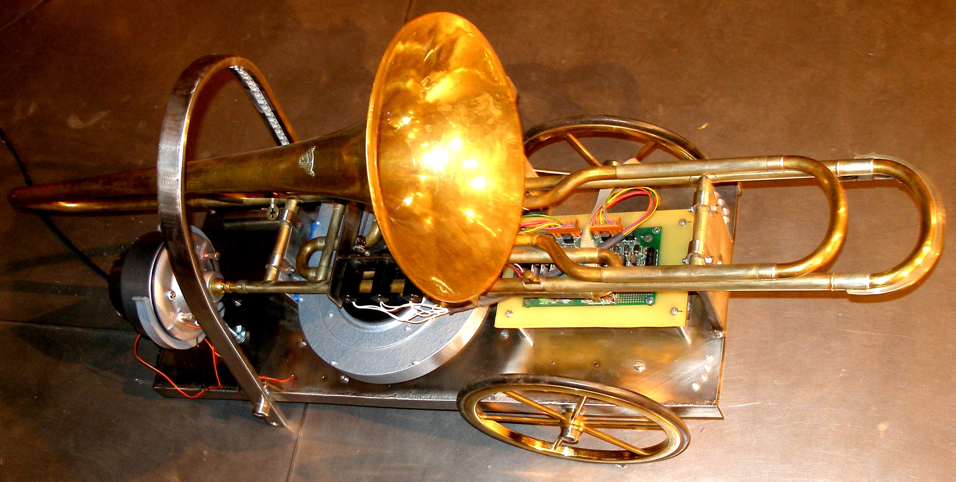
This musical robot consists of an old but extremely well made valve trombone,
found on the Ghent flea market. It was build by the famous brass instrument
builders V.F.Cerveny and Sons in Hradec Kralove (Tchechia) 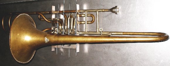 We
equipped it with an automated playing head and four automated valves. In the
first building phase the wind supply -we used a small rotating compressor- was
also automated, however, later we improved the design and could drop the wind
supply alltogether. Controlling this robot is realized using a standard midi
protocol. This instrument has four rotary valves. Normally these valves rotate
over a 90 degree angle under finger operation. The drawing illustrates the internal
workings of this type of valve:
We
equipped it with an automated playing head and four automated valves. In the
first building phase the wind supply -we used a small rotating compressor- was
also automated, however, later we improved the design and could drop the wind
supply alltogether. Controlling this robot is realized using a standard midi
protocol. This instrument has four rotary valves. Normally these valves rotate
over a 90 degree angle under finger operation. The drawing illustrates the internal
workings of this type of valve:  When
we started the automation of this mechanism we had many technical choices with
regard to the way the valves could be operated:
When
we started the automation of this mechanism we had many technical choices with
regard to the way the valves could be operated:
1. The most trivial solution seemed to be to preserve the existing mechanism
and replace the human fingers with push type solenoids pushing on the existing
fingerplates. The problem with this approach is that operation of the valves
is very sluggish, mainly because the return spring now also has to lift up the
anchor of the solenoid. A second problem is that due to the many mechanical
parts, the action tends to be rather noisy. For these reason we abandoned this
track.
2. A second possibility consists of activating the axis of the valves directly
using angular displacement solenoids. The problem here is that angular displacement
solenoids operating over full 90 degrees angles are difficult to find, 45 degrees
being the most common standard. Also, the 90 degree types are pretty noisy whenever
they reach their end positions. One could of course go with a design using two
45 degree rotary solenoids for each valve, each operating on another side of
the axis. At rest all valves would then be in a halfway depressed state. In
this case we would need eight solenoids.
3. A third possibility was to use motors (stepper or servo) to rotate the valves
on their axis in steps of 90 degrees. The advantage of this last approach being
the unsurpassed speed that can be achieved from the valves, however at the detriment
of complexity: position sensors become a mandatory requirement. With stepper
motors, small types doing 7.5 degrees per step could be used. These require
12 steps for a 90 degree angle and are pretty silent in operation. However their
torque is marginal if they have to rotate worn out or not to well greased valves.
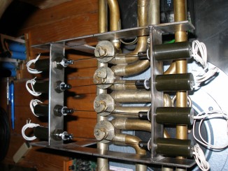
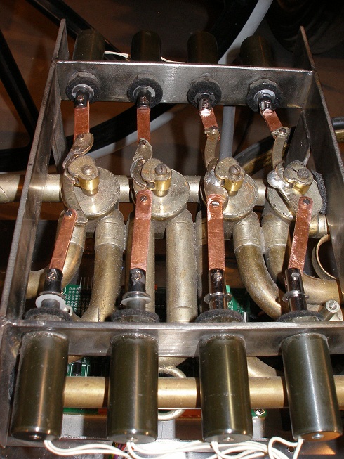
4. A fourth possibility consist of using eight pull-type tubular solenoids
working on the eccentric pivot point on the valve shafts. Here we get rid of
the entire original mechanism and replace it with traction wires made of 1.6
mm stainless steel rods.
During the research phase we tried out the third and the fourth possibility.
We rejected the third mainly because the acceleration of the steppers could
never be made fast enough for a good and lively response of the keys. The fourth
possibility was realized using Black Knight pull type solenoids. In order to
get fast response we drive them using our pulse/hold PIC controller boards as
developed for our <player piano> , for <Bako> and for <Qt>.
The force they are able to develop is only marginal for smooth operation in
this robot. The circuit principle is shown in the schematic below:
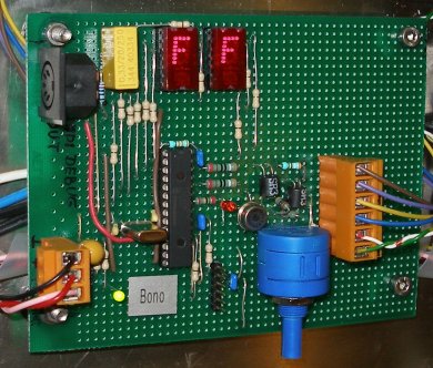
In total, three PIC-microcontroller boards are used in this robot: A first
one placed on the midi-input and hub board, controlling the motor functions,
the expression valve and the visual effects. A second one takes care of the
valve combinations used for resonance on the required notes. A third one, -equipped
with a dsPIC, type 30F3010, controlling the artificial mouth assembly and the
pitch generation. This board also has two digit decimal displays, showing the
midi note playing. We used a TIL311 display, because this type has an on chip
BCD to 7-segment decoder. When no note is playing, the display will read 'FF'.
(Not zero, because 0 is a valid midi note!).
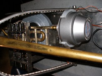
For the construction of the artificial mouth we could build further on the
experience gained when realizing our automated sousaphone, <So>. However,
we also tried out a few other sound generating mechanisms prior to taking up
the <So> design again. Thus we tried a servo motor driven rotary valve
working on compressed air. This worked soundwise excellently - we could obtain
really impressive fortissimos for instance over the entire compass. We finally
rejected the application of this technology because we were unable to control
the servo fast enough in going from the one speed to the other as required for
proper generation of musical pitches. The second problem had to with the difficulty
in finding really silent compressors.
The overview of the total circuitry looks like:
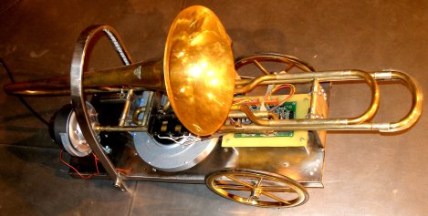
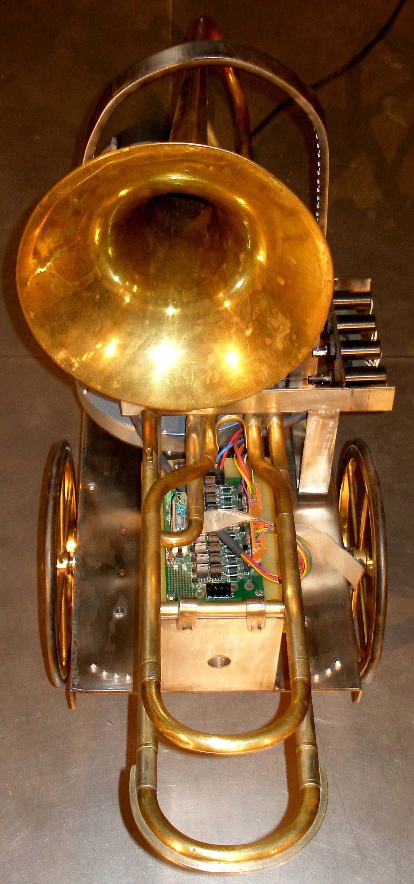
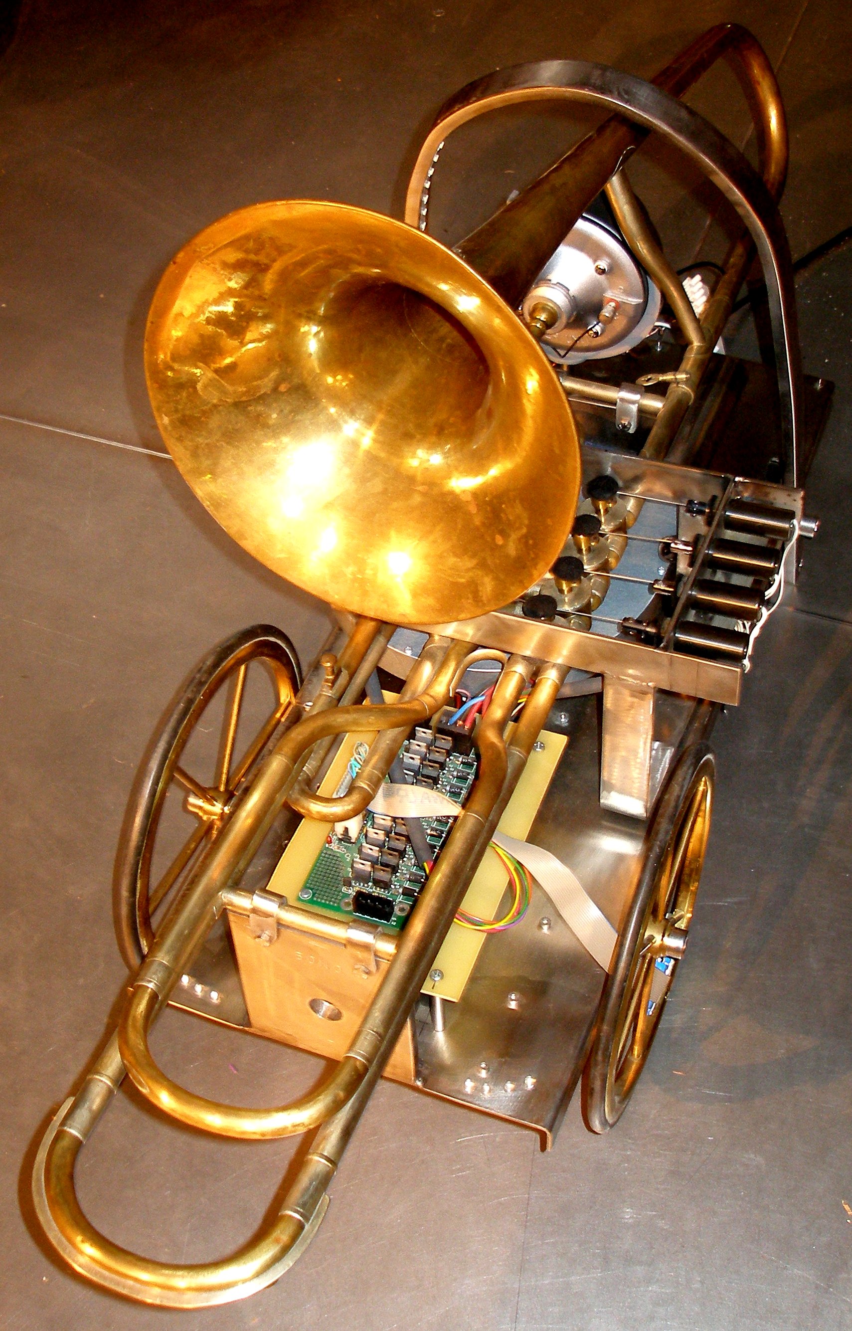
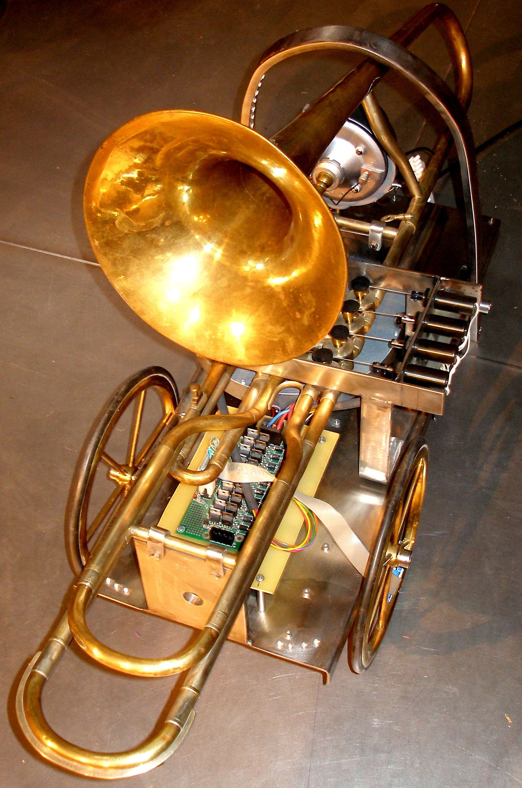
The <Bono> robot was designed to be suspended, thus reducing floor space
requirements for the Logos robot orchestra. All mechanical parts were made from
stainless steel, welded together using the manual TIG process. All serviceable
parts can be taken apart however.
Power supply voltages and currents:
- +12V/ 4A power supply for solenoids (hold voltage) - non stabilized (17.8V
max) Also used for lights.
- -24V/ 4A for solenoid pulses. (velo voltage, non stabilized).
- +28V/-28V dc power for amp. (toroidal transformer)
- +5V/ 500mA for processor boards
Midi Mapping and implementation:
Bono midi channel: 13 (counting from 0)
Midi note range: [0-33] 34 - 79 [80-96]. Note on with velocity is implemented
and has a wide control range. For a good attack, low values for velo and a high
setting for controller 17 should be used. (see further in this implementation
tabel).
Note Off commands are required, but can be dropped for pure legato playing.
Note-off starts the release of the mouthpiece driver and de-energizes the valve
solenoids.
Lights:
- Note 120 = Yellow LED cascade left
- Note 121 = Yellow LED cascade right
- Note 122 = Yellow LED's frontal left
- Note 123 = Yellow LED's frontal right
- Note 124 = nc
- Note 125 = Brigth white 3W LED spot
- Note 126 = pwm - nc
- Note 127 = pwm - nc
Controller 7: General volume control. There is a build in integrator, such
that very fast changes for this controller are averaged out. Integration time
is in the order of 15ms. This is the controller to use for crescendo and descrescendo
playing. It also can be used as an excellent tremolo/flatterzunge controller
as well as for advanced enveloppe control. Note that this controller also affects
the timbre of the produced sound. The most useable range is between 10 and 64.
Controller 17 is used for the attack level and thus contributes to the volume
scaling. Note that this setting affects greatly the effect of the velocity byte
as well as that off the attack-time controller (controller nr.18). The intrinsic
relation is shown in the graph below:
Controller 13 changes the valve combination used for playing any particular
note. Bit 0 steers the 1/2 tone valve, bit 1 the 1 tone valve, bit 2 the minor
thirth valve and bit 3 the fourth valve. This controller can be send whilst
a note is playing. Send it when no note is playing has no effect.
| Value |
-2 1/2t |
-1 1/2t |
-1t |
-1/2t |
| 0 |
off |
off |
off |
off |
| 1 |
off |
off |
off |
on |
| 2 |
off |
off |
on |
off |
| 3 |
off |
off |
on |
on |
| 4 |
off |
on |
off |
off |
| 5 |
off |
on |
off |
on |
| 6 |
off |
on |
on |
off |
| 7 |
off |
on |
on |
on |
| 8 |
on |
off |
off |
off |
| 9 |
on |
off |
off |
on |
| 10 |
on |
off |
on |
off |
| 11 |
on |
off |
on |
on |
| 12 |
on |
on |
off |
off |
| 13 |
on |
on |
off |
on |
| 14 |
on |
on |
on |
off |
| 15 |
on |
on |
on |
on |
| |
|
|
|
|
Controller 18: attack time (see graph under controller 17). This sets the time
the volume will remain at the level set by controller 17, before falling back
to the value set with the velocity byte.
Controller 19: release time for note-offs.(see graph under controller 17).
When legato playing is in use, meaning that you do not send note-offs but only
new note on's, there will be no release section in the enveloppe and thus the
use of this controller will become meaningless.
Controller 20: tuning (diapason, default is 440Hz). The range is limited to
maximum 50 cents (a quartertone) upwards.
Controller 25: Valve solenoid pulse duration (for research and development
only)
Controller 66: Machine power on/off switch (mandatory). As long as controller
66 is not set to on (any non-zero value), <Bono> will not play anything.
Reception of this controller does not change the program change in use.
Controller 123 switches all notes off. Releases the solenoid valves. Resets
the controllers, except nr.20. Also switches off the lights. It does not change
the program change command in use.
Program change: implemented. Program changes are used to select different lookup
tables for the fingering of the notes. By default, program 0 is selected with
the default lookup table. So after a cold boot, program change 0 will always
be in use.
| Value |
remarks |
| 0 |
default acoustic theory [detailed mapping]
(txt.file) |
| 1 |
empirical
[detailed mapping] |
| 2 |
user table 1 [just intonation - to be done] |
| 3 |
user table 2 [quartertone mapping - to be done] |
| other |
invalid |
Pitch bend implemented. The range is limited to a semitone, thus a quartertone
up or down. Pitch bend can be used for microtonal music as well as for vibrato
control. The coding follows from the example below, given for a fragment of
a quartertone scale:
 Most good sequencer
software (such as Cakewalk or Sonar) use the signed 14 bit format. Note that
one unit of the msb corresponds exactly to a 0.78 cent interval. To convert
fractional midi to the msb only pitchbend to apply follow following procedure:
if the fractional part is <= 0.5 then msb= 63 + (FRAC(note) * 128), if the
fractional part is larger than 0.5, we should switch on the note + 1 and lower
the pitch with msb= (1-FRAC(note)) * 128.
Most good sequencer
software (such as Cakewalk or Sonar) use the signed 14 bit format. Note that
one unit of the msb corresponds exactly to a 0.78 cent interval. To convert
fractional midi to the msb only pitchbend to apply follow following procedure:
if the fractional part is <= 0.5 then msb= 63 + (FRAC(note) * 128), if the
fractional part is larger than 0.5, we should switch on the note + 1 and lower
the pitch with msb= (1-FRAC(note)) * 128.
Technical specifications:
- size: height: 450mm, length: 1050mm, depth: 350mm. Flightcase size: 980
x 360 x 500.
- weight: to be determined (estimate: 30kg)
- transportation: <Bono> should only be transported in its special flightcase.
Weight with flightcase:
- power: 230V ac / 100W
- Tuning: based on A = 440 Hz (within 1%). The tuning can be adjusted.
- Ambitus: [0- 21] 22 - 78 [79-94]
- Insurance value: 9.500 Euro
Design and construction: dr.Godfried-Willem
Raes
Collaborators on the construction of this robot:
- Kristof Lauwers (GMT implementation)
- Xavier Verhelst (research)
- Johannes Taelman (PIC coding)
Music composed for <Bono>:
- Godfried-Willem Raes "Calls for Bono"
- Godfried-Willem Raes "Just Calls for Brass" (with <Korn>,
<Heli> and <So>)
Nederlands:
Robot: <Bono>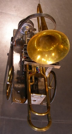
In het Logos robot orkest hadden we behoefte aan wat meer variatie
in de lage blaasinstrumenten, in dit tessituurgebied domineerden immers alleen
<So> en de toch wat minder responsieve <Bako>.
Voor deze automatische ventieltrombone gebruikten we bij onze eerste experimenten
-waarbij we zochten naar een alternatief voor het mechanisme dat we ontwikkelden
voor <So>- een persluchtmotor met drie schoepen als klankopwekkingsmechanisme.
Deze persluchtmotor -hier gebruikt als kompressor - werd daarbij aangedreven
door een uiterst nauwkeurige servo motor. De korrektheid van de intonatie staat
of valt immers met de precizie van deze motor en zijn aansturing. Zouden we
een dergelijk systeem zonder meer toepassen, dan zou de luidheid van de voortgebrachte
tonen een funktie zijn van de toonhoogte. Dit is muzikaal uiteraard niet erg
wenselijk. Daarom is ook een regeling van de windinlaat van de kompressor hier
een absolute vereiste. Het mechanisme werkte naar toonkwaliteit erg goed en
was in staat impressionante fortissimos te genereren, maar leed aan een niet
te vermijden traagheid bij het snel wisselen van tonen. Een na enige tijd onuitstaanbaar
portamento bleef een inherente eigenschap van het koncept. Daarom pasten we
in de tweede versie opnieuw een moving coil driver toe, een in een aantal opzichten
verbeterde versie van die toegepast in <So>. De rezultaten in de hoogte
van de tessituur bleven echter onbevredigend, zodat we in versie drie -de meest
recente- overstapten naar het gebruik van een akoestische impedantietransformator
gekoppeld aan een 100W kompressiedriver. Hierdoor werd het oorspronkelijk ontwikkelde
windmechanisme overbodig. Van meet af aan bouwden we <Bono> zo, dat het
instrument ook probleemloos overweg kan met kwarttoonsmuziek en muziek in andere
stemmingen in het algemeen.
De ventielen op deze bijzonder goed gebouwde trombone zijn draaiventielen.
De Boheemse oorsprong van het instrument, gebouwd door V.F.Cerveny in Hradec
Kralove in het huidige Tchechie, is daar uiteraard niet vreemd aan. Daardoor
kon echter niet hetzelfde mechanisme worden toegepasten als bij <So>,
die met drie duwventielen is uitgerust. Deze ventielen moeten immers over een
hoek van 90 graden verdraaid worden om het ventiel te schakelen. In de ontwerpfaze
onderzochten we grondig de verschillende mogelijkheden:
1.- Toepassing van duwmagneten op de bestaande hefbomen voor de
vingers. Deze triviale mogelijkheid dienden we te verwerpen vanwege de te grote
traagheid: de terugslagveren moeten nu immers ook het gewicht van de magneetkern
omhoogduwen. Bovendien leidde de overmaat aan hefboompjes en draaipunten tot
veel bijgeluiden, wrijvingsverliezen, traagheid en onbetrouwbaarheid.
2.- Toepassing van draai-elektromagneten. Deze hebben echter standaard
een hoekverdraaiing beperkt tot 45 graden. Negentig graden types zijn zeldzaam
en extreem duur. Bovendien zijn ze lawaaierig bij het bereiken van hun eindpositie.
3.- Toepassing van stappenmotoren. Hiermee kunnen de ventielen
telkens over een hoek van 90 graden worden verdraaid. Maar, door torsie en wrijving
bestaan de mogelijkheid dat de motoren op gezette tijden een of meer stappen
missen waardoor de afregeling verloren gaat. Om dit te kompenseren zijn dan
weer positiebepalingssensoren nodig. We hebben een proefprojektje opgezet met
stappenmotoren met een stapgrootte van 7.5 graden, maar de versnellings mogelijkheden
van deze motoren bleek te klein om erg soepel met de ventielen te kunnen omgaan.
4.- Toepassing van dubbele trek of duw magneten aangrijpend in
het excenter punt van de oorspronkelijke ventielen, waarbij dan het gehele originele
hefboommechanisme wordt verwijderd. Hiervoor pasten we Black Knight trekmagneten
toe, voorzien van uit inox staaf geplooide trakturen. om die te plooien ontwikkelden
we een speciale plooimal. De trakturen dienen immers onderling identisch te
zijn. De lineaire verplaatsing wordt nu 10mm voor een draaihoek van 45 graden.
Deze robot maakt voor zijn interne besturing gebruik van drie
mikroprocessoren: twee 18F2525 PIC's en een 30F3010 dsPIC. Gedetailleerde schakelschemas
zijn aan het einde van deze pagina toegevoegd. Om het nodige podiumoppervlak
voor het <M&M> robotorkest niet nog verder te vergroten, besloten
we deze automaat te bouwen voor ophanging, hoewel opstelling op de bodem ook
mogelijk is.
Godfried-Willem Raes
Pictures taken during the building of the <Bono>
robot:


Construction Diary:
- 15.10.2005: first ideas and practical sketches.
- 16.10.2005: experiments with sound production mechanism.
- 18.12.2005: discussion on PIC implementation possibilities with Johannes
Taelman.
- 17.01.2006: calculations for a design using a Dunker servo motor (70-4000rpm)
coupled to a rotary compressor and a valve controlled wind-inlet mechanism.
- 19.01.2006: experimental disassembly of a dentists compressor in order to
check its suitability as sound producing device in a bass brass instrument.
Brand name: Fricar A.G., Zuerich.
- 20.01.2006: The air does not pulse enough at the output. The device seems
to be optimized for suction rather than compression. Oddly enough, but blowing
or sucking does not make a serious difference if it comes to sound production
and projection. The sound stems mostly from the resonance in the instrument
and not from the windflow.
- 22.01.2006: Search for axis coupling of horn-compressor to servo motor.
- 20.03.2006: trombone back from repair and tuning in instrument building
workshop Bernard d'Harte.
- 23.03.2006: calculation and measurement of required activation forces for
the valves. The valves require a force of 15N to become completely depressed.
Thus the normal Lucas-Ledex STA type, diameter 26mm, (7.8N @ 100%, 5mm travel)
cannot be used without overdrive! The Laukhuff types (blue double coils on
24V) specify 10N as maximum force.
- 31.07.2006: experiments with stepping motors on <Qt> in order to find
out their useability as valve drivers in <Bono>. They were evaluated
as too noisy for application in musical instruments including a 'soft' dynamic
range.
- 18.12.2006: experiments with ball-head valves as sound generators. The sound
is nice and can attain extremely high pressure levels, but we fear extreme
wear very fast on the ball-head valve...
- 27.07.2007: building further on the experience gained with the renovation
of the <So> robot circuitry, we developed a new board for the mouthpiece
driver, using a microchip dsPIC microcontroller.
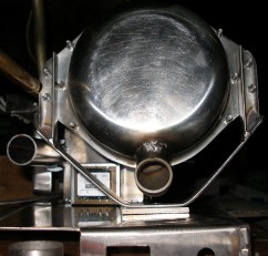
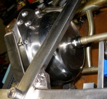
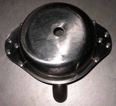
- 30.07.2007: TIG welding works on the artificial mouth assembly. This was
an extremely difficult job, since the stainless steel pots used to form the
container are less then 0.5mm thick. Wind inlet 30mm stainless steel tube,
through hole for electrical wire (4mm) , mouthpiece holder with clamping and
adjustment mechanism.
- 31.07.2007: Research work on automation of the rotary valves: stepper motors
or pull type solenoids. Frame welded for eigth Black Knight tubular solenoids.
(Frame size: 250 x 150 x 30, material thickness 3mm)
- 01.08.2007: First design of support structure: base plate 300 x 600mm, stainless
steel plate 3mm thick. Vertical support pieces for the trombone: 100 x 10
x 120, to be welded on base plate. The pieces have 5mm drilled holes for mounting
the trombone witch clamps. The solenoid assembly should be removable for maintenance
and adjustment. Mounting the robot on large wheels (such as used for <Bako>)
is an option.
- 02.08.2007: Bottom plate cut out and bend. Base plate size: 700 x 260. Thickness
2mm, AISI 316. TIG welding works on bottom plate. We decided to suspend the
robot upside down (so, the bottom mounting plate, will become the 'ceiling'
plate from which the instrument should be hung.) Mains power entry (3-prong
euroconnector) sawn out and switch hole drilled. Support and carrying plates
for trombone welded on chassis plate. If anyone follows us on this track:
dont use 2mm plate! Its an invitation to warping problems in the welding process.
We went for 2mm plate only to save some weigth, considering the robot was
to be suspended. 3mm stainless steel works really a lot easier!
- 03.08.2007: Compressor mounting components welded on chassis plate. Reinforcing
ribs cut out. Design of adjustable valve solenoid holder on chassis plate.
- 05.08.2007: Mouth assembly holder constructed. It mounts on the base plate
with an M12 bolt and nut. Spacers should be used for precize vertical adjustment
of the mouthpiece. Bending former constructed for the making of the tractures
for the valves. Valve solenoid holder, part 1, welded.
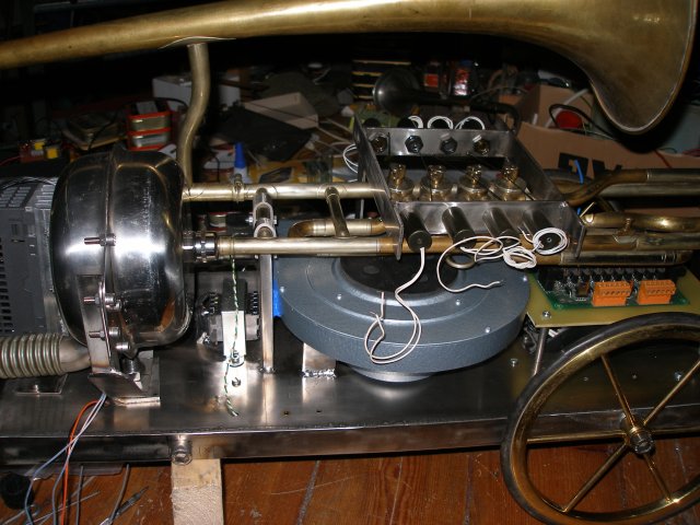
- 06.08.2007: First tentative placement of artificial mouth assembly.
Air inlet to the mouth and air outlet from the compressor can be seen on the
picture. Drilling of all mounting holes for the electronic circuitry. Drilling
of 12mm holes on the sides for either large wheels or suspension hooks. Moving
coil driver prepared and mounted in the mouth cavity container. Research on
pad material for the lip subtitute. Saxophone leather pads might be to soft
for a good sound in the trebble.
- 07.08.2007: diverse prototypes gemaakt van moving coil drivers voor koperblaasembouchures.
Diverse materialen: neopreen, styrofoam, latex, siliconenrubber, acetaat.
Om 18u alle werk stilgelegd wegens chirurgische ingreep op linkerwijsvinger.
Het bono werk wordt voor minstens een week stilgelegd. [due to a surgical
treatment of my left index finger, I cannot do any mechanical kind of job
for at least a week or so].
- 08.08.2007: Metal cable glands ordered from Farnell. These are for adjustable
mounting of the mouthpiece on the moving coil assembly.
- 09.08.2007: Moving coil driver audio amp ordered from Farnell: ILP's HY2001
type should be more then powerfull enough. Power transformer required: 20-0-20V
ac - 30Watt. This is similar than the HY30 type used in <So>.
- 10.08.2007: Extensive tests with expanded neoprene as lip material. These
tests seem to lead to an entire world of applications of speakers as precision
analogue valve drivers for low air pressure.
- 14.08.2007: Playing head reassembled and tested with sound generator. Power
amp build up with toroidal transformer 2x18V.
- 15.08.2007: Mounting holes drilled for PC boards and power supplies. Old
brass wheels found, for horizontal mounting of the robot. Construction chassis
components for mounting of Siemens Sinamics motor controller.
- 16.08.2007: rewiring of Laukhuff motor for 3-phase operation. Test session
with moving coil driver: as for now, it seems very difficult to get it to
speak notes higher than 64. In order to be compatible with normal trombone
writing, we should extend this to at least note 74. At 7V rms drive, the coil
gets pretty hot, so it seems essential to apply wind, even alone for cooling.
As usual, loudspeaker spec sheets from manufacturers appear to be completely
unreliable.
- 17.08.2007: Wheel spindles in brass drilled out. M12 thread welded to chassis.
More mounting holes drilled in chassis for placement of electronic components
and circuitry. Yellow LED spotlites purchased.
- 18.08.2007: Mounting and wiring of power supply related components on chassis.
Adjustment of mounting hole for moving coil assembly. Motor compressor mounted,
One single M8 bolt and blue loctite silicon kit. Siemens Sinamics motor controller
mounted.
- 19.08.2007: Test assembly of all parts.
- 20.08.2007: Electric tests of power supplies. Tone generator tests.
- 21.08.2007: Design prototype board for the dsPIC circuit with display. We
use TIL311 types, because they have an integrated BCD to 7-segment decoder.
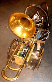
- 25.08.2007: Rough assembly of components:
 It looks like we will need to design some kind of protective structure around
the backside of the robot, such that it can be placed on a surface without
risk of damaging essential components.
It looks like we will need to design some kind of protective structure around
the backside of the robot, such that it can be placed on a surface without
risk of damaging essential components.
- 27.08.2007: Spec sheet for the the PIC firmware, version 1.0.
- 30.08.2007: Bono ds-pic board passed to Johannes Taelman for code development.
- 23.11.2007: Support for suspension and protection bend in 10mm thick stainless
steel (25mm wide). This part can be taken off by loosening the M12 inbus bolts.
- 24.11.2007: Welding finished on support. Mounting under a 75° degree
angle (60+15). For attaching suspension hooks, we drilled two 10mm holes in
the end points. Midi-hub and motor control board mounted and wired,
- 25.11.2007: Bright yellow LED lights through base panel mounted and wired.
Motor controller programmed. (Siemens Sinamics, same settings as used in <So>)
. Power supply voltages checked. Hub board powered up. There is a noticable
mechanical hum from the transformers. Maybe we should damp it either by mounting
them with silicone compound or immersion in epoxy resin.
- 27.11.2007: Mounting valve control board.
 This
is the same board as we have used for our <Harma> robot (Board version
1.0). Wiring finalized. Connector X3 steers the pull-off solenoids, connector
X4 the pull-on solenoids. Wire color coding is: red=positive power supply
voltage, orange= left solenoid/valve, yellow= second left, green= second right,
purple= right solenoid/valve. Two outputs remain as yet unused.
This
is the same board as we have used for our <Harma> robot (Board version
1.0). Wiring finalized. Connector X3 steers the pull-off solenoids, connector
X4 the pull-on solenoids. Wire color coding is: red=positive power supply
voltage, orange= left solenoid/valve, yellow= second left, green= second right,
purple= right solenoid/valve. Two outputs remain as yet unused.
- 28.11.2007: Construction of the solenoid connecting rods reconsidered. M2x20
stainless steel bolts ordered.
- 29.11.2007: New connecting rods bend from stainless steel wire.
- 30.11.2007: Working session on PIC firmware. PIC1, midihub board programmed.
This PIC has lookups for wind-pressure in function of note (pitch) comparable
to what we implemented for <So>.

- 01.12.2007: On pulse/hold board output X3/4 disabled by cutting out the
connection to the mosfet base and the PNP transistor. This was required in
order to use the in circuit debugger with this board. So, now the fourth off-solenoid
is connected to X3-5. Output X4-10 is now the only unused and available output.
PIC2 programmed with a first code version by Johannes Taelman. Velo implemented
but now kept at a constant value of 20ms.
- 02.12.2007: Mechanical work on the solenoid driven rotary valves finalised.
DS-PIC board finalised with the VCA circuitry and transformer coupling.
 The audio transformer used is a pre-world war two type taken from old professional
audio equipment with vacuum tubes. It measured out perfectly o.k. for our
application here.
The audio transformer used is a pre-world war two type taken from old professional
audio equipment with vacuum tubes. It measured out perfectly o.k. for our
application here.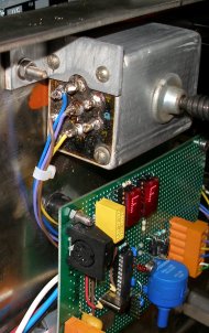 It's very well screened and shows up a very lineair frequency response. There
is no type number nor marks other than ROLO 295 on the part. The reason a
transformer is used is mainly as a filter to block of the high frequency components
in the PWM signal. DC-restoration and blocking was a secondary bonus.
It's very well screened and shows up a very lineair frequency response. There
is no type number nor marks other than ROLO 295 on the part. The reason a
transformer is used is mainly as a filter to block of the high frequency components
in the PWM signal. DC-restoration and blocking was a secondary bonus.
- 04.12.2007: Transformer mounting finalized. Solenoid anchors fixed to tracture
wires with stainless steel M2 bolts and nuts.
- 07.12.2007: Programming session with Johannes Taelman on the DS-PIC. Some
hardware bugs and DS-PIC pin incompatibilities solved. Bono can play its first
notes...
- 08.12.2007: DS-PIC board not responding when motor is activated.... This
sounds like induction from motor PWM into sensitive input of the PIC preventing
it to operate properly... With the motor disabled, the DS pic does work. Controllers
7 and 66 work fine, controllers 17 and 18 need different scaling factors.
Controller 66 does not seem to work at all on PIC1 (no activity at all on
PIC pin 16. Stuck on zero... Nothing wrong with the hardware here). Moving
coil driver burned out... (probably because we let it work with the motor
disabled. The wind does in fact cool the voice coil in the driver!). Old driver
was an ITT model rated for 20W rms. All M2 nuts on the solenoid valves secured
with crazy glue (cyanacrylate).
- 09.12.2007: Mouth driver completely rebuild. Now with a more powerfull Aciko
bass driver rated 50W. We have to wait at least 24h now for the silicon compound
to cure. Mouthpiece reshaped on the lathe to allow for a somewhat larger regulating
traject. Controller 66 not working was a bug in the PIC1 code. It used X17-3
instead of X11-2. By soldering an IRL640 mosfet in at the appropriate spot
on the midihub board this was solved. The tuning controller (nr.20) should
be set to 5 for a tuning to 440Hz within 1 cent. The range is a quartertone
upwards (for ctrl 20 = 127). Test code in GMT rewritten. Controller 14 is
not working... maybe ctrl 25 was implemented instead... None are working.
When we revize the PIC2 firmware, we should implement this as controller 25,
since that will make compatibility with music written for <So> better.
Another bug now in the PIC2 code, is that the valve solenoids do not hold
for the duration of the requested note.
- 10.12.2007: New test session after silicone compound curing. Sound production
works fine in the note range 10-32. Between 33 and 48 the mouthpiece adjustment
becomes very critical and at some positions, it octaves an octave down, so
it functions as a mechanical frequency divider. Wind pressure should be adjusted
as high as possible. Pitch bend seems already implemented but does not work
symmetrical around the 64 value for the msb. The tremolo test using the optor
works absolutely fine. It's response is actually better than what we hoped
to get from the design. It seems that a controller for the DC offset of the
wave form (wave symmetry control) would be very welcome. We came to the same
conclusion in the design of <So>.
- 13.12.2007: Further work on the allignment of the playing head.
- 20.12.2007: New head submitted to new tests after mounting and regulating.
Sound demo given to Sebastian Bradt.
- 21.12.2007: Bono seems to play an octave higher than what the midi note
command says. This should be remedied in the DS pic code. For the higher notes
(from note 60 -real pitch- on, a waveform assymmetry or a positive DC offset
is really required. For the extreme low, a negative DC offset seems required.
- 22.12.2007: Continued research on the sound mechanism. Although the pitch
generator is not in error, we will have to map all notes an octave higher,
since the mechanical construction of the mouthpiece causes the sound to play
an octave higher. Now we adjusted the mouthpiece such as to render the best
possible range for the mid-low notes on the trombone.
- 24.12.2007: Bono speelt zijn eerste echte muzikale kompositie...
- 25.12.2007: Wegwerken mechanische resonanties van de metalen onderdelen
en schoefverbindingen.
- 26.12.2007: Aanmaak testfiles voor Bono. Praktijktests met tremolo en vibrato
mogelijkheden.
- 28.12.2007: Werksessie PIC programmering met Johannes Taelman. Op PIC2 is
nu controller 25 geimplementeerd voor de sturing van de pulsduur op de ventielen.
- 03.01.2008: Uitwerking GMT player implementatie voor Bono.
- 05.01.2008: Further hardware tests.
- 08.01.2008: Golfvorm-assymetrie blijkt essentieel voor een goede toonvorming.
- 11.01.2008: ds-PIC crashes zijn persistent... Konstruktie tussenplaat onder
het ds-PIC board.
- 16.01.2008: Bono speelt voor het eerst mee in het M&M orkest...
- 30.05.2008: Twee LED-strips (geel) toegevoegd aan de binnenzijde van de
hangbeugel.
- 27.07.2008: Mondholte van Bono opnieuw geopend. Ontevreden met de klank.
Deze keer kleefden we een precizie-geslepen stalen legring op de kunststof
lipplaat. De pot werd nu met blauwe Loctite gasking silicone zorgvuldig luchtdicht
gemaakt.
- 28.07.2008: De klank blijft onbevredigend, al is de extreme laagte (noten
12 tot 26) nu wel goed. De aansturing met zuivere blokgolven klinkt in elk
geval beter dan de modified-sine wave die nu wordt gegenereerd (ds-PIC board)
. Controller 25 blijkt niet te werken. De lookups voor de vingerzettingen
werken ook nog niet (pulse-hold board).
- 29.07.2008: Hele dag expimenten uitgevoerd met diverse alternatieve opbouwwijzen
voor de mondstukdriver.
- 30.07.2008: Ontwerp en konstruktie van een nieuwe mondholtepot. Rezultaat:
de noten 12 tot en met 32 klinken goed nu, maar de klinkende noten zijn een
oktaaf hoger. Controller settings nu: ctrl 7: 127 (mag varieren), ctrl 17:
127, ctrl 18: 120 (variatie mogelijk tussen 110-127), ctrl 66: 127 (ON), ctrl
1: ca.50 (wind). Bruikbare waarde voor de velocities zijn nu 48 tot 127. De
dynamiek is evenwel nog steeds te klein.
- 29.08.2008: Aansluiting van de gele ledjes krans in de ophangboog. (12V)
- 12.10.2008: Herbeschouwing van het mondstukstuurmechanisme. Het huidige
mechanisme werkt maar haalt niet het verwachte geluidsvolume. Wellicht kunnen
we hier voordeel halen uit de research verricht rond robots zoals <Ob>
en de op stapel staande <Heli>.
- 30.10.2008: Trombonemondstuk afgedraaid op de draaibank voor test met een
kompressiedriver zoals gebouwd voor <Korn>, <Heli> en <Ob>.
De uitsturing is nu echter te klein. De amplitude neemt toe met de toonhoogte,
wat hier niet wenselijk is. Wellicht zit er ook een bug in het schakelschema
rond de uitgangstransfo en moet die primair wel degelijk een middenaftakking
hebben, te verbinden met hetzij massa hetzij +5V. Om dit te onderzoeken vervingen
we de transfo door een nieuwe 1:1 audio transfo met middenaftakking (600 Ohm
impedantie, Farnell 117-2421). De 390 Ohm belastingsweerstand na de optors
moest nu worden weggeknipt. Het al of niet met massa verbinden van de middenaftakking
blijkt absoluut geen verschil uit te maken. Met deze wijzigingen is de klank
in elk geval al heel wat beter. Resterende fouten: er moet een ruiskomponent
in het signaal worden toegevoegd, de tokken bij het in- en uitschakelen van
de noten moeten worden weggewerkt en de oktaveringsfout moet verbeterd worden.
Nu speelt Bono alle noten een oktaaf hoger dan wat uitgestuurd wordt via midi.
Een gewenst neveneffekt is dat de audiotransfo nu ruim in verzadiging kan
worden gestuurd wat tot een gewenst cuivre effekt aanleiding kan geven.
- 31.10.2008: Ook de midihub PIC heeft nog een tekort: een van beide gele
kransLED's op de beugel is niet geimplementeerd. Er zit ook nog een bug in
de dsPIC firmware of in de GMT testkode: de amplitude controller werkt omgekeerd...
Om een of andere duistere reden durft de dsPIC ook wel vastlopen. Na ontvangst
van controller 66 blijkt hij het echter steevast opnieuw te doen.
- 01.11.2008: Hele werkdag rond de toonvorming in Bono. Het rezultaat is nu
redelijk goed, al is de klank eerder die van een trombone uit de oude muziek
dan wel die van het symfonisch orkest. De motor kan nu eigenlijk geelimineerd
worden, of gebruikt voor een speciaal effekt... We zitten wel nog met een
hinderlijke brom. Wellicht afkomstig van de 5V voeding. Uit te zoeken met
de skoop.
- 02.11.2008: Brom weggewerkt door toevoeging van twee 4.7mF elkos na de gelijkrichter
op het midihub board. GMT test kode aangepast aan de nieuwe specifikaties.
- 05.11.2008: Bono speelt zijn eerste partijen in het oude muziekrepertoire
met Marcel Ketels, Dirk Moelants en Stefaan Smagghe...
- 06.11.2008: Zoektocht naar een geschikte montagebeugel voor de motor driver.
Uiteindelijk zelf beugel, omtrek 384mm, vervaardigd uit inox met opgelaste
M12 x 80 bout. Traktuur van het vierde ventiel hersteld. Alle nu overbodig
geworden draden en konnektoren verwijderd.
- 07.11.2008: Konstruktie van een beschermplaat in glashelder 8mm dik polykarbonaat
voor de bovenzijde ter bescherming van de schakelingen bij ophanging. Afmetingen:
260 x 700mm. Voor het programmeren van de beide PIC processors (midi-hub en
dsPIC) moet deze plaat weggenomen worden.
- 11.11.2008: Herziening kode voor de dsPIC met Johannes Taelman. Transpositiefout
hersteld, klikken bij in en uitschakelen van noten weggewerkt, tessituur uitgebreid.
Kontroller 19 geimplementeerd voor de release snelheid. Midi implementatie
tabel aangepast. Door de uitbreiding van de tessituur hebben we nu echter
een nieuwe bug geintroduceerd: de lampjes zijn nu in het mogelijke tessituurbereik
terecht gekomen en dus niet meer zonder veel lawaai te gebruiken... Ook de
valve-lookups kloppen nu niet meer met de gegenereerde noten.
- 12.11.2008: GMT testkode aangepast en dokumentatie bijgewerkt. Een tijdelijke
bug fix voor de lampjes (alleen bruikbaar wanneer Bono geen noten te spelen
heeft...) bestaat erin controller 17 op 0 te zetten en dan de lampjes aan
te sturen. Bij de volgende herziening gaan we de lampjes in het bereik 120-127
leggen.
- 18.11.2008: <Bono> speelt zijn eerste officiele partijen als lid van
het M&M orkest.
- 18.12.2008: <Bono> has an important part in my just intonation composition
"Just Calls for Brass".
- 21.12.2008: Traktuur 2e ventiel bleek afgebroken. Nieuwe traktuur geplooid
uit 1.6mm inox lasstaaf. Traktuur wat kleiner gemaakt zodat de werking minder
bijgeluiden heeft.
- 25.01.2009: Kompressor-driver grondig uitgemeten. De impedantie daarvan
blijkt immers in hoge mate afhankelijk van de frekwentie zowel als van de
akoestische belasting. De belasting met een kapilair blijkt de impedantie
te doen toenemen.
- 26.01.2009: to do: remap lites 84 - 88 into 123 - 127. Add valve lookup's
and sysex. Add ctrl 13.
- 06.10.2009: Failure of motor compressor driver, due to heavy overload with
very low frequencies. Driver replaced.
- 22.06.2010: One of the tractures connecting the valves to the action solenoids
broke off. We replaced it, experimentaly, with a piece made in nylon and two
separate tracture rods. This construction -if it lasts long enough- might
perform better in terms of noisyness. Bono is ready again to join the orchestra
in the ancient music concert at Alden Biesen now.
- 11.08.2010: Start removal of the rotary compressor as it is no longer in
use on Bono.
- 12.08.2010: Motor completely removed. We can now replace the valve control
board to a more accessible place on the chassis.
- 20.09.2010: Start writing of new firmware for the hub controller and the
lites on Bono. Version 1.0, using the Proton+ compiler. Tested o.k. The lites
are bugfree now and there is even place for expansion. Source code added to
the Bono directory on the website.
- 21.09.2010: Firmware for the valve PIC controller rewritten and tested.
This is Version 2.0, since version 1.0 was written by Johannes Taelman.
- 22.09.2010: Remounting of the valve control board. Fingering controller
and program change implemented for the valve-board PIC controller.
- 23.09.2010: Valve firmware deep debug. New version flashed. Controller 13
fully implemented. Program change can be used to select different valve lookup
tables.
- 24.09.2010: Tractures for the fouth valve remade: now using a construction
with no less than five pivoting points. The aim is to get a more responsive
and above all, more silent mechanism.
- 25.09.2010: The new tracture for the fourth valve performs a lot more silent
than the others. However, the construction is now slightly too heavy.
- 26.09.2010: Valve PIC reprogrammed with firmware version 2.2. Start construction
of more tractures for the valves.
- 27.09.2010: All tractures remade and refitted. Testing required.
- 28.09.2010: Tracture for valve 3 resoldered, as it had a tendency of getting
stuck at times. Kristof working on optimal lookup tables for the valve combinations
to use with each possible note. These will be placed in the PIC firmware,
selectable with program change commands. Deficiency discovered in the Microchip
PicKit2 programmer: its 'verification' is not trustworthy, as it even reports
verify o.k. when the programmer is not connected to the programming inputs
of the PIC to be programmed... Could also be a bug in the Proton+ compiler.
- 29.09.2010: Further work on lookups. Demonstration for Jonas Jurkunas.
- 01.10.2010: Empirical lookup table for the valve combinations finished and
flashed. This lookup table will be used on reception of program change 1.
At start up the lookup table used will be program change 0, or the table derived
from acoustical theory.
- 14.10.2010: New pictures taken from the new bono...
- 10.08.2011: Strange noises originating from the valve caps resonating on
notes 63 to 70. Cured with a layer of Loctite 5920 silicone between the sliding
caps on the valves. Valve caps tightened a bit.
- 21.08.2011: Further examination of the mechanical resonances that still
occur on some notes.
- 18.11.2011: Glissando playing now fully implemented under GMT. Used in 'Slones',
a piece for robotic wind instruments and a live trombone player.
- 09.03.2013: Start design for a flight case, as Bono has to join the orchestra
in Glasgow...
- 11.03.2013: TIG welding works on the skeleton for the flight case for <Bono>.
- 12.03.2013: Welding works on the flightcase finished. Bottom plate in MDM
sawn and glued in place.
- 13.03.2013: Further work on the flightcase: mounting of side panels, handles
and hinges.
- 14.03.2013: Flightcase for <Bono> finished.
17.03.2013: Pictures made to document the way <Bono> fits in its flightcase: Note that the horn has to be taken of beforehand!
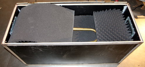 .
Wrap the horn in foam... and close the case:
.
Wrap the horn in foam... and close the case:  The case should never be turned on the sides nor upside down.
- 20.04.2013: <Bono> survived the trip to Glasgow very well! We expect
him back in Ghent on monday 22nd of april.
- 23.04.2013: Bono perfectly healty on return from Glasgow. The flightcase
works fine.
- 02.10.2013: Portuguese composer Jonas Runa at work with <Bono> during
his stay at Artist-in-residence at Logos. Preparing his pieces to be performed
at the Venice Biennale, october 12th.
- 09.10.2013: <Bono> left this morning for its appearance on the Venice
Biennale on october 12th...
- 28.10.2016: <Bono> on the road to Brugge for 'Iedereen Klassiek'
- 30.10.2016: Returned safely from Bruges.
- 22.06.2018: Compressor driver found blown out. After replacement with a
new Padu driver, everything was working again. We should limit the note range
on the dsPic to prevent this to happen again.
- 13.07.2018: <Bono> played the opening of the Ghent Feasts at Sint
Jacobs.
- 29.07.2019: <Bono> returned from 6-days of playing at Tomorrowland.
Some cleanup required now. Horn repolished. Checked o.k.
- 14.09.2023 - 02.10.2023: <Bono> participated in the Zeroth Law production
in the Deutsche Oper Berlin.
- 02.10.2023: <Bono> returned safely and in good shape from Berlin.
Only some of the solenoid anchors had to be reseated.
To be done on <Bono>:
- limit note range on dsPIC. The very low notes are potentially dangerous
for the hardware (motor driver).
- add noise in the dsPIC firmware, controllable with midi ctrl. 1.
- the 470 Ohms resistors in series with the LED section of the Silonex optors
should be replaced with much larger value resistors in order to improve the
useable range for controller 7. This was checked out on <Fa>, april
2011.
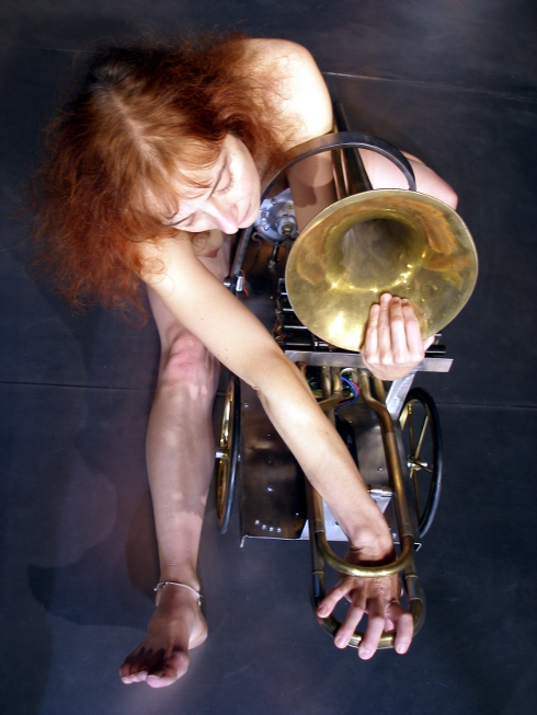
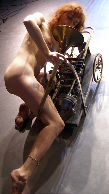
Robody Bono Pictures:
Last update: 2025-08-29
by Godfried-Willem Raes
Technical drawings and data
sheets:
Midi input board and PIC controller:
Midi buffers and thru ports:
Microprocessor section (motor control & lights):


Solenoids used for the valve mechanism:
Black Knight 121 420 610 620, 12V nominal @100% duty cycle, Rdc=20.4 Ohm. diameter
20mm (25 Euro a piece, in 2006) Farnell order code: 4207439 . Positive hold
voltage: 9V, negative pulse voltage: -17V. Force for a displacement of 15mm,
at 12V: 0.49N (50gf), for a 1mm displacement at 12V: 7.84N (800 gf). Maximum
allowable voltage: 160V
Moving coil driver:
The driver was replaced on 30.10.2008 with a motor compressor driver coupled
to an acoustic impedance converter turned on the lathe from a real trombone
mouthpiece. This is now version 3.0. Amplifier: ILP HY2001 module. Power supply
transformer: ILP type 1UR18, toroidal, 230V ac @ 2 x 18V , 0.83A. Power: 30VA.
We have measured the driver (type PADU100) carefully and found the impedances
in function of applied frequency as follows:11.4 Ohms @ 100Hz, 23.68 Ohms @
1kHz, 26.7 Ohms @ 10kHz and 45 Ohms @ 25kHz. The acoustic load does influence
the measured impedance at 1kHz over a 1:2 range: with the mouth completely closed
it measures 32.8 Ohms and with the mouth completely opened but without any resonator,
15.35 Ohms. This phenomenon does not occur for the very low neither for the
very high frequencies. The measurements were performed with our Hameg LCR meter,
model HM8018. The frequency response is 100Hz to 10kHz. The thread for mounting
is 1 3/8"-18. The acoustic theory behind the driver can be found in: SMITH,
Bob H., "An Investigation of the Air Chamber of Horn Type Loudspeakers",
in: The Journal of the Acoustical Society of America 25, 305-312 (1953); https://doi.org/10.1121/1.1907038
Trombone:
Vaclav Franticek Cerveny & Sons, Hradec Kralove (Tchechia). Probably from
ca. 1928 or earlier. The factory closed in 1945. Equiped with 4 rotary valves.
(1/2t, 1t, 1 1/2t, 2 1/2t).
Potmeter on the DS-PIC board:
This multiturn potentiometer is used to adjust the maximum output level such
that no harm can occur to the moving coil assemby or the compression driver.
The setting should not be changed by users. Only qualified technicians should
be allowed to interfere with this adjustment. The potmeter (the large blue component
on the DS-PIC board) is a Bourns high quality wirewound potmeter with value
5k and forms the input attenuator for the HY2001 amp module. The input voltage
to this module should not exceed 500mVrms.
Audio transformer:
This is a 1:1 audio transformer with impedance 600 Ohms. Brand: Oxford Electrical
Products Ltd. Rdc is 109 Ohms : 134 Ohms. Frequency response: 30Hz - 25kHz.
Power: 2mW. Farnell order nr.:117-2421. The theoretical maximum power, for a
secondary voltage of 10V with a load of 4k7 is 21mW. Largely more than the specs.
This will cause THD distortion at high levels. This is not a mistake but intended
in the design. The original Rola transformer (version 2.0, out of use since
30.10.2008) was left in place but has no function any more. We are now at version
3.0. Note the single BA220 diode over one of the primary windings as well as
the 150nF cap over the secondary: these components are essential for obtaining
a trombone like sound from the instrument. The cap forms a formant filter (resonator)
and the diode creates an asymetrical and non-linear (amplitude dependent) waveform.
These component values were not calculated but found after many hours of experimenting
with different arrangements and component values.
LED spotlite and other lite specs:
- White: Type LAMPL12W - 18 LED's. (not yet mounted)
- Yellow LED's: TLCY5100, 5mm, 9° (operated at 20mA max.)
- LED-strips: 12V, LM-FB26Y-12, flexible. (250mA per strip) Farnell order
code: 122-8819 (no longer produced in 2010)
- White LED spotlite: 3W / 12V
Technical ASCII description files for PIC-specs and lookups:
High resolution (300dpi) pictures of <Bono> for download:
