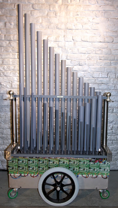
<Hybr>
an electroacoustic pipe organ using membrane driven pipes
Godfried-Willem RAES
2014-2015
|
<Hybr>
|
<Hybr>
Link naar webpagina in het nederlands
When we first designed the Singing Bicycle Project
in 1976,
calling it our 'Second Symphony' with some irony, we calculated a
series of 24 pipes such that they would all be tuned to ideal harmonics
of one single fundamental pitch. Each pipe was excited by an
impedance matched loudspeaker driven by the bicycle dynamo. When
mounted on the bicycle, the resonant frequency of the tube sounds at a
specific speed, different for each bicycle. The piece
was conceived as using 'just
intonation' and hence the pipe lengths were cut to the 24-note series:
182 161 159,5 158 156 153,5 150 146 ,143 140 135,5 130,5 126,5 124
121,5 115,5 110 108 103,5 100,5 98,5 95,5 93,5 85,5 covering an
interval of an octave and a fifth. Although the symphony has been
performed over a hundredth
times since 1980, we never actually verified the acoustic and harmonic
result against what we theoretically conceived...
In 2014 we performed a series of precise measurements and -not really amazing-
found out that the initial concept belongs in the land of fairy tales. We were
not really amazed because in the last twenty years we have been involved quite
deeply into acoustic research on musical instruments and robotics. This research
led us to the conviction that there is not such a thing as 'harmony' or 'just
intonation' anywhere in the world of acoustics, be it strings, pipes ,let alone
more 3-dimensional vibrating objects.
Loudspeakers driving cylindrical tubes in fact form a pretty complex acoustic
system. The traditional acoustic theory with regard to open and closed pipes,
does not seem to apply here. The pipes do not function merely as resonators,
but are an integrated part of a complex oscillating system. The one end, closed
by the loudspeaker does neither behave as a closed nor as an open end. The loudspeaker
here behaves as a membrane driven in its center and shows off a highly nonlinear
response curve. Thus we have to do with two mutually dependent vibrating systems.
The table below gives the results of a long series of measurements, revealing
this clearly.
Setup for the experiment:
Visaton loudspeaker, Type K50WP, 50 Ohms, 3 W. Frequency response 180-17000
Hz. Resonant frequency 300 Hz. For details and specifications, see
spec. sheet. The response curve looks like this: 
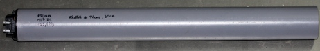
PVC Pipe 50 mm diameter (internal 46 mm), fault 0.1 mm. Measurement
fault on pipe lengths: 0.5 mm. The speakers were glued firmly and
airtight to the tubes using PVC cement glue. (Tangit). Here is an example:
The first column in the table gives the pipe length. The second columns gives
the ratio length to internal diameter. The third column gives the resonant frequency
for such a tube resonating at 1/4 wavelength and with end correction applied
according to the textbook formula found in most books on acoustics :  The fourth column gives the lowest resonant frequency as measured by sweeping
the oscillator from near 0 Hz upwards. The next columns give the measured frequencies
of the next clearly discernible overtones as well as their ratio to the fundamental.
The excitation was always a pure sinewave.
The fourth column gives the lowest resonant frequency as measured by sweeping
the oscillator from near 0 Hz upwards. The next columns give the measured frequencies
of the next clearly discernible overtones as well as their ratio to the fundamental.
The excitation was always a pure sinewave.
| Physical pipe length | l/d | fres calc |
f0 | f1, f1/f0 | f2, f2/f0 | f3 , f3/f0 |
| 48.5 mm |
1.054 | 353 |
- |
- |
- | |
| 62 mm |
1.35 | 337 |
- |
- |
- | |
| 78.5 mm |
1.71 | 330 |
1008 [3.05] |
2600 [7.88] |
- | |
| 395 mm | 8.59 | 160 |
170 | 362 [2.14] | 664 [3.91] | 1092 [6.42] |
| 451 mm (Mib 51) |
9.80 | 155.6 | 310 [1.99] 340 [2.18] |
583 [3.75] |
933 [5.99] | |
| 465 mm | 10.11 | 151 | 302 [2.00](*) | 574 [3.80] | 916 [6.06] | |
| 583 mm |
12.67 | 129 |
326 [2.52] | 462 [3.58] | ||
| 600 mm |
13.04 | 130 |
323 [2.48] |
489 [3.76] | 989 [7.61] | |
| 627 mm | 13.63 | 121 | 311 [2.57] | 444 [3.66] | ||
| 683 mm |
14.85 | 112 |
296 [2.64] |
316 [2.82] | 633 [5.65] | |
| 700 mm |
15.22 | 108 |
287 [2.66] |
428 [3.96] | 619 [5.73] | |
| 774 mm |
16.83 | 98 |
260 [2.65] |
382 [3.90] |
560 [5.71] | |
| 805 mm |
17.5 | 96 |
287 [2.98] | 385 [4.01] | 950 [9.89] | |
| 847 mm | 18.41 | 90 | 238 [2.64] | 356 [3.95] | 520 [5.77] | |
| 880 mm |
19.13 | 89 |
262 [2.94] | 352 [3.95] |
700 [7.86] 865 [9.72] |
|
| 924 mm |
20.09 | 84.5 |
253 [2.99] | 338 [4.00] | 659 [7.80] | |
| 962.5 mm |
20.92 | 82 |
242 [2.95] | 330 [4.02] | 628 [7.66] | |
| 1005 mm |
21.85 | 78 |
235 [3.01] | 359 [4.6] | 772 [9.89] | |
| 1125 mm |
24.46 | 64 |
189 [2.95] | 250 [3.90] | 296 [4.63] 384 [6.00] |
|
| 1145 mm |
24.89 | 69.5 |
205 [2.94] | 322 [4.63] | 410 [5.89] | |
| 1198 mm | 26.04 | 67 | 201 [3.00] | 311 [4.64] | ||
| 1366 mm |
29.69 | 59 | 175 [2.96] | 277 [4.69] | 356 [6.03] | |
| 1425 mm |
30.98 | 56 | 170 [3.03] | 281 [5.02] | 351 [6.27] | |
| 1562 mm |
33.96 | 53 |
158 [2.98] |
262 [4.94] | 347 [6.55] |
(*) The audible result we observed here is two separate tones, one octave different. The fundamental f0 sounds together with f1.
From the data, it will be clear that around the resonant frequency of the loudspeaker (300 Hz) either pulling or pushing of the total resonance at the corresponding pitch does occur. Below the loudspeaker resonance frequency, the pipes behave pretty well as pipes closed at one end, although even overtones are certainly present. The larger the l/d ratio, the more the overtone series corresponds to a series off odd multiples of the fundamental, except for those overtones that fall in the region of the loudspeaker resonance. Here are some measurements for 25 mm diameter tubes (internal diameter = 22 mm) , mounted on the speakers using a slightly conical adapter:
| length | L / d | f0 | f1, f1/f0 | f2, f2/f0 | f3, f3/f0 |
| 251.5 mm | 11.4 | 169 | 511 [3.02] | 955 [5.65] | 1526 [9.03] |
| 200 mm | 9.09 | 190 | 572 [3.01] | 1150 [6.05] | 1876 [9.87] |
| 186 mm | 8.45 | 196 | 603 [3.08] | 1199 [6.12] | 2026 [10.34] |
| 146 mm | 6.6 | 220 | 695 [3.16] | 1492 [6.78] | 2605 [11.84] |
| 125 mm | 5.68 | 233 | 762 [3.27] | 1715 [7.36] | - |
Measurements were performed using an analog sine wave generator with a digital
frequency counter. Resolution 1 Hz. The output impedance is 50 Ohms and thus
matches the nominal impedance of the drivers. The precision is better than 1%.
Output voltage was kept constant at 3 V rms. for all measurements. For most
tubes, some resonance was also observed around the octave and other even overtones,
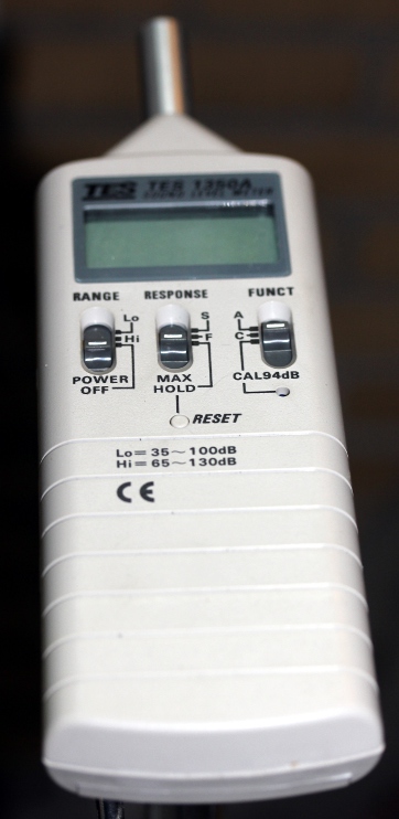
but at a level too low to be easily measured. For measurement of the sound
level and determination of the resonance peaks we used a calibrated sound level
meter placed on a tripod at 30 cm distance from the open end of the tube.
The larger the l/d ratio becomes, the closer the first overtone comes to 3.0
times the fundamental. The second overtone seems to move from 3 times to 5 times
the fundamental. The factor for the third overtone is from our data not
easily discerned. It also seems to increase with increasing tube length.
An important observation was also that the resonant frequency shifts clearly
upwards with increasing excitation amplitude. This may be attributed to a change
in the velocity of sound in function of the pressure in a constricted volume.
The precision of the measurements presented here is not high enough to clearly
prove the inharmonicity of the overtone series, let alone to derive laws on
the underlying math. It is indicative though. Exact measurements would require
1 cent resolution for frequency measurement and hence, say for midi note 36
(f= 65.41) a time interval of at least 400 seconds. Of course the time interval
required for 0.01% precision measurements, halves as the frequency to be measured
doubles. To increase the reliability of our measurements using a function generator
with frequency readout (time base limited to 1 second, hence frequency resolution
= 1Hz), we used a Korg tuner with an analog readout and a precision of ca. 2
cents. This precision though is only valid for frequencies conforming to the
scale of equal temperament at a given diapason (here set to 440 Hz). We had
a Hameg function generator with a 0.1 Hz resolution on the read out available
as well, but this piece of equipment makes use of digitally generated sine waves
and hence the frequency runs up stepwise, preventing us to hit the exact resonance's.
We used the measurement data for 50 mm tubes to obtain a third degree equation, using a Gauss fit procedure. The equation becomes:
freq = 309.048 - 0.4617146 * x + 3.013809E-04 * x^2 - 7.109726E-08 * x^3
The tube length (x) is expressed in mm.
A 6th degree equation, obtained with a Gaussfit program calculated over 20 data pairs taken in the length traject between 395 mm and 1582 mm leads to errors less than 1%. It looks like this:
freq = 317.6497 -.4827873 x + 2.720424E-04 x^2 +
2.693052E-08 x^3 -5.110973E-11 x^4 -1.656992E-14 x^5 +
1.248304E-17 x^6
Apparently, this approach does not seem to lead to a better understanding of
the laws governing our observations, however it is quite useful for the calculation
of pipe lengths extrapolated for parameters within the range of the data set
as long as this data set is kept narrow.
As the sound produced by these resonating tubes was pretty 'acoustic' in nature, we decided to design and build an automated instrument based entirely on this principle. The electric excitation signal is by default pure sinusoidal, but the waveform produced by the pipes at resonance is by far not a sinewave but contains quite a broad and varying spectrum clearly produced by the non linear behavior of the pipe resonators. We baptized it 'Hybr' since the design is somewhere in between an electronic and an acoustic instrument. Each pipe is controlled by an individual oscillator of which excitation amplitude, envelope and microtuning can be fully controlled via MIDI commands. The experimentally determined overtones for each pipe can be added to the sine wave fundamental in programmable amplitude proportions. A form of inharmonic additive synthesis one could call this. To this end we called in no less then 20 ARM 32 bit microprocessors (STM32F407) as each processor is capable of generating only two independent drive signals. The timbre of the instrument is characterized by a low formant frequency of 300 Hz, caused by the resonant frequency of the loudspeakers. Of course this only holds for pitches below the resonant frequency.
The instrument belongs to the category of the organs. In traditional organ
building, membrane driven pipes have been used occasionally in the 19th century:
the diaphone stop, mentioned and described by Audsley, is an example. This instrument
however, is quite different and offers many more possibilities, as the resonance
of the pipes can be fully controlled through electronic means. An important
advantage over any other organ-type instrument is that here we can have a very
broad control over dynamics, the tuning of the pipes being independent of wind
pressure. The global sound volume can be controlled as well as the individual
loudness of each individual pipe. Moreover, our implementation makes it possible
to use the instrument in just about any imaginable tuning system, as each pipe
can be detuned a quartertone up or down referred to equal temperament intonation.
Definitive pipes as made, tuned and measured::
| f0 | l/d | f1 | f2 | f3 | L | De | Di | SPL | f1m |
f2m |
|
| 33 |
55.0 |
31.8 |
165 [3.00] |
219 [3.98] |
270 [4.91] |
1461 |
50 |
46.4 |
68 | 52.01 |
56.92 |
| 34 |
58.3 |
29.9 |
175 [3.00] |
233 [4.00] |
288 [4.94] |
1378 |
50 |
46.4 |
78 | 53.03 |
57.99 |
| 35 |
61.7 |
28.2 |
183 [2.96] |
245 [3.97] |
286 [4.63] |
1295 |
50 |
46.4 |
77 | 53.81 |
58.86 |
| 36 | 65.4 | 26.4 | 195 [2.98] |
258 [3.94] | 306 [4.68] | 1216 | 50 | 46.4 | 81 | 55.91 |
59.76 |
| 37 | 69.3 | 24.8 | 210 [3.03] |
274 [3.95] |
323 [4.66] |
1142 | 50 | 46.4 | 76 | 56.19 |
60.80 |
| 38 | 73.4 | 23.3 | 218 [2.97] |
291 [3.96] |
344 [4.68] |
1073 | 50 | 46.4 | 82 | 56.84 |
61.84 |
| 39 | 77.8 | 21.8 | 235 [3.25] | 359[4.61] | 772 [9.92] | 1005 | 50 | 46.4 | 58.14 |
65.48 |
|
| 40 | 82.4 | 20.5 | 244 [2.96] | 330 [4.00] | 468 [5.68] | 949.5 | 50 | 46.4 | 82 | 58.79 |
64.02 |
| 41 | 87.3 | 19.9 | 262 [3.00] | 352 [4.03] | 700 [8.02] | 880 | 50 | 46.4 | 60.02 |
65.14 |
|
| 42 | 92.5 | 17.9 | 274 [2.96] |
377 [4.08] | 523 [5.65] |
833 | 50 | 46.4 | 82 | 60.80 |
66.32 |
| 43 | 98.0 | 16.8 | 193 [1.97] | 260 [2.65] | 384 [3.92] | 780.5 | 50 | 46.4 | 86 | 54.73 |
59.89 |
| 44 | 103.8 | 16.6 | 202 [1.95] |
271 [2.61] | 412 [3.97] | 732 | 50 | 44 | 88 | 55.52 |
60.61 |
| 45 | 110.0 | 15.6 | 212 [2.02] |
291 [2.64] | 428 [3.89] |
686 | 50 | 44 | 88 | 57.16 |
61.84 |
| 46 | 116.5 | 14.6 | 231 [1.98] |
312 [2.68] |
444 [3.82] | 643 | 50 | 44 | 84 | 57.84 |
63.04 |
| 47 | 123.5 | 13.7 | 246 [1.99] |
328 [2.66] | 460 [3.72] | 601 | 50 | 44 | 88 | 58.93 |
63.91 |
| 48 | 130.8 | 12.8 | 262 [2.00] |
342 [2.61] |
484 [3.7] | 563.5 | 50 | 44 | 90 | 60.02 |
64.64 |
| 49 | 138.6 | 11.9 | 286 [2.06] |
356 [2.57] | 614 [4.43] | 523.5 | 50 | 44 | 91 | 61.54 |
65.33 |
| 50 | 146.8 | 11.1 | 302 [2.06] |
642 [4.37] |
858 [5.84] | 488.6 | 50 | 44 | 89 | 62.48 |
75.54 |
| 51 | 155.6 | 9.8 | 310 [1.99] | 340 [2.18] | 583 [3.74] | 451 | 50 | 46.4 | 62.94 |
64.50 |
|
| 52 | 164.8 | 10.9 | 341[2.07] | 651[3.95] | 1035 [6.28] |
405 | 40 | 37 | 88 | 64.58 |
75.78 |
| 53 | 174.6 | 9.8 | 387 [2.21] |
725 [4.15] |
1160 [6.64] | 362 | 40 | 37 | 93 | 66.77 |
77.64 |
| 54 | 185 | 9.5 | 395 [2.13] |
739 [3.99] | 1199 [6.45] |
352 | 40 | 37 | 87 | 67.13 |
77.98 |
| 55 | 196 | 9.3 | 497 [2.53] |
996 [5.08] | 1596 [8.14] | 263 | 32 | 28.4 | 93 | 71.11 |
83.14 |
| 56 | 207.6 | 7.7 | 549 [2.64] |
1146 [5.52] | 1848 [8.90] | 220 | 32 | 28.4 | 89 | 72.83 |
85.57 |
| 57 | 220 | 7.3 | 545 [2.48] |
1196 [5.44] | 1964 [8.92] | 208 | 32 | 28.4 | 72.70 |
86.31 |
|
| 58 | 233.1 | 6.18 |
763 [3.27] | 1024 [4.39] | 1728 [7.41] |
132.2 | 25 | 21.4 | 92 | 78.51 |
92.55 |
| 59 | 246.9 | 4.97 | 840 [3.4] |
1900 [7.69] | - | 109.5 | 25 | 22 | 83 | 80.19 |
94.33 |
| 60 | 261.6 | 51.0 | 466 [1.78] |
664 [2.54] | 863 [3.30] | 689 | 20 | 17 | 83 | 69.99 |
76.12 |
| 61 | 277.2 | 38.3 | 470 [1.69] |
682 [2.46] |
900 [3.25] | 652 | 20 | 17 | 86 | 70.14 |
76.59 |
| 62 | 293.7 | 35.7 | 513 [1.75] |
726 [2.47] |
962 [3.27] | 607 | 20 | 17 | 71.66 |
77.67 |
|
| 63 | 311.1 | 33.2 | 538 [1.73] |
768 [2.47] |
1004 [3.22] | 565 | 20 | 17 | 86 | 72.48 |
78.64 |
| 64 | 329.6 | 30.0 | 606 [1.84] | 978 [2.97] | 1129 [3.43] | 511 | 20 | 17 | 74.54 |
82.83 |
|
| 65 | 349.2 | 28.1 | 628 [1.80] | 909 [2.6] | 1206 [3.46] | 478 | 20 | 17 | 75.16 |
81.56 |
|
| 66 | 370 | 26.5 | 658 [1.78] | 936 [2.53] | 1243 [3.36] | 451 | 20 | 17 | 83 | 75.97 |
82.07 |
| 67 | 392 | 31.4 | 711 [1.81] |
973 [2.48] | 1312 [3.35] | 427 | 16 | 13.6 | 77.31 |
82.74 |
|
| 68 | 415.3 | 29.0 | 750 [1.81] |
1005 [2.42] | 1368 [3.3] | 395 | 16 | 13.6 | 78 | 78.23 |
83.30 |
| 69 | 440.0 | 27.2 | 764 [1.74] |
1063 [2.42] | 1450 [3.3] | 370 | 16 | 13.6 | 78.55 |
84.27 |
|
| 70 | 466.2 | 25.2 | 776 [1.66] |
1104 [2.37] | 1544 [3.31] | 342 | 16 | 13.6 | 85 | 78.82 |
84.93 |
| 71 | 493.9 | 23.4 | 820 [1.66] | 1186 [2.4] | 1665 [3.37] | 318.1 | 16 | 13.6 | 86 | 79.78 |
86.17 |
| 72 | 523.2 | 21.3 | 893 [1.70] |
1325 [2.53] |
1866 [3.56] | 290.2 | 16 | 13 | 87 | 81.25 |
88.09 |
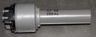
Pipe 58, driven at resonance with our sine wave generator, shows up a 4.94 Vrms voltage across the speaker terminals. Power delivered to the speaker hence is 500 mW. The sound pressure level produced by the pipe is 92 dBA measured at 30cm distance from the open end of the pipe.
For all pipe diameters smaller than 50 mm, we used a conical adapter piece.
This fundamentally changes the acoustic behavior of the system, as it introduces
a third interacting resonator between the speaker and the pipe. The own frequency
of this system was found out to be situated between 80 Hz and 108 Hz,
the exact value going down with increasing length of the coupled pipe. We could
only avoid this by using speakers of decreasing diameters. Unfortunately, they
do not seem to exist. Speaker systems for headphones and earplugs do exist
in small diameters down to 10 mm, but their power rating is limited to 100 mW.
One of the reasons we selected the Visaton speakers of the type specified in
this project is that they have mylar membranes and not cardboard, thus they
are to a certain extend weather and moisture resistant. The only issue is that
the pipes have to be kept free from objects, dust and granulates falling into
them, as this will affect the sound. Turning the instrument upside down
and gently shaking it will be the cure.
Midi implementation and mapping:
Midi channel: 8 (counting 0-15)
Note Off: notes 33 to 72 , note release implemented.
Note On: notes 33 to 72 , velo implemented.
Lights:
Keypressure: used to modulate the pitch of each individual sounding note. Value=64 gives standard pitch, values 63 to 0 bend the pitch down, values 64 to 127 bend upwards. The range is 50 cents up or down. This implementation makes it possible to play the instrument in just about any imaginable microtuning. The value of the individual note microtuning settings is 'sticky', thus users do not have to send it with every note on command. A note-off command will not reset the microtuning of the corresponding note. This implementation deviates from standard midi! Before using aftertouch, controller 124 should be set to value 64 to acquire the right scaling! Once this controller is set, each note should be initialized with it's right aftertouch.
Controllers:
#1: Wind noise or pitch instability. (Default value 0)
#3: Vibrato depth (FM) (default value 0)
#4: Vibrato speed (FM) (default value 0)
#5: Tremolo depth (AM) (default value 0)
#6: Tremolo speed (AM) (default value 0)
#7: global volume (default value 64)
#16: global attack control (attack time) (default value 1)
#17: global maximum velo amplitude
(default value 127)
#18: global decay time (default value 1)
#19: global release time (default value 1)
#20: Global tuning (range, a quartertone up or down). Default value 64 for A=
440 Hz (*)
#23 to # 62: Amplitude of the first inharmonic overtone on pipes for notes
33 to 72. The frequencies for these overtones correspond with the pipe table
given above. (Default values 0)
#66: Power on/off switch. Power off disables the amplifiers by muting them but
does not unpower them. Power off resets all controllers to their startup default
values. When the <Booter> is used, all midi-files for Hybr and HybrHi
should start by sending this controller and end by sending this controller with
value 0. This will effectively cold-boot both Hybr and HybrHi. Note that there
is a 1.5 second delay during which the robots will be blind for midi-commands.
#67: Volume control for the common external audio input (default value 0)
#73 to #112: Amplitude of the second inharmonic overtone for notes 33
to 72. The frequencies appear in the pipe table given above. (Default values
0)
#123: all notes off, preserving all controller settings including microtuning.
#124: initialization of key-pressure. In case key-pressure is used, this controller
should be set to value 64. Once this controller is set, keypressure for all
notes should be set to 64 for all notes for normal pitch. In case no key-pressure
is used, this controller should not be set.
(*) If the tuning is set much different from 440Hz, the overall amplitudes will be affected, unless tuning follows the changes of resonance frequencies as a result of temperature changes. The range is a quartertone up or down. Parameter value 64 equals A=440Hz)
Controller #13 can be used to change the waveform of the excitation.
Channel aftertouch and pitch bend are not implemented on <Hybr>.
Channel aftertouch would not be very meaningful for such a polyphonic instrument
and pitch bend is contrary to the acoustic nature of the instrument. Moreover,
global small pitch inflections can be performed using the tuning controller.
Polyphonic pitch inflections can be performed by using he keypressure command.
In addition to the features described before, we implemented an operational
mode wherein the instrument can be used as an acoustic fourrier transformer
with equal tempered frequency bins. Therefore it is required to feed all
40 loudspeakers with one and the same audio signal, limited in bandwidth (fc=
1500 Hz) to the range of the instrument. The sampling rate for this channel
is pretty low (>= 3 kS/s) and the resolution is 12 bits. The common audio
drive input requires a low impedance (< 600 Ohm) line level signal.
The level of this signal as presented to the pipes can be controlled with midi
controller #67.
The design of this instrument may give rise to a lot of practical applications
even in traditional organ building. In this project we used only cylindrical
pipes, but obviously pipe shapes such as used in traditional pipe organs can
be used as well, making it possible to have full sets of registers or stops.
The advantage of such membrane driven pipes in traditional organs being that
they are by design to a much higher degree free of maintenance as they
do not require periodic tuning. Also, this technology is inherently free of
wind noise caused by leaks as well as compressor motor noise.
A word of warning to our users: by design, electrically overloading the speakers
such that they burn out is almost impossible. The same applies to the amplifiers.
However, due to the resonance's occurring in the pipes, it is very well possible
to ruin the speakers by excessive sound volumes. This occurs whenever the membrane
displacement due to mechanical resonance exceeds the allowable maximum. As this
limit is approached, a clear change in sound quality (distortion) will be observed.
This should be understood as an imperative to reduce the volume, either by sending
a lower setting for controller #7 (volume), or by using lower velocity values.
Technical specifications:
Music composed for <Hybr>:
Godfried-Willem Raes 'Namuda Study #49: Hybr', premiere January 13th 2015 by Dominica Eyckmans and Emilie De Vlam..
Godfried-Willem Raes 'Namuda Study #57: Tekstuur', premiere October 28th 2015 by Dominica Eyckmans.
Godfried-Willem Raes 'Bottom Boot', premiered september 2016 by Emilie De Vlam (This performance also includes <HybrHi> and <HybrLo>).
Kristof Lauwers 'Study for Hybr', 2015
Xavier Verhelst
| Back to Logos-Projects page : projects.html | Back to Main Logos page:index.html | To Godfried-Willem Raes personal homepage... | To Instrument catalogue |  |
Construction diary:
03.10.2014: Construction of the first test-pipes based on the new designs for
the Singing Bicycle Symphony.
04.10.2014: Construction of some prototype pipes with different diameters. Gray
PVC pipe diameters we can easily get are 50 mm, 40 mm, 32 mm, 25 mm, 20 mm.
The performed measurements lead us to design the pipes such that the ratio pipe-length
to internal diameter stays larger than 9. A first version of a pipe calculation
utility is programmed and debugged. 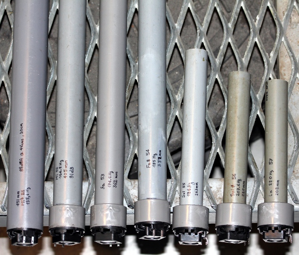
05.10.2014: More prototype pipes build and measured. Interesting discovery:
the resonant frequency depends on the excitation level.... It goes up with increasing
sound pressure. Furthermore, the curve of resonance is not at all symmetrical.
It has a slower slope rising than descending.
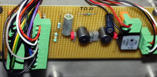
06.10.2014: Design of a power amplifier to drive the speakers. Here is
our first circuit:  Note that all audio-in inputs are connected together such that all amps can
be operated with a single audio signal. In this mode, the instrument operates
as a chromatic spectrum transformer. The input impedance for this common input
is 550 Ohms. The AXO input, connects to one of the two audio outputs of the
digital synthesis boards using an ARM processor. The ANA input is used to connect
to the outputs of individual analog modified sine wave generators. The diodes
over the output terminals protect the amp against voltages higher than the supply
voltage as these do occur at resonance over the speakers. However, we need at
least 38 of these amps... A calculation of the costs leads to ca. 30 Euro per
channel, so the total bill runs up to 1.200 Euro. As an alternative, we could
also use ready made 4-channel car amplifier modules as produced by BaseTech,
type AP-4012. The specs are 4 x 11.5 W rms output power. We ordered 10 such
modules from Conrad at 25 Euro's a piece. So, this brings this part of the costs
down to 250 Euro. There is no way to solve this problem cheaper by any design
we could think of. The power supply for all these amplifiers should be rated
for 10 A at 12 V DC.
Note that all audio-in inputs are connected together such that all amps can
be operated with a single audio signal. In this mode, the instrument operates
as a chromatic spectrum transformer. The input impedance for this common input
is 550 Ohms. The AXO input, connects to one of the two audio outputs of the
digital synthesis boards using an ARM processor. The ANA input is used to connect
to the outputs of individual analog modified sine wave generators. The diodes
over the output terminals protect the amp against voltages higher than the supply
voltage as these do occur at resonance over the speakers. However, we need at
least 38 of these amps... A calculation of the costs leads to ca. 30 Euro per
channel, so the total bill runs up to 1.200 Euro. As an alternative, we could
also use ready made 4-channel car amplifier modules as produced by BaseTech,
type AP-4012. The specs are 4 x 11.5 W rms output power. We ordered 10 such
modules from Conrad at 25 Euro's a piece. So, this brings this part of the costs
down to 250 Euro. There is no way to solve this problem cheaper by any design
we could think of. The power supply for all these amplifiers should be rated
for 10 A at 12 V DC.
07.10.2014: Purchase of extra lengths 50 mm PVC tube. Construction, measurement
and fine tuning of pipes for A 33, Bb 34, B 35. This is our testing set
up: 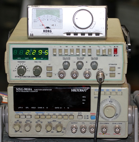 Thick
(25 mm) PVC plate material ordered from Eriks for the construction of the 'windchest'
and pipe holder. Sketches made for the possible final design. Looks like it
will have to become a six-wheeler, as we have to keep building height to the
minimum required. Designing utility program for the calculation of the pipes
much improved.
Thick
(25 mm) PVC plate material ordered from Eriks for the construction of the 'windchest'
and pipe holder. Sketches made for the possible final design. Looks like it
will have to become a six-wheeler, as we have to keep building height to the
minimum required. Designing utility program for the calculation of the pipes
much improved.
08.10.2014: Ten more pipes tuned and measured. As we run out of stock in 50
mm 1.8 mm thick pipe, we now use 50 mm 3 mm thick pipe material.
09.10.2014: Experiments performed with 32 Ohm speaker drivers from headsets.
The power specifications for these are only 100 mW, but their diameter is more
suitable for the smaller pipes. Sound pressure meter as used for our measurements:
10.10.2014: <Hybr> project temporarily postponed because of too many interfering
projects.
11.10.2014: Some pictures of the pipes made so far: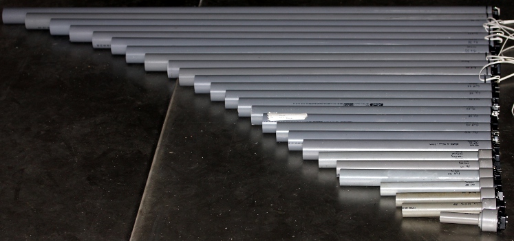
20.10.2014: Further work on the sketches for the robot.
25.10.2014: The ordered conical PVC adapter pieces as well as PVC pipe in smaller
diameters came in from Eriks. We can continue building and tuning pipes.
26.10.2014: Twenty Axo boards commissioned from Johannes Taelman.
29.10.2014:
Construction and measurement of pipes in 10 mm, 12 mm, 16 mm
and 20 mm diameters, with cones to couple them to to 50 mm speakers.
Data
sets added to our calculation software for Hybr. For the highest pipe
we will go for 16 mm outer diameter, although even 12 mm leads to a
good
sounding pipe, be it somewhat softer. Discovery that with a
conical piece and coupled to pipes much smaller than the loudspeaker
diameter, the pipes behave acoustically as half wave resonators,
so as pipes open at both ends. The spectrum observed is
compressed. This applies to 16 mm and 20 mm pipes.
30.10.2014: Extra PVC adapter pieces ordered from Eriks. Still waiting for the
thick PVC plates to flow in. All 16 mm diameter pipes finished. Four 20 mm pipes
ready. Calculation software adapted and measurement data entered. Here is a
picture of the highest nine pipes: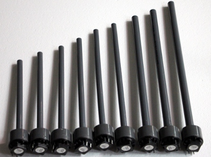 Six 16 mm pipes and three 20 mm pipes.
31.10.2014: Design of the electronic circuitry. Decision to make use of 20 ARM
STM32F4 discovery boards, each board steering two pipes. Design of a PC board
to mount two of the boards on a single Eurocard with Weidmueller connector for
5 V and Midi, as well as a common analog input rail.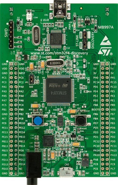 The 1/8" stereo output jacks will be unsoldered and the connections redone using
wires. A single Eurocard will then control four notes. The documentation for
the ARM board is on the website: http://www.st.com/stm32f4-discovery. The software
platform we will use to develop the firmware is Johannes Taelman's Axoloti project.
The 1/8" stereo output jacks will be unsoldered and the connections redone using
wires. A single Eurocard will then control four notes. The documentation for
the ARM board is on the website: http://www.st.com/stm32f4-discovery. The software
platform we will use to develop the firmware is Johannes Taelman's Axoloti project.
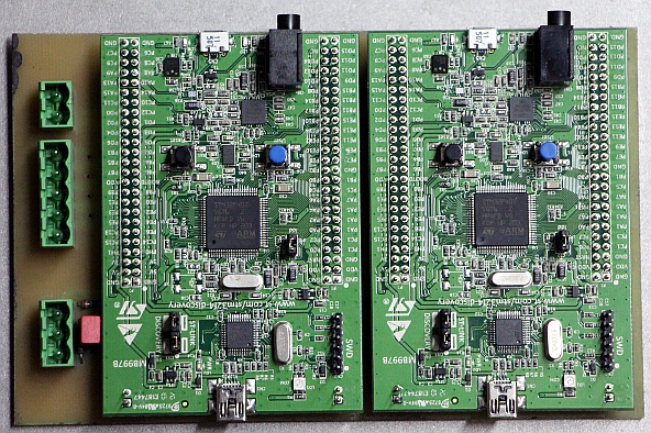
01.11.2014: Mounting PC board, Eurocard size, drawn to accommodate two ARM-discovery
boards. Thus each board will have four note outputs and connects to its own
four-channel power amp. Ten of these board will be required. Etching will be
for tomorrow or later... The board (reduce to 25% for printing) can
be downloaded here. As -by design- we have only 1000 mm width available
for mounting, we decided to mount the board on swivels, such that they can be
folded out for programming. If we mount them flat, the USB connectors required
for uploading the firmware would become inaccessible
02.11.2014: Fifty cheap RCA phono plug connectors as well as two row 2.54 mm
sockets for the ARM boards ordered from Farnell. Twenty small hinges bought
on the flea market to be used for mounting our PC boards. Technical construction
drawing worked out. It looks like it will be hard to keep the building height
below 2 meters... Anyhow, that's still about 10 cm smaller than <Krum>...
03.11.2014: Start construction of the chassis: cutting and drilling
stainless steel 40 x 40 x 4 T profile and plate material 325 x 1000 x 3 mm. Central
wheels will be 400 mm diameter. PVC adapter pieces delivered by Eriks.
04.11.2014: All 40 pipes finished now. Pipes 33 to 59 behave (more
or less) as 1/4 wavelength resonators, pipes 60-72 as 1/2 wavelength
resonators.
05.11.2014: Etching, drilling and soldering of the ten PC boards for
the ARM-processors started. Etching takes longer than we
thought...Two boards completed so far.
06.11.2014: All boards exposed to UV and developed. Eight boards
etched... more to come. A day of drilling in sight. Firmware discussion
with Kristof Lauwers. Mattias Parent called in to help out with the
drilling.
 . This is the solder side of those boards:
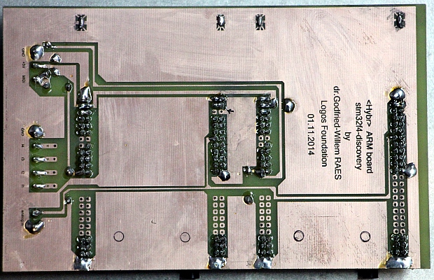
08.11.2014: Drilling and threading of the holes and M4 threads for the power amplifiers.
09.11.2014: Further soldering work on the boards.
10.11.2014: Running out of connectors. New order placed at Farnell.
Five boards finished now. Halfway that means. These can already
be programmed.
11.11.2014: TIG-Welding works on the chassis parts.
12.11.2014: Already six ARM boards mounted on hinges. Still waiting for
the thick PVC plates to make the pipe carrier plate. Nine boards
soldered and ready.
13.11.2014: Two more PC boards for the ARM processors exposed,
developed, etched and drilled. T-profiles welded to the large chassis
plates. Start mounting of the power supply components. Fresh load of
connectors came flowing in from Farnell.
14.11.2014: Start assembly of the power supply components. We stick to
pure analog here, avoiding all spurious noises that could be caused by
switch-mode power supplies. For both power supply voltages we make use of toroidal transformers.
15.11.2014: Wiring and testing of the power supplies.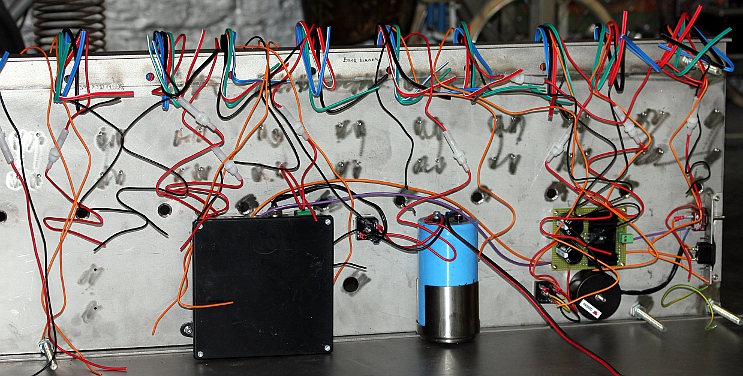
17.11.2014: All 10 quad power amps mounted on the back plate.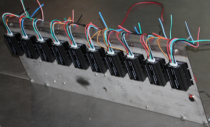 All BaseTech amps mounted with M4 x 10 stainless steel bolts. Threads for the hinges finished
on the front plate. Here we have to use M4 x 6 countersunk bolts.
All BaseTech amps mounted with M4 x 10 stainless steel bolts. Threads for the hinges finished
on the front plate. Here we have to use M4 x 6 countersunk bolts.
19.11.2014: Further tedious soldering work on the ARM carrier boards. Should be finished by the end of the day...
20.11.2014: Development task for the Axoloti patches for the ARM processors
confined to Kristof Lauwers, with assistance from Johannes Taelman, who developed
the firmware. For the wiring, we will call in the help of Mattias Parent. In
the meanwhile, starting soldering of the midihub board. Still waiting
for the thick PVC material for the 'windchest'...
21.11.2014: Start writing test and debugging code in GMT.
22.11.2014: First tentative mount of the two large plates together.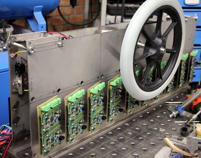 Presenting the wheels, after cutting the spindle. Start construction of the
holders for the small wheels. Seems we drilled the holes for the midihub board
on the wrong side of the panel... Looks like we will have to leave it there,
as changing it involves removing all the ARM boards again...
Presenting the wheels, after cutting the spindle. Start construction of the
holders for the small wheels. Seems we drilled the holes for the midihub board
on the wrong side of the panel... Looks like we will have to leave it there,
as changing it involves removing all the ARM boards again...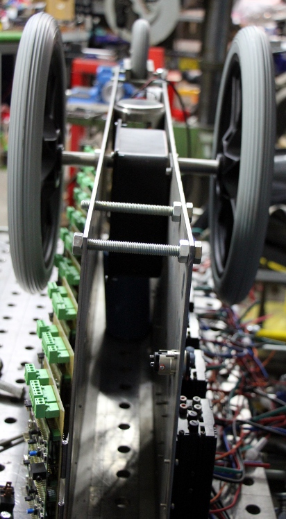 The space between the two plates is exactly 96 mm. News came from Eriks: the
PVC plate material should be delivered on Monday...
The space between the two plates is exactly 96 mm. News came from Eriks: the
PVC plate material should be delivered on Monday...
23.11.2014: Continuing welding work on the small wheel holders. Looks like we
will be running out of Argon gas soon...
24.11.2014: Finishing the small wheel holders. Order for extra wheels 125 x
35. Design of a polycarbonate protective plate for the frontal boards. Awaiting
the delivery of the PVC plates... Firmware development by Kristof Lauwers. Continuing
development of test code in GMT. Work session with Johannes Taelman. The PVC
plates came in and so we could start the drilling of the holes in the pipe holder.
The 50 mm holes pose some problem as the PVC melts in the hole saw and makes
it very hard to remove the center from the saw. There must be a trick. Cooling
with frozen CO2 didn't seem to help very much.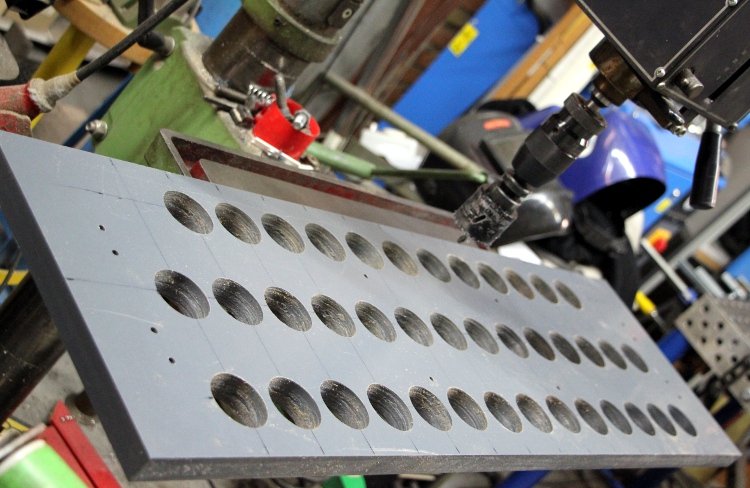
25.11.2014: All 40 holes drilled and carefully honed to 50 mm. First two rows
of pipes glued to the pipeholder. Rebuilding pipe for note 58 , using the same
conical adapters as adjacent pipes. This pipe is now from 1.8 mm thick pipe
and thus the length became a bit longer than that of the first made pipe.
Lookup table adapted accordingly.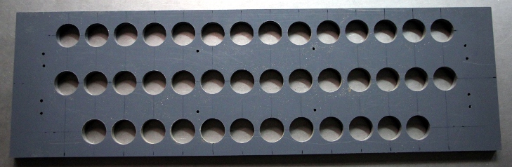
26.11.2014: All pipes glued to the pipeholder plate. Upper pipe holder for the
longest pipes cut from 25 mm thick PVC. This measures 1000 x 100 x 25 mm and
has 14 holes, diameter 50 mm. 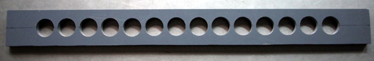 Decided
to use connectors between the speakers and the amplifier outputs as otherwise
it seems pretty impossible to take the automate apart for repair and maintenance.
First 30-pole connector mounted for the highest pipe rank. Two times 3 contacts
remain uncommitted but may be used for 12 V lights on the pipeholder.
Extra 125 mm diameter spoke wheels ordered from Tente.
Decided
to use connectors between the speakers and the amplifier outputs as otherwise
it seems pretty impossible to take the automate apart for repair and maintenance.
First 30-pole connector mounted for the highest pipe rank. Two times 3 contacts
remain uncommitted but may be used for 12 V lights on the pipeholder.
Extra 125 mm diameter spoke wheels ordered from Tente.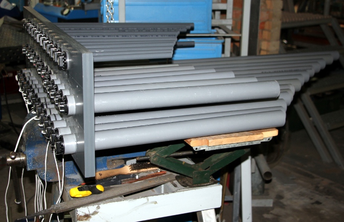
27.11.2014: Start wiring of the loudspeakers and amplifiers. By the end of the
day, we got almost halfway the wiring of the speakers and connectors on the
pipeholder. The construction of the holders for the connectors took a lot of
time. We used two 30 pole 3-row connectors taken from the telephone exchange
company and one Bulgin 36 pole connector as used in our very first version of
the player piano. 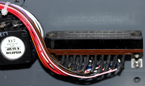 We
also constructed two lights on the top of the pipeholder. The lights have E14
(mignon) sockets and should get 15 V/ 4 W bulbs. It will be possible to
take of the entire pipeholder assembly from the stainless steel chariot just
by loosening the three connectors and the bolts holding the robot together.
We
also constructed two lights on the top of the pipeholder. The lights have E14
(mignon) sockets and should get 15 V/ 4 W bulbs. It will be possible to
take of the entire pipeholder assembly from the stainless steel chariot just
by loosening the three connectors and the bolts holding the robot together.
28.11.2014: DIN916 BIZK RVS-A1 rings bought at MEA. Mid row speaker wiring to
connector finished. 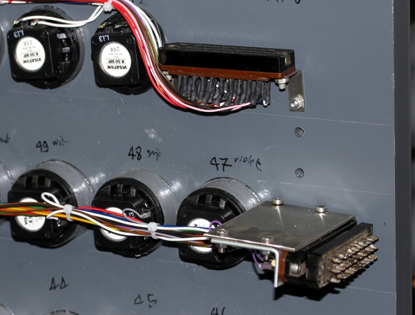 Wiring
for the Bulgin connector on the last row drawn out.
Wiring
for the Bulgin connector on the last row drawn out.
29.11.2014: Wiring of all speaker connectors finished. 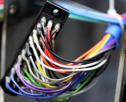 12
V and 24 V bulbs with E14 fittings ordered from Conrad. Common ground line constructed
for all ten power amps. Common +12 V line made as well. These lines are made
of 4 mm2 copper wire. We preserved the individual fuses in the positive power
line of each individual amplifier. As the datasheet for the BaseTech amplifiers
do not specify much, and we wanted to make sure not to blow all of them by connecting
them to our non-stabilised power supply, we opened one to see what chips are
used: two STA540 quad amplifier chips, each connected in bridge. The maximum
supply voltage for these chips under operating conditions is 22 V, so we are
safe with our 17 V peak power supply. Quiescent current is typical 80 mA, so
with ten BaseTech amps, each using two chips, we should count on a quiescent
current of no less than 1.6 A. The input filtering provided on the BaseTech
amplifiers make use of a single TLO84 quad opamp chip.
12
V and 24 V bulbs with E14 fittings ordered from Conrad. Common ground line constructed
for all ten power amps. Common +12 V line made as well. These lines are made
of 4 mm2 copper wire. We preserved the individual fuses in the positive power
line of each individual amplifier. As the datasheet for the BaseTech amplifiers
do not specify much, and we wanted to make sure not to blow all of them by connecting
them to our non-stabilised power supply, we opened one to see what chips are
used: two STA540 quad amplifier chips, each connected in bridge. The maximum
supply voltage for these chips under operating conditions is 22 V, so we are
safe with our 17 V peak power supply. Quiescent current is typical 80 mA, so
with ten BaseTech amps, each using two chips, we should count on a quiescent
current of no less than 1.6 A. The input filtering provided on the BaseTech
amplifiers make use of a single TLO84 quad opamp chip.
30.11.2014: Finishing of midihub board. Firmware version 1.0 written and flashed
into the microcontroller. Board mounted on the chassis.  Wiring can continue... Some 40 RCA connectors soldered. All 5 V power and midi
lines wired from hub board to ARM boards. By the end of the day, 85% of all
wiring finished. Power tests performed. No failures.
Wiring can continue... Some 40 RCA connectors soldered. All 5 V power and midi
lines wired from hub board to ARM boards. By the end of the day, 85% of all
wiring finished. Power tests performed. No failures.
01.12.2014: Finishing wiring: signal input connectors and audio input lines.
Drilling of the two ground connection holes, one for mains ground connection,
one for the negative 12 V supply line. Start construction of the audio-input
board. Reichelt elektronik still has our connectors in their catalogue: FL830,
Federleiste, 30-polig DIN41622. This is a picture of our male parts: 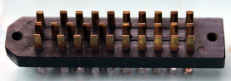 These are rated for 8 A current per contact. Audio input board calculated and
assembled. This is the circuit:
These are rated for 8 A current per contact. Audio input board calculated and
assembled. This is the circuit:  The board measures 160 mm x 60 mm and is to be mounted on the outside of the
backpanel. Nominal input signal level is 0 dB (775 mV rms). Input impedance
is 600 Ohm. Maximum allowable signal: +6 dB (1.5 V rms or 4.3 Vpp), above this
level clipping will occur. The input and output impedance of the Butterworth
filter is 582 Ohms. At the output this is achieved by the parallel resistance
of the 680 Ohm resistor and the load formed by the 20 ARM input impedance. At
the input side it is achieved with the transformer. The outputs of the circuit
have a DC offset of 1.5 V in order to accommodate the ARM inputs which have
a 3.3 V range. We performed some measurements on our circuit and noticed it
causes second harmonic distortion of the waveform on frequencies below 100 Hz
if driven at full amplitude. By the end of the day, all wiring was done...
The board measures 160 mm x 60 mm and is to be mounted on the outside of the
backpanel. Nominal input signal level is 0 dB (775 mV rms). Input impedance
is 600 Ohm. Maximum allowable signal: +6 dB (1.5 V rms or 4.3 Vpp), above this
level clipping will occur. The input and output impedance of the Butterworth
filter is 582 Ohms. At the output this is achieved by the parallel resistance
of the 680 Ohm resistor and the load formed by the 20 ARM input impedance. At
the input side it is achieved with the transformer. The outputs of the circuit
have a DC offset of 1.5 V in order to accommodate the ARM inputs which have
a 3.3 V range. We performed some measurements on our circuit and noticed it
causes second harmonic distortion of the waveform on frequencies below 100 Hz
if driven at full amplitude. By the end of the day, all wiring was done...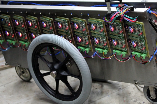
02.12.2014: Start construction of the upper pipeholder and the handles.
All performed using TIG welding. The vertical tubes are 50 mm x 2 mm x 480 mm
and 50 mm x 1.5 mm x 480 mm. The thin pipe was very difficult to weld.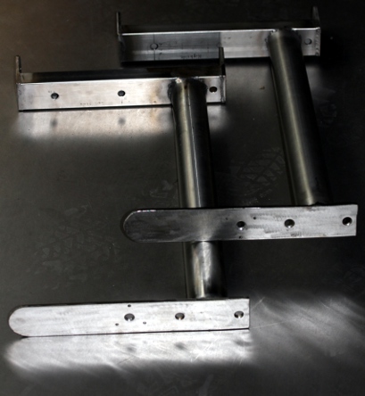 Construction and placement of the holder for the back row pipes. This is secured
with four M10 x 50 bolts.
Construction and placement of the holder for the back row pipes. This is secured
with four M10 x 50 bolts.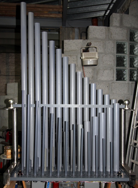
03.12.2014: Mounting of the pipeholder on the base assembly. The frontal connector
appears to have too short wires the reach the female. So, we extended the wires
that were too short. The robot is ready to receive firmware and... to play.
Kristof Lauwers is working on the patches in the Axoloti firmware. By accident
we drilled a hole in the mid-row connector. We will have to replace it... Connectors
ordered from Reichelt. Problems with uploading patches to the ARM boards...,
so sounding <Hybr> is on hold for a while. 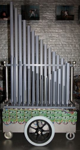 Decided
to change the two small gray wheels for pivoting wheels with green polyurethane
tires as we encountered problems with the steering. The building height of these
is 125 mm. Steering is perfect now.
Decided
to change the two small gray wheels for pivoting wheels with green polyurethane
tires as we encountered problems with the steering. The building height of these
is 125 mm. Steering is perfect now.  Connecting
bolts and nuts finalized and tightened. Name plate 'Me fecit godfried-willem
raes' mounted. Some ordered E14 fitting 12 V lights came in from Conrad.
We do not know as yet what colors to use here... green, tungsten or white?
Connecting
bolts and nuts finalized and tightened. Name plate 'Me fecit godfried-willem
raes' mounted. Some ordered E14 fitting 12 V lights came in from Conrad.
We do not know as yet what colors to use here... green, tungsten or white?
04.12.2014: Running out of argon gas, so no welding possible... Stuck on Axoloti
patch development... White LED strip added on the front bottom side, below
the ARM processor boards.
05.12.2014: Sawing and polishing of a large polycarbonate protective plate,
thickness 8 mm, for the front side of the robot. The standoff's on the
underside have M10 x 140 bolts and a 90 mm long distance holder made in thick
stainless steel. Still waiting for progress in the development of uploadable
patches on the ARM boards.
06.12.2014: Construction of protection plate finalized. First test of the midi
hub board. 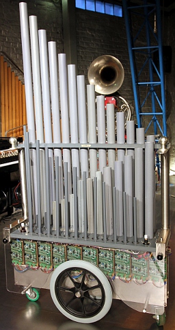 After correcting
a minor bug in our GMT testing software the lights as well as the muting circuit
(mapped on controller 66) do work to perfection. However as soon as we enable
the amplifiers, a 100 Hz hum becomes audible through all the speakers.
The rest current of the amplifiers without signal totals some 2 A (calculated
after the datasheet) and causes a voltage drop on the power supply voltage to
15.1 V. We measured the hum component on the power supply and indeed, it measures
some 200 mV. To damp this we could either use a filter circuit with a power
transistor, or an old passive solution: a third order butterworth low pass with
a hefty inductance ( 6.8 mH, 0.12 Ohm resistance, copper wire diameter 2.5 mm).
If we choose the -3dB cut off frequency at 1000 Hz, the damping at 100 Hz, a
decade lower, should be -60dB.
After correcting
a minor bug in our GMT testing software the lights as well as the muting circuit
(mapped on controller 66) do work to perfection. However as soon as we enable
the amplifiers, a 100 Hz hum becomes audible through all the speakers.
The rest current of the amplifiers without signal totals some 2 A (calculated
after the datasheet) and causes a voltage drop on the power supply voltage to
15.1 V. We measured the hum component on the power supply and indeed, it measures
some 200 mV. To damp this we could either use a filter circuit with a power
transistor, or an old passive solution: a third order butterworth low pass with
a hefty inductance ( 6.8 mH, 0.12 Ohm resistance, copper wire diameter 2.5 mm).
If we choose the -3dB cut off frequency at 1000 Hz, the damping at 100 Hz, a
decade lower, should be -60dB.
07.12.2014: Mounting the low pass filter on the chassis. We used a piece of
20 x20 x 3 stainless steel L-profile to mount the very large and heavy
self inductance on the bottom side of the backpanel. It can be taken out by
loosening the two M5 bolts. For the electrolytic capacitor at the output
we used a high quality 47000 uF/ 40 V Kemet type. The 12 V power connections
at the filter output are accessible for measurements from the outside. Measurement
of the hum component with this new filter gives a value of 3 mV, more than the
calculated and expected value of 0.2 mV but still a substantial improvement.
Any remaining hum must be due to ground loops, almost unavoidable in this design.
Obviously the pipes for notes 43 and 44, resonating at 98 and 103.8 Hz respectively
will amplify any residual 100 Hz hum, thus opposing the effectivity of our filter.
Measurement of the rest-current (with mute disabled, so controller 66 on): 2.15
A. Start cutting of a second polycarbonate protective plate for the backside.
This plate will be less deep than the front plate. Sizes: 1000 mm x 220 mm x
8 mm.
08.12.2014: Further work on Axoloti patches by Kristof Lauwers. It still seems
to be very shaky. Waiting for a working version of an uploader...
Finishing of back panel polycarbonate plate in the meanwhile. To mount it, we
had to replace the M10 x 70 cylinder bolts holding the pipeholder on the pipe
mounting plate with countersunk type M10 x 60, with countersinking into the
PVC plate. Otherwise it was impossible to mount the transparent backplate with
two M8 x 25 bolts. 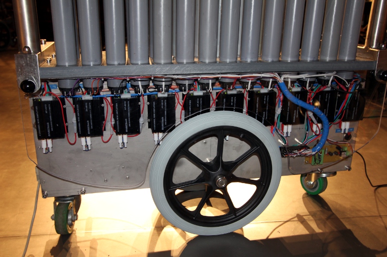 Testcode
in GMT completed for all controller and features implemented so far by Kristof..
Testcode
in GMT completed for all controller and features implemented so far by Kristof..
09.12.2014: We got <Hybr> as far as sounding two notes... 42 (F#) and
44 (G#), too soft for now but enough for evaluating the functionality of most
of the controllers. Checked: Ctrl #20, tuning (quartertone up or down, default
value 64), controller #1 (wind/randomness), #3,#4: tremolo, #5, #6: vibrato,
#7 global volume. The audio signal level from the ARM board, being 30mV only,
is too low to steer our amps. It needs to be at least a factor 10 (20 dB) higher.
It should be possible to reach a 0 dB (775mV) level, even taking into account
the 3.3 V ARM power voltage.
10.12.2014: Spare STA540 chips ordered from RS-components. Photoshoot with <Hybr>...
11.12.2014: Waiting for flash upload implementation under Axoloti from Johannes
Taelman...
12.12.2014: In testing one of the ARM processors, we discovered a wiring bug
in the Bulgin 33-pole connector for lowest rank of pipes. This is how the wiring
ought to be: We resoldered the plug connector corresponding to this wiring diagram.
13.12.2014: Output volume from the ARM board is now eight times higher.
Tests with the notes <Hybr> can produce so far...
15.12.2014: Firmware upload seems to work now, although it's still a bit shaky
and awkward on connecting as it requires two USB connectors for each board.
We got six notes playing so far... It is required to reboot the ARM boards after
an upgrade of the patches.
16.12.2014: All firmware uploaded now together with Kristof's patches. Six notes
seem to be shaky for some reason. Further debug required.
17.12.2014: A check of the voltages revealed a flaw in our design: the 5 V power
supply is clearly underdimensioned now, as with all ARM boards working, the
voltage sinks down to 3.5 V with shaky behavior for the midi signal levels as
a consequence. We will have to replace the 15 VA transformer for the 5 V power
supply with a 30 VA type. For test, we replaced the 5 V power supply by a Traco
SMPS module capable of delivering 6 A. Indeed, now it works... All notes on
Hybr do play now, but there will be still lots of fine tuning in the Axoloti
patches required. First preliminary presentation and demonstration of <Hybr>
under gesture control by the author at the occasion of the 'Snow' production
of the robot orchestra.
18.12.2014: Further work on test code in GMT and preparation of some 'real'
music sequences for evaluation. Although too late to be applied in <Hybr>,
we traced some types of very small diameter speakers that would have been suitable
-if not better- for sounding the notes 52-54 (Visaton type K40-50, 40 mm diameter),
notes 55-57 (Visaton K36WP-50, 36 mm diameter), notes 58-66 (Visaton K28WP-50)
and for notes 67 and up (Visaton K16-50, diameter 16 mm). They can be ordered
from Reichelt and appear in their latest catalogue on page 1319. If ever, we
would extend <Hybr>, we would certainly use these speaker types.
19.12.2014: The ordered female 30-pole connectors came in from Reichelt. Hybr
demo for Laura Maes.
20.12.2014: Research and measurement of the required volume scaling for intonation.
Global sound production measured at 1 m distance from the instrument. With 4
pipes sounding, we easily get to 93 dBA.
21.12.2014: Extensive testing under GMT, with velo-scale lookups. Sound pressure
level obtainable on a full cluster, with scaled velocities: 102 dBA. With proper
settings for the envelope controllers, <Hybr> is capable of producing
very percussive sounds.
22.12.2014: Hybr demonstration for Lara Van Wynsberghe, as it should participate
in the Dreigrosschenoper production next year.
24.12 2014: Calculation of the measured overtones in fractional midi units,
to comfort programming into the Axoloti patches. The appropriate columns were
added to the pipe description and measurement table above.
28.12.2014: Hybr integration in the orchestration for the Dreigrosschenoper,
by Lara Van Wynsberge.
03.01.2015: Hybr demonstrations for many friends. Very preliminary...
04.01.2015: Coding a Namuda study for Hybr...
05.01.2015: Further work on the Axoloti patches by Kristof Lauwers.
06.01.2015: The implementation of keypressure with a default value of 64 and
a bipolar range for tuning seems very awkward. We are encountering some problems
with the implementation of program change commands as well.
07-08.01.2015: New Axoloti patches uploaded in the ARM processors. Testing in
PD and GMT. The controllers for the strength of the inharmonic overtones seem
to lead to a crash condition on the ARM processors.
09.01.2015: Further fine tuning of the Axoloti patches by Kristof Lauwers. Conformation
of the crash condition with the overtone controllers. Possible causes: audio
buffer overflow, midi buffer overflow, too heavy load in the IRQ handlers, exceeding
the number of controllers supported in Axoloti? We have to find this out and
may have to contact Johannes Taelman for advice.
10.01.2015: Composition of the first Namuda Study for <Hybr> finished...
It can be performed by Dominica Eyckmans and Emilie De Vlam.
13.01.2015: Hybr survived its premiere. Here is a link
to a small picture album on the event.
19.01.2015: Further testing of crash conditions by Kristof Lauwers.
20.01.2015: Works on a treble extension for <Hybr> started: <HybrHi>
may come...
23.01.2015: Continued work on the velocity scaling in the Axoloti patches by
Kristof Lauwers.
07.02.2015: Stainless steel caps for the E14 light bulb sockets turned on the
lathe. 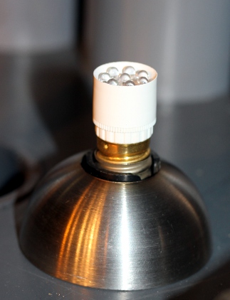 This element
is similar as what we did for <HybrHi>.
This element
is similar as what we did for <HybrHi>.
08.02.2015: Namuda coding 'Seduction' for Hybr in combination with the other
members of the robot orchestra. <Hybr> got a physical place in the orchestral
setup.
09.02.2015: <Hybr> made its debut on television in the 'Iedereen Beroemd'
series on VRT-TV1. The broadcast shows <Hybr> being programmed by Kristof
Lauwers.
21.04.2015: Xavier Verhelst finished his composition for <Hybr> and <HybrHi>.
30.09.2015: Apparently controller 66 off does not reset the pitch-bends on the
individual notes. This ought to be remedied in a next upgrade of the firmware
for both <Hybr> and <HybrHi>.
19.10.2015: Check-up of <Hybr> and <HybrHi>. They survived the concert
and the transportation to Dok19 very well.
25.10.2015: Fourier transform code tested with great success in Namuda Study
#57, Tekstuur.
09.06.2016: Hybr demonstration and explanation for Berlin composers for the
'Wir sind die Roboter festival'.
18.08.2016: Considering to make a real bass version of <Hybr>, Could become
<HybrLo>... if we only had the money.
19.09.2016: <HybrLo> is coming...
26.09.2016: <Hybr> and <HybrHi> transported to Berlin for participation
in the 'Wir sind die Roboter' Festival.
03.10.2016: <Hybr> checked on return from Berlin. Note 66 (F#) is not
working anymore. Repair required... Loudspeaker found to be fully burned out.
Replacement was not an easy untertaking, as the speaker was glued on the PVC
cone and in trying to remove it part of the conical foot broke. Thus we had
to make an ring with internal 50 mm diameter to fit over the broken part, maintaining
overall length. After all, quite an expensive repair as is took us 4 hours.
05.10.2016: Analysing the failure: If we recalculate the parameters again, we
have under worst case conditions 5.65 V rms output from the power amps (with
Uv=17V), leading to a power of only 638 mW to be dissipated in the 50 Ohm speaker.
This is way below the rated 2 W power for these speakers. So, the only explanation
for the burn out should be sought in exagerated cone excursion when sharp resonance
occurs in the pipes.
30.10.2016: Midi input connector broken because of very bad and utmost rough
treatment by Logos collaborators... <Hybr> was moved without first loosening
its wiring.
30.07.2017: Trouble with tuning. Procedures in g_mm.inc now setting ctrl. 124
according to the manual,
01.08.2017: <Hybr> on the road to Liepaja.
09.08.2017: <Hybr> returned from its trip to Liepaja, but the midi-input
socket was found to be fully molested.
10.08.2017: Repair session on the midi-hub board. Replacement of the Preh-din
connector. A tedious job, as the board is pretty awkward to disassemble, but
mission accomplished. New connector mounted.
07.09.2017: The fault with the midi-in connector on <Hybr> re-appeared.
Again someone must have moved Hybr without first removing its wires...
06.12.2017: Midi-hub board taken out again, DIN input resoldered and secured
with epoxy rosin. Here is a memo for the wiring of that board: 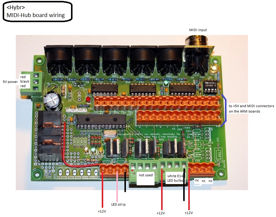
10.07.2018: <Hybr> plays an important role in our production of Erik
Satie's 'Relache'.
02-06.09.2019: <Hybr> on the road to Koeln for a WDR recording and compositions
by Sebastian Gramms.
04.06.2019: Failure reported by Lara Van Wynsberghe: Notes 57-60 do not work
anymore. The power line fuse to amplifier #7 was seated in a loose holder. Material
fatigue in the nylon we suppose. We simply bridged the fuseholder...
25.02.2020: As we could not solve the persistent bug with the tuning reset in
the ARM firmware, we found a solution by designing a 'booter' board capable
of cold resetting Hybr as well as HybrHi. Here is the circuit diagram: 
26.02.2020: PCB designed for the booter-board.  5V
relays ordered from Farnell. (Omron G4A1APE5DC). Etching, drilling and soldering
of the PCB.
5V
relays ordered from Farnell. (Omron G4A1APE5DC). Etching, drilling and soldering
of the PCB. 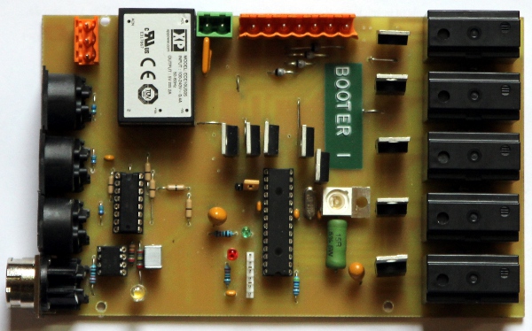
27.02.2020: Firmware for the <Booter> is up and running. Version 1.0.
01.03.2020: Further documentation on the booter device
is available on its own page.
14.09.2023: <hybr> transported to Deutsche Oper Berlin for the Zeroth
Law production.
02.10.2023: <Hybr> returned safely from its performances and transportation
from and to Berlin.
31.10.2023: Oscillation observed on the 5V power supply... Failure of the Traco
5V/6A module?
02.11.2023: Traco TML30105 failure confirmed: under load conditions, if not
hicking up, it outputs only 4.2V. Under no load, the output is 6.8V. It is getting
very hot and emits a phenol smell. The fully encapsulated module cannot be repaired
and needs replacement. It would be good to go for a somewhat more powerfull
type: 5V / 10A should do. Order placed at Farnell. This is the new circuit:
03.11.2023: 5V power supply replaced. Now a PSK-60-5-T type (Farnell order nr.,
359-4870) However, on booting, the same problems returns: the power hickups...
Output voltage sinks to 4.2V... If we remove the 5V line to the external audio-input
board, the problems seem to disappear... To be analysed.
04.10.2025: <Hybr> and <HybrHi> join the palaver party at Flagey
for Brussels Philharmonic. Animators are Hans Roels and Mattias Parent.
05.10.2025: <Hybr> returned from the palaver production in Brussels, Flagey.
One of the green polyurethane wheels (Blickle) ruined through aging. The polyurethane
found to be disintegrating. We replaced the wheel, but unfortunalety the replacement
is just as old as the one found deteriorated. As <Hybr> was transported
flat, we found the central axle displaced. This had to be done, but we need
a couple of helping hands to do this...
TO DO:
Replacement of the broken mid-row female connector
Further development and debugging of patches on the Axoloti platform. Tasklist:
Thorough testing of the analog input functions.
Implementation of lead battery operation.
Construction of a suitable flightcase.
Testing and evaluation with the definitive firmware.
Maintenance information:
Circuit diagrams:
ARM-boards and audio amplifiers:
Power supply circuits:
The 6.8 mH self inductance is made by InterTechnik Gmbh, type FE130, its intended
application being loudspeaker cross over filters. These coils have an open E
core and are wound with 2.5 mm diameter copper wire.
Midihub board:
Wired board:
Firmware for the PIC microprocessor on
this board.
Hex-dump of the assembled code
Audio input circuit with low pass filter:
Prototype board:
Hybr & HybrHi booter board (2020):
by Godfried-Willem Raes
Further reading on this topic (some in Dutch):
Audsley, George Ashdown 'The Art of Organ-Building', ed. Dover Inc, NY,1965,
(first edition: 1905) ISBN 0-486-21314-5
D'Appolito, J. 'Luidspreker-meettechniek', ed. Segment BV, Beek , Nederland,
2000, ISBN: 90 5381 116 8
De Keyser, Ignace 'Challenging
von Hornbostel & Sachs' , 2019
Raes, Godfried-Willem , Expression
control in musical automates
Raes, Godfried-Willem, HybrHi
Raes, Godfried-Willem, HybrLo
Raes, Godfried-Willem, 'Logos @ 50, het kloppend hart van de avantgarde muziek
in Vlaanderen', ed. Stichting Kunstboek, Oostkamp, 2018. ISBN 978-90-5856-605-8
Taelman, Johannes 'AXO development platform' (Hasselt, 2014)
Maintenance and disassembly instructions:
Before undertaking any repair on this robot we strongly advise to
first read through our construction diary, as this will clarify fully
how the machine was originally designed and assembled.
To upgrade the firmware in the ARM-processors, or to repair any boards on the
front side the transparent protective cover should be removed.
For repairs, exchanging fuses and adjustments on the BaseTech
amplifiers on the backside, similarly, the backplate should be removed.
If for any reason, the 12 V DC voltage would fail, the most likely
cause is either a blown fuse or the position of the green switch on the
black box containing the toroidal transformer. To access any
circuitry sandwiched between both bottom plates, remove the upper
pipeholder first. Make sure to disconnect the two 30-pole connectors as well as the Bulgin 36-pole connector on the back.
Removal of the midihub board, holding the 18F2525 processor is possible without removing any bolts other than the M3 bolts wherewith the board is mounted on the side panel. First remove all Weidmueller connectors from the board and make sure to note the place where they should go back before loosening any of these connectors.
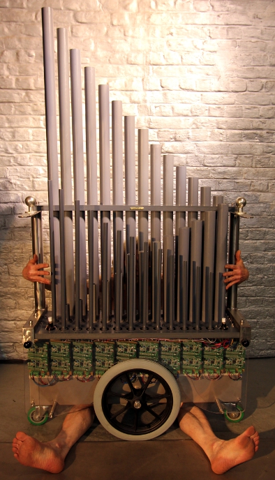
Robody picture with <Hybr>:
[EOF]