<Balsi>: Large motor
driven siren
The instructions in the score render it impossible to
use a standard crank driven siren, as it is detrimental to the gears in
these devices to be started and stopped fast. So an electrically driven
mechanical siren with safe braking possibilities or fast sound control
has to be designed. The score is very unclear as to the pitches the sirens
are supposed to sound. In the score they appear notated as percussion
instruments. We made already a few siren driven robots: <Sire>
, a robot using 24 small sirens as well as the large siren integrated
in <Springers>.
The documentation for <Balsi> is
on a separate webpage. Click here.

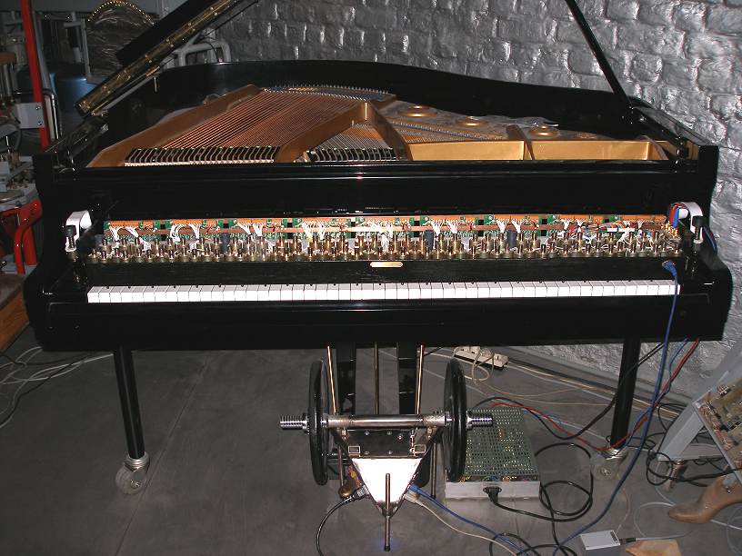
Player Pianos:
The original score requires 16 player piano's, although there are only
four autonomous tracks. The reason behind this, is that on traditional
piano rolls, it is impossible to have that amount of notes as the paper
would fall into pieces. Obviously electrically driven automated pianos
do not have this restriction making performances using just 4 player pianos
perfectly possible. All performances so far if using player pianos (and
not sample-based midi keyboards with their uggly sound...) at all, suffered
from the problems associated with commercially available midi controlled
pianos: latency (500ms), lack of polyphony, weak dynamic possibilities.
This is the case for the Yamaha Disklavier, the Q&R vorsetzers etc...
The player pianos as we designed and build do not have any of these problems.
Detailed descriptions and comments on our Player
Piano's can be found on this website. The only problem is that at
the time of this writing (2015) we made only two copies. So either we
have to make two more vorsetzers, or rearrange the score to get it played
on the two pianos we already have.
Musicians parts:
The score calls furthermore for three xylophones, two grand pianos, a
tamtam, four bass drums. It is perfectly possible to also confine these
parts to real musical robots. Our <Xy>
robot can take care of the xylophone parts. Automating the bass drums
and a tamtam would be pretty straightforward...
Midi Implementation for all components of <Balmec>
The Balmec project was conceived to work like all other musical robots
we have built. Hence it makes use of one unique midi-channel and all components
of the project are mapped on midi notes and controllers.
Midi channel: 13 (counting from 0) for all modules.
Note On/Off mapping:
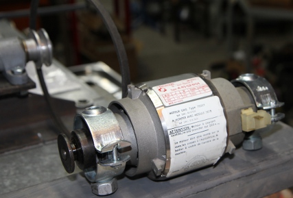
Note 24: Siren. The maximum speed is controlled by controller #24. Note-On
commands let the siren speak freely, Note-Off commands mute the siren.
To stop the siren motor, controller 24 must be set to zero.
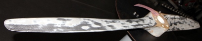
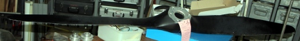
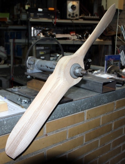
Note 36: propeller 3 (large metal propeller). The speed of rotation is
controlled by the velocity byte
Note 38: propeller 2 (large wood propeller). The speed of rotation is
controlled by the velocity byte
Note 40: propeller 1 (small propeller). The speed of rotation is controlled
by the velocity byte
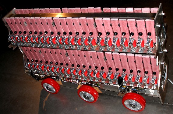
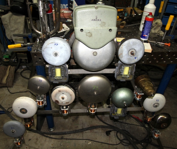
Notes 51 - 93: Electric bells on <Bello>. The velocity byte
steers the loudness (the force of the stroke) and repetition rate can
be controlled with the key pressure command. The repetition speed set
with the key pressure command is 'sticky', so users do not have to send
it again for every note. The key pressure command can also be sent when
no notes are playing. If the repetition rates are set high, low velocity
values ought to be used.
Note 119: switch on/off the red LED bottom lights on <Bello>. The
velocity steers the brightness of the light.
Notes 120 and 121 switch on/off the red LED spotlights on propeller 1.
The velocity steers the speed of the flashing. Keypressure can be used
to further modulate the flashing speed.
Notes 122 and 123 switch on/off the red LED spotlights on propeller 2.
The velocity steers the speed of the flashing. Keypressure can be used
to further modulate the flashing speed.
Notes 124 and 125 switch on/off the red LED spotlights on propeller 3.
The velocity steers the speed of the flashing. Keypressure can be used
to further modulate the flashing speed.
Notes 126 and 127 switch on/off the red LED spotlights on <Bello>.
The velocity steers the speed of the flashing. Keypressure can be used
to further modulate the flashing speed.
Controller 66: Switches off all components when the data byte is zero.
If a non-zero value is sent, the components are powered on. Controller
66 with value zero also resets all controllers to their default startup
values.It also resets the note-repetion rates on <Bello>.
Controller 123: All notes off, without affecting any controllers nor
key-pressure settings.
Prof.dr.Godfried-Willem Raes
Collaborators on this project:

 This
is the circuit for the control:
This
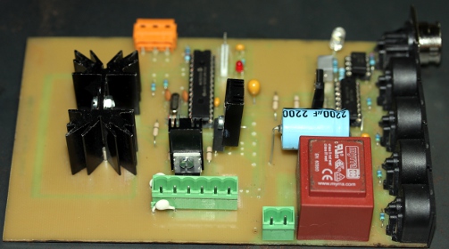
is the circuit for the control: And, this
the PCB for the above circuit.
And, this
the PCB for the above circuit. As we did not find enough space on the board to accomodate a 2.2mF / 450V
electrolytic as originally foreseen in the schematic, we mounted a 470uF/400V
type. If a larger value is required it will have to be added off-board.
The motor brake relay as well as the braking resistor (or light bulb)
should be mounted on the motor itself. As parts of the PCB are directly
coupled to the mains voltage a word of warning may not be misplaced here:
this board does carry high voltages! Do not touch. There is galvanic isolation
between input and output, so using the circuit involves no danger. The
steel structure itself is properly grounded.There are two automatic fuses
on the machine making it possible to cut all power, however these fuses
should not be used as a switch taking into account that being in such
close proximity to the propeller entails a danger in its own, For safety
reasons we advise users to use a switch in the power wire at least 5 meters
away from the engine.
As we did not find enough space on the board to accomodate a 2.2mF / 450V
electrolytic as originally foreseen in the schematic, we mounted a 470uF/400V
type. If a larger value is required it will have to be added off-board.
The motor brake relay as well as the braking resistor (or light bulb)
should be mounted on the motor itself. As parts of the PCB are directly
coupled to the mains voltage a word of warning may not be misplaced here:
this board does carry high voltages! Do not touch. There is galvanic isolation
between input and output, so using the circuit involves no danger. The
steel structure itself is properly grounded.There are two automatic fuses
on the machine making it possible to cut all power, however these fuses
should not be used as a switch taking into account that being in such
close proximity to the propeller entails a danger in its own, For safety
reasons we advise users to use a switch in the power wire at least 5 meters
away from the engine. 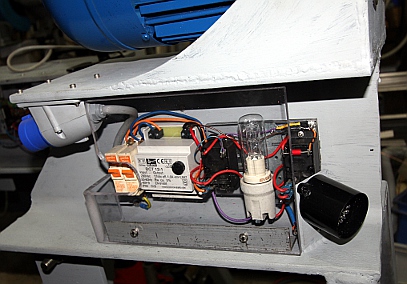
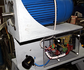

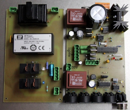
 The power
relays, the fuse holder and the SMPS 12V power supply found a place on
another printed circuit board:
The power
relays, the fuse holder and the SMPS 12V power supply found a place on
another printed circuit board: 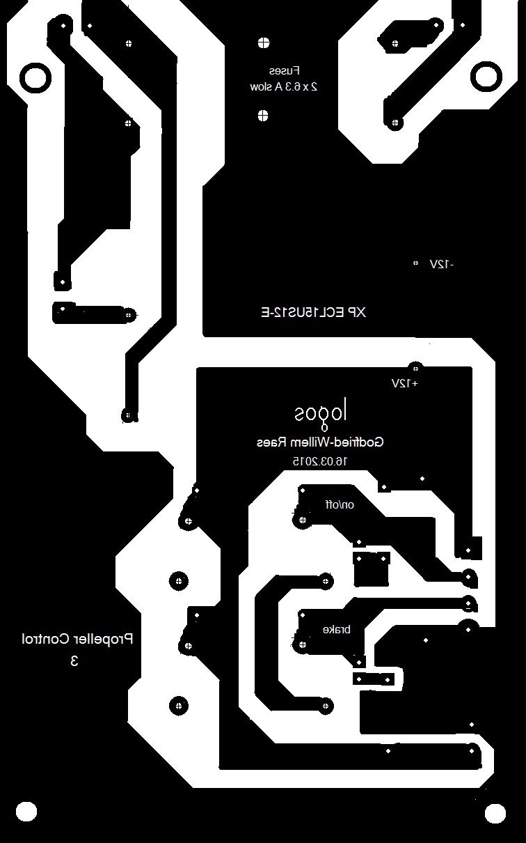 Making this board made final wiring a lot more transparant than was the
case for propeller 2.
Making this board made final wiring a lot more transparant than was the
case for propeller 2.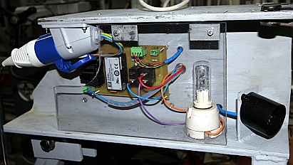
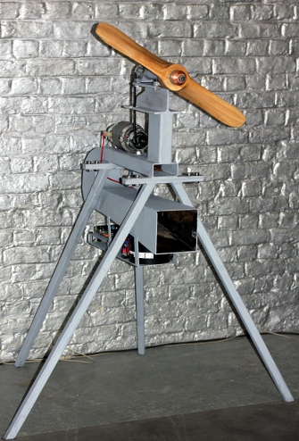
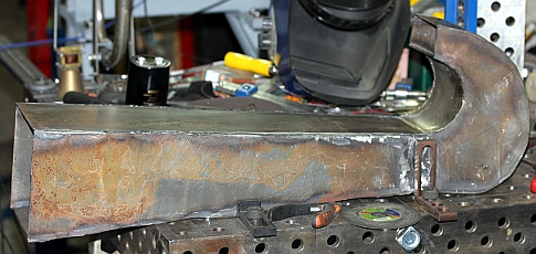
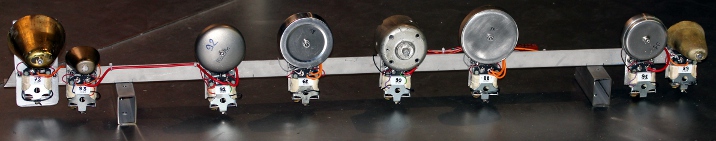
 We
leave the hole in the 100 x 50 profile open on purpose, as it may help
to produce an airplane sound. Decided to make the entire assembly with
propellers and bells like any other of our musical robots: midi controlled.
The advantage being that we do not have to design a user interface nor
control panel and that remote control using just about any commercialy
available midi controller by a single musician becomes possible. For safety
reasons alone, remote control seems mandatory in this project.
We
leave the hole in the 100 x 50 profile open on purpose, as it may help
to produce an airplane sound. Decided to make the entire assembly with
propellers and bells like any other of our musical robots: midi controlled.
The advantage being that we do not have to design a user interface nor
control panel and that remote control using just about any commercialy
available midi controller by a single musician becomes possible. For safety
reasons alone, remote control seems mandatory in this project.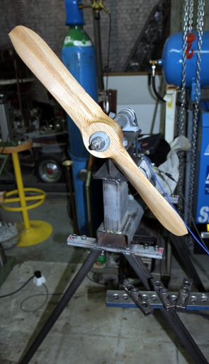 The
power supply should not exceed 100V at 5A. Current limiting should be
designed in.
The
power supply should not exceed 100V at 5A. Current limiting should be
designed in.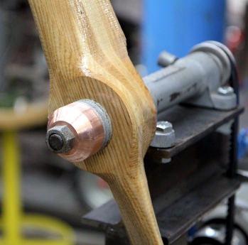 Test runs
with higher voltages up to 120V. The resonator tube works as predicted.
It could be made longer and we could make a bell for it. Sound level produced
now at 80V is 84dBA.
Test runs
with higher voltages up to 120V. The resonator tube works as predicted.
It could be made longer and we could make a bell for it. Sound level produced
now at 80V is 84dBA. The 500 VA transformer as well as the high voltage electrolytics came
in from Farnell. Thus we can go on with the construction of the power
supply. This is the circuit drawing:
The 500 VA transformer as well as the high voltage electrolytics came
in from Farnell. Thus we can go on with the construction of the power
supply. This is the circuit drawing: 

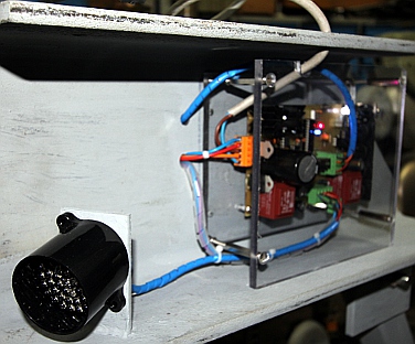
 And here is a first view on the assembly so far...
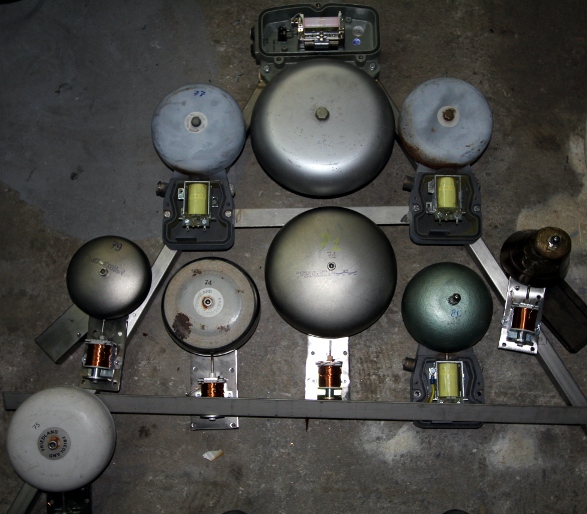
 Visiting the Funke and Huster site, we found out they also have bell shells
with 250 mm diameter. Chances are we can tune these to our missing pitches...
Let's inquire... (www.fhf.de). Also found some large shell (10",
or 250 mm) fire alarm bells on Alibaba.com, in China. We ordered two of
them... wait and see, or better, hear.
Visiting the Funke and Huster site, we found out they also have bell shells
with 250 mm diameter. Chances are we can tune these to our missing pitches...
Let's inquire... (www.fhf.de). Also found some large shell (10",
or 250 mm) fire alarm bells on Alibaba.com, in China. We ordered two of
them... wait and see, or better, hear.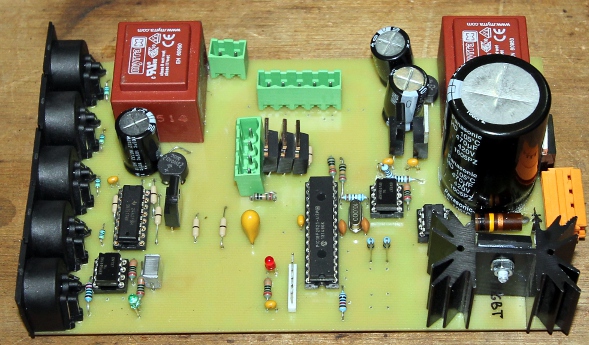

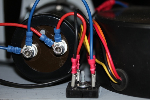
 When
the 12V supply voltage is off, both relays will be off. It looks like
a good solution for the braking circuit on the propeller motors.
When
the 12V supply voltage is off, both relays will be off. It looks like
a good solution for the braking circuit on the propeller motors.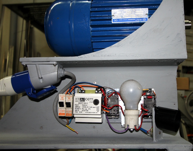 We choose an Osram 205 W halogen bulb (not seen on the picture) with a
cold resistance of some 25 Ohms. It is normal by design that this lamp
will never lite up. (It would in fact, if the motor were driven externally
by another motor...). If we had the mounting flange for the propeller,
the robot would be finished now...
We choose an Osram 205 W halogen bulb (not seen on the picture) with a
cold resistance of some 25 Ohms. It is normal by design that this lamp
will never lite up. (It would in fact, if the motor were driven externally
by another motor...). If we had the mounting flange for the propeller,
the robot would be finished now...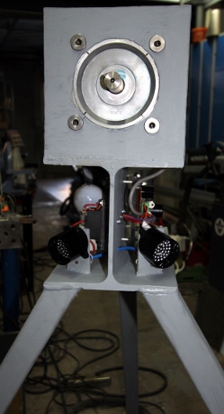
 Also
today two ordered bells came flowing in from China:
Also
today two ordered bells came flowing in from China:  These bells have 250 mm diameter. They are designed to work on 110V ac
current.
These bells have 250 mm diameter. They are designed to work on 110V ac
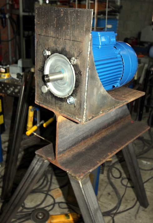
current.  Arc
welding of the tripod for propeller 3. The halogen bulbs (205W) came in
from Conrad as well as a bunch of Weidmueller connectors from Farnell.
Arc
welding of the tripod for propeller 3. The halogen bulbs (205W) came in
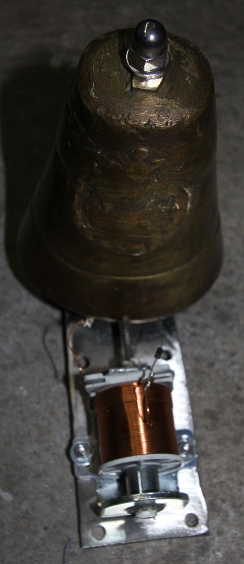
from Conrad as well as a bunch of Weidmueller connectors from Farnell.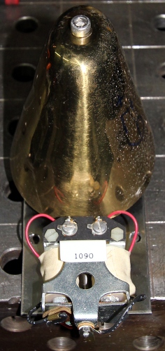 And this one sounds note 65:
 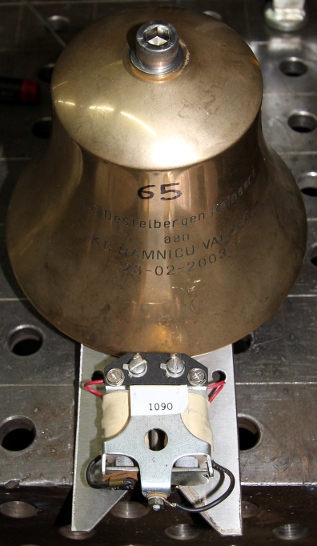 These two bells use a 24V mechanism.
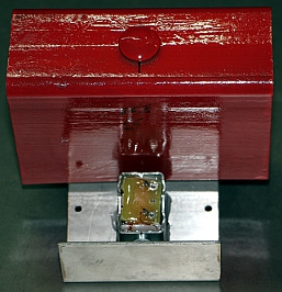
 Start
construction of the bottom plate (10 mm thick stainless steel plate 1310
mm long, 100 mm wide): drilling of mounting holes for the side wheels,
construction of an axle holder for the front and back wheels, drilling
of mounting holes for the power supply transformers.
Start
construction of the bottom plate (10 mm thick stainless steel plate 1310
mm long, 100 mm wide): drilling of mounting holes for the side wheels,
construction of an axle holder for the front and back wheels, drilling
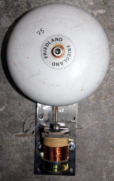
of mounting holes for the power supply transformers. and
82 (a Friedland coil). We have to search of a cause... Also the chinese
bells (notes 57 and 60) refused service. We took them apart for close
inspection and discovered that under the insulating PVC tape covering
one of the coils, a diode was hidden. Also close inspection revealed a
Chinese trick here: the bells are sold to operate on 110V ac, but their
coils are not a pair: one coil measures 248 Ohms and the other coil only
12.6 Ohms... So clearly with a minor wiring change they can sell one and
the same bell for 110V ac and for 6V to 12Vac... The weakness of the construction
though is that the coils giving very unbalanced forces, cause a lot of
unwanted mechanical noise... Bell 81 was not working, due to a typing
error in the firmware. We started making a worksheet in order to figure
out the optimum velocity scalings for the different bells.
and
82 (a Friedland coil). We have to search of a cause... Also the chinese
bells (notes 57 and 60) refused service. We took them apart for close
inspection and discovered that under the insulating PVC tape covering
one of the coils, a diode was hidden. Also close inspection revealed a
Chinese trick here: the bells are sold to operate on 110V ac, but their
coils are not a pair: one coil measures 248 Ohms and the other coil only
12.6 Ohms... So clearly with a minor wiring change they can sell one and
the same bell for 110V ac and for 6V to 12Vac... The weakness of the construction
though is that the coils giving very unbalanced forces, cause a lot of
unwanted mechanical noise... Bell 81 was not working, due to a typing
error in the firmware. We started making a worksheet in order to figure
out the optimum velocity scalings for the different bells.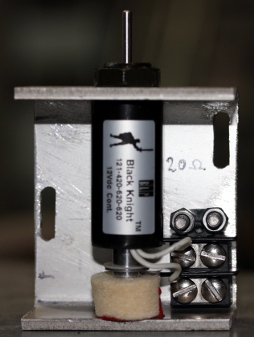 Wiring
redone as the existing wire was molten completely. Everything repaired
by the end of the day. Suitable brass dome found for note 72. Mechanism
constructed, using a 24V coil set.
Wiring
redone as the existing wire was molten completely. Everything repaired
by the end of the day. Suitable brass dome found for note 72. Mechanism
constructed, using a 24V coil set.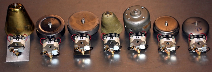 A full day of work...
And this be nr.8:
A full day of work...
And this be nr.8: 
 The
mechanisms for bells 90 to 93 were modified to work on 12V by connecting
the two coils in parallel. This brings the resistance down to 8.8 Ohm
and the peak current to 1.4A at 12 V. As the duty cycle will allways be
lower than 50% the maximum average current will be 0.7A. Bottom LED light
mounted and mapped on note 120. This can be PWM controlled with the velocity
byte. Bottom row assembly finished and mounted. All firmware adapted and
uploaded to the extra bells. The bottom row can be taken out of the robot,
therefore we used a 12-pole connector.
The
mechanisms for bells 90 to 93 were modified to work on 12V by connecting
the two coils in parallel. This brings the resistance down to 8.8 Ohm
and the peak current to 1.4A at 12 V. As the duty cycle will allways be
lower than 50% the maximum average current will be 0.7A. Bottom LED light
mounted and mapped on note 120. This can be PWM controlled with the velocity
byte. Bottom row assembly finished and mounted. All firmware adapted and
uploaded to the extra bells. The bottom row can be taken out of the robot,
therefore we used a 12-pole connector.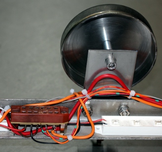 It connects to the main chassis with 4 M6 bolts and nuts. Pulse board
3 now services only 12 V loads. On board 2 we still have two free outputs:
P2.3 and P2.4. This as far as we are now:
It connects to the main chassis with 4 M6 bolts and nuts. Pulse board
3 now services only 12 V loads. On board 2 we still have two free outputs:
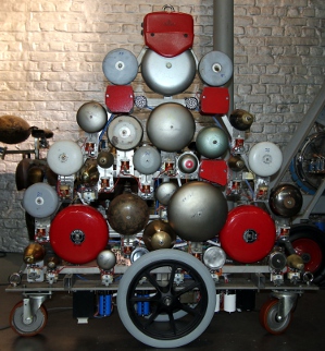
P2.3 and P2.4. This as far as we are now: 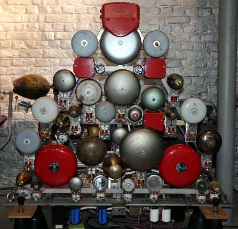 The wheels are still missing...
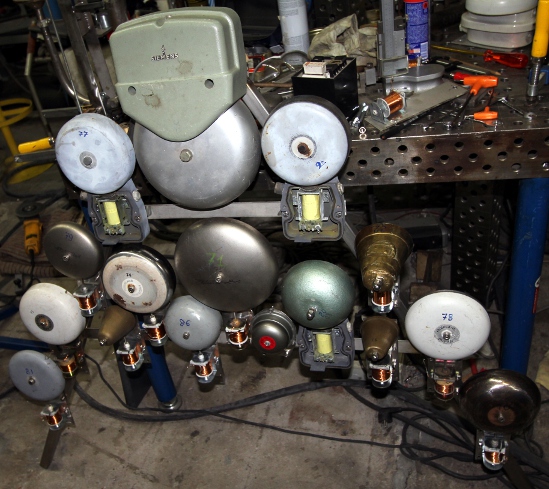
 Demonstration
for Ictus. First testing with the Antheil score material. This is what
it looks like now, nearly finished:
Demonstration
for Ictus. First testing with the Antheil score material. This is what
it looks like now, nearly finished:  And this is what the PCB looks like:
  Hopefully we have the time to etch and solder this before the Antheil
piece goes into production... this weekend. In fact it would be a good
idea to provide some place on the PCB for a simple SMPS 12V power supply,
as this would allow us to mount two red LED spotlights on this propeller
as well...
Hopefully we have the time to etch and solder this before the Antheil
piece goes into production... this weekend. In fact it would be a good
idea to provide some place on the PCB for a simple SMPS 12V power supply,
as this would allow us to mount two red LED spotlights on this propeller
as well...
 This bell is mounted
on the backside of the robot.
This bell is mounted
on the backside of the robot.