|
<Balsi> |
 |
|
motor driven sirens and alarms robot for Ballet Mecanique , George
Antheil by Godfried-Willem Raes 2014-2019 |
|
<Balsi> |
|
|
|
motor driven sirens and alarms robot for Ballet Mecanique , George
Antheil by Godfried-Willem Raes 2014-2019 |
<Balsi>: Large motor driven siren robot with volume control and extensions
The instructions in Antheil's score for Ballet Mechanique render it impossible to use a standard crank driven siren, as it is detrimental to the gears in these devices to be started and stopped fast. So an electrically driven mechanical siren with either safe braking possibilities or fast sound-muting control has to be designed. The score is very unclear as to the pitches the sirens are supposed to sound. In the score they appear notated as non-pitched percussion instruments.
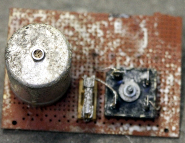
The siren we used as a starting point for this automation project, before we changed its mechanical construction, looked like this:
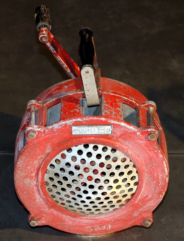
It is a heavy Polish made military siren we acquired on the local flea market in Ghent. The handgrip and the crank were removed first. The mount for the handgrip was modified to accomodate a bidirectional solenoid to drive a damper mechanism. Brand details are on the label:
Of course, from a mechanical point of view, driving the sound producing rotator of the siren directly with a motor would seem the easiest solution. After all, this is how electrically driven sirens generally work. However, starting from an existing and historical crank driven siren, this would require an almost complete redesign and balancing of the instrument as we would have to remove the system of dented wheels inside. If we estimate the maximum speed of rotation on the crank as 3 rotations per second, and if we choose a standard motor with 2750 RPM - that is ca. 46 rotations per second, we need belts or gears with a speed down proportion of ca. 1:15. So, if we take a small V-belt wheel on the motor, diameter 40 mm, the driven wheel needs to have 600 mm in diameter. That's way larger than whats readily available on the market... Moreover, frictional losses would become quite large. So, a two step gear, two times 1:4, looked like a better design at first...
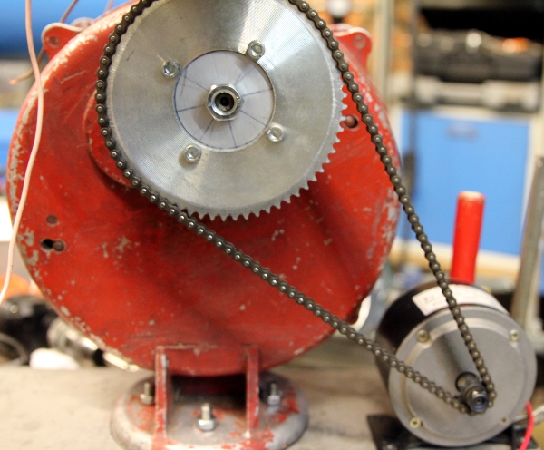
Before we tackled this project, we made already a few siren driven robots: <Sire> , a robot using 24 small sirens as well as the large siren integrated in <Springers>. In these earlier projects, we used DC motors and PWM control to drive the sirens. There was no reliable way to control the produced pitch precisely though. After many unsuccesfull experiments with gears and AC motors to drive this new siren, we came across a motor from an electric scooter. This motor had a dented wheel and drove the backwheel of the scooter with a chain. It looked like a perfect solution to the problem at hand here. Here is a detail of the chain solution as set up for the experiment:First failing approaches: (2017)
For <Balsi> we first decided to give a throw at using a regular AC 3-phase induction motor. Next to the fact that such motors are readily available at low prices, we took profit of the availability of 16-bit Microchip controllers specifically designed for applications in 3-phase motor controllers, type nr. 24EP128MC202 being our favorite for the time being.
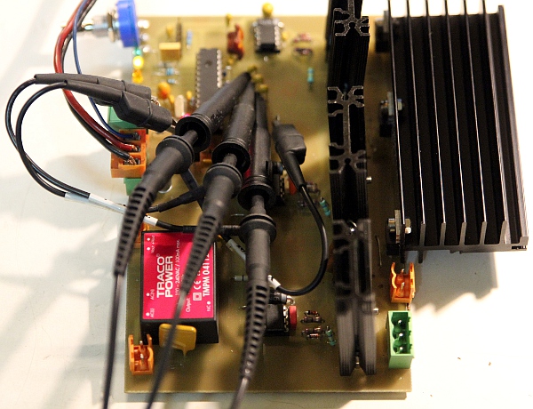
The circuit as we designed it looks like:
The PWM base frequency was taken as 20 to 25 kHz and is used to generate 3 sine waves with the required phase shift of 120 degrees.Control range for the speed of rotation is 150 to 3000 rpm. The filtering components on the MIDI input appeared to be essential, as the amount of glitches produced by the fast switching MOSFETS at high frequencies and voltage are considerable and caused erroneous and missing data. This is what the signals look like, as measured op the testpoints tp1, tp2 and tp3:
This was the setup for the test:
The motor control firmware builds on a pretty straightforward PID regulating loop. Here is the algorithm, coded in Power Basic:
FUNCTION PID (BYVAL sollvalue AS SINGLE, BYVAL seinvalue AS SINGLE, BYVAL OPT kp AS SINGLE, BYVAL OPT ki AS SINGLE, BYVAL OPT kd AS SINGLE) EXPORT AS SINGLE
' The machine constants have to be passed on the first call only. Seinvalue is the measured reality value, generaly derived from a sample. Sollvalue is the goal we want to achieve. The function returns the correction factor for regulation and should be used in a regulation loop. All parameters and in- and output values are normalized.
STATIC propconstant, integrationconstant, differenciationconstant AS SINGLE
STATIC oldfout, iterm AS SINGLE
LOCAL fout, pterm, dterm AS SINGLE
IF kp THEN propconstant = kp
IF ki THEN
IF ki <> integrationconstant THEN RESET iterm ' reset!
integrationconstant = ki
END IF
IF kd THEN
IF kd <> differenciationconstant THEN RESET oldfout ' reset differenciationconstant = kd
END
fout = sollvalue - seinvalue ' calculate the error
pterm = propconstant * fout. 'Proportionality term
iterm = iterm + (integrationconstant * fout). 'Integration term
dterm = differenciationconstant * (fout - oldfout)
oldfout = fout
FUNCTION = pterm + iterm + dterm ' return value for the PID correction signal
END FUNCTION
Although the software worked pretty well, unsurmountable problems plagued us with the motor driving components. Neither high voltage MOSFET's nor IGBT's survived our experiments. We started realizing that the design of a decent high voltage ac-motor controller is more involved than what can be found in the many textbooks and application notes on the subject. Looking into available designs by Siemens, Lust, Hitachi, ABB, we noticed they had about tenfold as many components as our designs. Taking into account that these drives sell for 150 to 300 Euro's, it just appeared vain to undertake a new design. We performed many experiments with these industrial controllers, but finally we abandoned them for the speed resolution appeared limited to maximum 10 bits, not enough to control the pitch on our siren with the required 16-bit precision.
Second and now working approach: (2018-2019)
As we never got our motor controller circuit to operate properly and reliably on the high voltages involved, we abandoned the first design. As an alternative, we changed for a DC motor taken from an electric scooter. These motors work on a nominal 24V and deliver a power of 350W. These motors also are characterized for a pretty high starting torque. To drive the siren, we used a chain and chainwheels, recycled from the scooter. As the current drawn is quite high (16A according to the motor shield plate), we decided to use optocouplers in the motor controller.
A novel component in this design is the addition of a damper mechanism. An often inconvenient property of sirens in music, is that the sound volume is always proportional to the pitch produced. To overcome this inconvenience to a great extend, we made a damper consisting of a circular plate that can cover the suction side of the siren. The plate is driven by a bidirectional solenoid, mounted in top of the siren. The construction is shown in the picture:
Experiments with the siren running and the damper quickly made us encounter some problems: as the speed of the siren goes up, the suction force excerted on the damper plate rises considerably. To such an extend even, that the solenoid is not strong enough the open the damper anymore. Thus it became mandatory to use the solenoid on an overdriven voltage and to provide the firmware with some intelligence to make the solenoid force a function of the siren speed. Another effect we noticed, is that the pitch of the siren becomes a function of the damper position. With the damper closed, and the siren driven with a same voltage, the pitch can be up the a fourth higher. To make precise control of the produced pitches possible, we added a tacho circuit, using the classic LM2907 chip. Here the chip is used in a non-standard frequency doubling configuration. The output pulses are fed to an external interrupt input on the microprocessor for period calculation. A PID regulator was to be implemented in the firmware.
As we had another smaller motor driven siren on our shelves, we decided to add this one to the project as well. This siren appeared to be driven by a 230V universal motor. Thus, a candidate to be driven with DC under PWM control. As this addition required another set of PWM controls, we designed a second board, adding a rotating police flashlight at the same time. The circuit is very similar, except for the universal motor drive.
The overview of the required circuits now became:
The circuit for the midi-hub board, also housing the 5V power supply for the pic microcontrollers looks like:
The PCB for this circuit is almost identical to the board we made for the <HybrLo> robot. In the firmware, a midi-parser is implemented as well, such that the midi TTL outputs carry only information relevant for the boards connected. The 1 ms delay caused by the parser is of no practical musical consequence as at is neglectible compared to the inherent slugishness of the siren itself. Here is a picture of the finished hub-board:
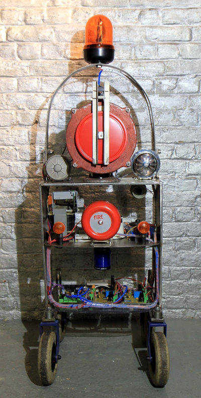
During the design and construction process we decided to add a few more automated components in this <Balsi> robot, to make a more universally useable machine. Thus we added two smaller motor driven sirens. One of them is a universal motor driven siren, still quite loud but way softer than the large siren. The range for this siren is a lot higher than what can be reached with the large siren. The third siren is a 24V DC motor driven siren, capable of reaching 1600Hz. Also we found place to add four car horns and a motor driven electric fire alarm bell. For the large siren, we implemented very precise pitch controll using PID regulation and a sensor. Some visual components were added as well: two rotating flashlights, one orange, one blue and two orange pinker lights recycled from a motor bike.
The firmware for the three microprocessor boards, written in Proton Basic (as of 2022, Positron Basic) , can be downloaded here:
- Hub board firmware, with midi-parser code
- Motor board 1 : large siren and damper mechanism
- Motor board 2: small sirens and rotating lights
Midi implementation:
Note on/off:
Note 24: Siren 2 :small siren. The velocity byte steers the 7-bit MSB of the pitch, corresponding to the midi note. (Controller 24 can be used to steer the LSB with cents resolution), Noteoff switches the siren off and resets controller #24. The range for the LSB is more or less a semitone. Acceptable values for the velo byte are between 54 and 89. The minimum value for the velocity bit is 42, but at that motor speed the sound is barely audible. The value of the velo byte corresponds more or less with the midi note the siren will sound. Due to frictional losses in the sirens well as temperature changes, the pitch may be a quartertone up or down. More precise tuning can be achieved after the note on command by using controller #24.
Note 25: Siren 3: small siren. The velocity byte steers the 7-bit MSB of the pitch, corresponding to the midi note. (Controller 25 can be used to steer the LSB, with cents resolution), Noteoff switches the siren off and resets controller #25. The range for the velo byte is between 56 and 83. Values as low as 44 will be accepted, but are bare audible notes.
Note 28: bell. The velocity byte steers the speed of rotation. It's a motor driven bell and thus the volume is a function of the velo byte. The motor starts running from velocity values 27 on. Witk value 127 the bell sounds as loud as it can.
Notes 29 to 86: Switches the large siren on and sets the pitch to the requested note. Due to the large inertia of the rotor, reaching the requested pitch allways needs some time. Sending consecutive scales to the siren makes no sense. If up and down going glissando is required, just send the ending note and the beginning note of the required span. Note-off commands with a release value can be used to steer the action of the damper at the end of a note. With a high value, the damper will stay open and no damping will occur. With a zero value, damping will be at maximum.
Note 96: horn 1, on/off only, Key pressure implemented for note repeats. Pitch = midi note 68 (G#4)
Note 97: horn 2, on/off only. Key pressure implemented for note repeats. Pitch = midinote 69 (A4)
Note 98: horn 3, motorbike claxon . Pitch = midi note 63 (Eb4)
Note 99: horn4, Wersi claxon with horn. Pitch = midi note 66 (F#4)
Notes 120: Orange rotating light. 120 steers the light, controller 120 steers the rotation speed. The value for controller 120 stays in effect and does not have to be resent on each subsequent note-on command. De default startup and reset value voor this controller is 64. Note off for the light allways stops the motor.
Note 122: Blue police LED rotating light. On/Off only.
Note 123: Orange light, left side. On/Off. Flashing speed controlled by the velocity byte.
Note 124: Orange light, right side. Flashing speed controlled by the velocity byte.
Controllers:
#7: Volume controller for the damper on the large siren. Default value = 64
#24: sets the LSB for the pitch of the small siren. The controller should be sent after the note-on command. Default value = 0. One unit corresponds to 1 cent, so the range is 0 to 127 cents.
#25: sets the LSB for the pitch of the 3th siren. The controller should be sent after the note-on command. Default value = 0. One unit corresponds to 1 cent, so the range is 0 to 127 cents.
#48: sets the LSB for the pitch of the large siren. The controller should be sent after the note-on command for any note within the range. Default value = 0.
#66: power on/off. Power off resets all controllers to their default cold boot values. Default value = 0
#67: large siren PID pitch regulation ON/OFF switch. Default value = 0.
#68: lock-in range for the PID regulator on the large siren. Value range: 0 to 12. Default value = 1
#120: motor speed for the orange rotating light. Default value = 64
dr.Godfried-Willem Raes
Collaborators on this project:
- Laura Maes
- Mattias Parent
- Xavier Verhelst
- Kristof Lauwers
- Moniek Darge
- Bert Vandekerckhove
- Lara Van Wynsberghe
Technical specifications:
- power: 230 V - 300 Watt, standard 3-prong Euro connector.
- Sizes: h=1500 mm, w= 470 mm, d= 420 mm.
- Weight: 65 kg
- 1 Midi input, 4 midi thru (5-pole DIN connectors). Midi channel (offset 0): 15
- microprocessors: 1x PIC18F2620, 2x PIC24EP128MC202 (Microchip)
- Sound pressure level: can reach up to 120dBA. Danger!
- cost in production and insurance value: 18.600 euro;.
Parts, technical specifications and maintenance notes:
Logbook:
- 01.12.2014: Discussion of the collaborative project with the people from Ictus. The construction of the three airplane propellers get priority. The electric bells become second and the siren thirth.
- 03.03.2015: Purchase of a Polish military siren on the Ghent flea market. Building year 1976, according to the shield.
- 07.04.2015: Disassembly and cleaning of the siren.
- 15.11.2016: designs for damping mechanisms drawn.
- 09-10.06.2017: Design of a prototype PCB for the motor control. This is the circuit:
- 07.08.2017: Design for PCB improved for better placement of the required heatsinks.
- 28.08.2017: PCB etched and drilled.
- 29.08.2017: PCB soldered. Start coding of the firmware, starting from the code model developped for the stormwind module in Thunderwood. This code should become a generic motor controller for 3-phase induction motors.
- 30.08.2017: First testing and debugging of the firmware. For now, the PWM base frequency is still above 100 kHz with 8-bit resolution.
Motor control now uses a 4-period lookup with 256 points. Motor frequency now has a range of 48Hz down to 6.3 Hz. The output voltage is adapted automatically for the lower frequencies, as required for safe motor operation. The PWM frequency has to be brought down a factor 2 or even 4 to reduce excessive heating on the mosfets.
- 31.08.2017: ADC implemented for manual speed control via sensor or potmeter. PWM frequency brought down to 29kHz. Braking implemented. In principle it now works. We still have to test it with high voltage and a motor connected.. This is the PCB, still without heatsinks:
On the oscilloscope we can clearly see the death-time implemented between the driving signals for the H-bridge..

- 01.09.2017: Heatsinks mounted on the motor control PCB.
- 02.09.2017: Requirements for the damping control and midi-hub board written out.
- 03.09.2017: Tests of the motor board with a Siemens 0.5 kW motor. The snubber network, 3 x 4n7/1000 V in series with 100 Ohms, burned out... Resistor to flames and cap. getting very hot. Do we need protection diodes? Something like this:
Apparently, the diodes serve no purpose whatsever here, as we can rely on the internal diodes in the power MOSFET's. The RC-networks increase MOSFET dissipation but may help to reduce EMC. Decouping of the 325V power line came out to be very important.
- 04.09.2017: The capacitors used in the snubber circuit compulsary have to be film types (polypropilene). The resistor must be carbon or metal fim and should be rated 2 W. We suffer from motorboating now if we feed the motor from our high voltage bench power supply. 100 nF filmcapacitor added over high voltage power supply line. This reduces the spikes considerably.
- 05.09.2017: Further testing and debugging. New polypropilene capacitors ordered from Farnell. They should come flowing in by tomorrow.
- 06.09.2017: There must be serious hardware bugs: we blew all mosfets and two driver chips, even the PIC microprocessor went to heaven... The snubber network is likely very ill dimensioned: At 27kHz PWM frequency, the impedance of each 4n7 - 100 Ohm network is 1354 Ohms. Thus the current, at 325V becomes 0.24 A. Power dissipation ought to be no less then three times 78 Watt. This doesn't sound healthy... Even so, it does not explain why the mosfets burned out.
- 07.09.2017: Wondering: the simple fact that there are no motor drives on the market operating at the high PWM base frequencies we wanted to use here, should have clued us for the difficulties involved in such designs... Lets try to lower the PWM base frequency...
- 08.09.2017: New circuit worked out, such that there cannot be any electric EMC interfering with the microprocessor:
This circuit must be built on two separate circuit boards. A screened flatcable should be used for interconnection, grounded only at the side of the microprocessor board. An alternative to the optocouplers would be to use small signal transformers. The required impedance matching for such transformers is difficult to calculate. Here is a link to a good article published by Texas instrument on the subject.
- 9-11.09.2017: Further experiments with the first circuit. We blew already four IR2104 chips. Apparently the bootstrap capacitor needs to become 470nF/400V. Firmware improved with ramping functions. This seems to work to perfection now. as long as we do not have a motor connected though...
- 12.09.2017: Another alternative circuit worked out, this time using Schaffner pulse transformers for perfect galvanic isolation. It could also be done with only 3 transformers ( 1:1:1) types, but at the detriment of precise dead time control. Here is the circuit:
The clear advantage of this approach is that we get rid of spikes on the microprocessor board. Also, the transformer approach is cheaper than the optocoupler approach, as is does not require four floating power supply modules. It will be clear that in both designs either power MOSFETS or IGBT's can be used.
- 13.09.2017: PCB designed for the microprocessor board. This can be used either for the optocoupler version as for the transformer version. We also worked out the circuit in a version using only 3 transformers:
- 14.09.2017: Finalisation of PCB's for new motorcontroller and power driver board.
- 15.09.2017: PCB's soldered. Value of the optimum load resistor on the transformer secondaries determined. We used a 470 Ohm potentiometer and adjusted for minimal overshoot and a gate voltage drive of 10V. The value of 430 Ohms is twice the measured value, as both windings work together. (2 x 215 Ohm). This measurement was done with the MOSFET's mounted and thus, includes their gate capacitance. The 1N5819 diodes are Schottky types rated 40V - 1A.
- 16-17.09.2017: as we are waiting for ordered components to fly in form Farnell, we continued research on the first PCB using the IR2104 drivers. Strange phenomena do occur here: the motor only seems to run properly on a single pretty low and exact voltage. We are now using 28kHz pwm base frequency again. As soon as the power supply is raised to above 60V, the IR' drivers blow out and some of the mosfets give up as well...
- 18.09.2017: Giving up on the IR2104 design. For the 3-transformer design, the PWM base frequency has to be between 20 and 40 kHz. When we fire up this circuit... failure again. Even without a load connected, the mosfets left for heaven... It's quite difficult to perform measurements on the high voltage side of the circuit, as all voltages are floating with respect to ground... So we are using an 1:1 balancing transformer as a differential input for the scope. Of course this introduces errors caused by bandwidth limitations of the transformer.
- 19-23.09.2017: Further research and design.
- 24.09.2017: Looking for a usefull motor we got the idea of winding one ourselves, starting from a disassembled induction motor. Here is the stator, with all existing windings removed:
This is the rotor:
And here are the main components together:
Would a rewiring according to following drawing work to turn it into a 350/375 rpm motor?
We posted the idea on FB hoping to catch at least one person with knowledge on motor technology to give us some advice... In order to avoid the problems with high voltages, we could rewire it for operation on 24V AC in 3 phases, triangle connected.
- 15.05.2018: Taking up the project again, after running into a 350W 24V DC motor, recycled from an electric motor bike. Dropping all previous designs.
- 20.10.2018: Construction of an adapter to fit the large chain dented wheel on the siren crank. The thread is standard M12. The adapter is mounted on the dented wheel with four M6 bolts and nuts.
- 27.10.2018: Experimental setup with the scooter motor and the chain. Design of a new motor control circuit.
Searching for a mechanism to drive the circular damping plate. To make it close well, we had to removed the perforated steel protector from the front side of the siren. This is of no consequence to the sound.
- 29.10.2018: Start construction of the damper mechanism.
- 30.10.2018: Damper mechanism assembled and electromechanicdal tests performed. Here we use a Laukhuff bidirectional tracture solenoid, a part we had in stock, recycled from an earlier experimental version for the windvalve in <Ake>. Looks like we will need a 24EP128MC202 PIC processor for this siren alone, as we need all three PWM channels. Other components of this robot will need at least a separate processor.
- 30.11.2018: Extensive tests with the motor and the way mounting on a temporary wood base.
- 01.12.2018: Base plate in 10 mm thick stainless steel cut (450 mm x 200 mm).
- 02.12.2018: Base plate drilled and siren(s) + motor allignment performed. Mechanical test runs.
Circuit overview drawn anew:
- 03.12.2018: Start design of the PCB's. We improved the circuits for both boards a bit. Here are the circuits as off today:
and
It looks like it should be possible to accomodate both circuits on a single PCB each. PCB design will be for tomorrow...
- 04.12.2018: Tracing suitable quad optocouplers in DIL packages appear to be more difficult than we thought. One of the problems is that the manufacturers rarely specify a maximum frequency for their optocoupler chips. They tend to obscure the specs by only stating Ton and Toff timings with way too little parameters. Following types can not be used in our design: ISP845X . TIL199 (5kHz max.), TLP627-4 (15kHz max.). The type we used for the piano pedal, TLP523-4, seems marginal in this application. Here is the datasheet for the Kingbright optocouplers we selected: KB847. The ICL7667 MOSFET drivers are required, as the current available from the optocoupler output is too small to fully drive the MOSFET's and also, the rise- and fall-times of the waveform are too slow and would cause excessive power dissipation in the MOSFET's. For the midi-hub board, it seems we can use the same PCB design as used for our <HybrLo> robot. This is the circuit:
- 05.12.2018: Hub PCB finished, first version of the firmware flashed. Board seems to peform o.k.
- 06.12.2018: Further work on the design of the PCB for the motor control board. We decided to add a tacho sensor input, using a legacy LM2907 chip. This introduces the need for an extra +12V power supply. First motor board etched, drilled and soldered. Here is the PCB at 100%:
This revealed some minor bugs, corrected in a second version of the PCB. Tacho circuit with frequency doubling evaluated in the lab.
- 07.12.2018: Start developemt of firmware for the motor processors. Design of the second motor board, slightly different from the first one.
- 08.12.2018: GMT implementation for Balsi added. Testcode written for the siren and the damper. Firmware for board 1 developped. Still needs improvement, but the hardware seems to work very well.
- 09.12.2018: Continued work on the dc motor driver firmware: pitch PID regulation using the tacho added.
- 10.12.2018: An old crystal microphone seems like a suitable transducer to pick up the acoustic output of the siren and feed the tacho chip with 30mV. Midi implementation worked out. Controller #68 implemented to set a lock-in range for the PID pitch regulator.
- 12.12.2018: Picture made of the finished hub board:
The double sided version of this board will be used eiher for our <Roro> robot or for <Tubo>.
- 13.12.2018: Continued work on the firmware.
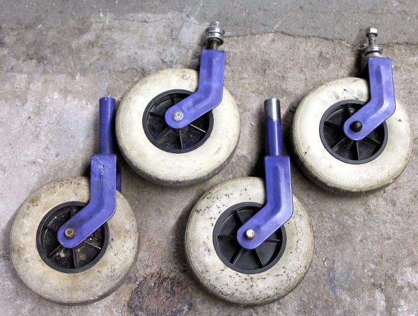
- 14.12.2018: Recycling wheels from an old rolator to use for<Balsi>. These wheels have 200 mm diameter. Maximum load (on 4 wheels) is 135 kg.
- 16.12.2018: Construction of the bend holder for the orange rotating light. This light consumes 55 W at 12 V. The holder is made from a 1 meter long piece of flat stainless steel, 60 x 5.
- 17.12.2018: Side plates cut out and large holes (70 mm diameter) sawn. These plates are 10 mm thick stainless steel. The mounting holes for the orange light upper structure are 10 mm, accomodating four M10 bolts. The blue rotating light we had in stock seems to suffer from s stuck motor. We have to look for alternatives. Note that the use of blue rotating lights is illegal, as they are reserved for the police...
- 18.12.2018: Further work on the side plates: 70mm diameter holes cleaned, to allow blue light to shine on the sides. Two 25mm holes drilled on the undersides. The 4mm holes are for the cabling. Polishing.
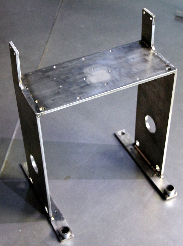
- 19.12.2018: Plates sawn and drilled for the wheel base. The holes are 15.5mm (backwheels) and 28.5mm (frontwheels). The 10mm diameter holes are for mounting the holder plates with the elecrtronic circuit boards. The plates are 10mm thick and will be electrode welded on the side plates.
- 20.12.2018: TIG welding of the wheel holding cylinders on the feet-plates. 10mm mounting holes for the electronics board holder drilled. Siren mounting plate further drilled, with provisions for the motorised fire alarm bell and the car horns. Welding of the main H-structure of the chassis.
- 21.12.2018: Straightening of the structure. First polishing session. Welding of the base plates with the wheels.
- 22.12.2018: Mounting of components on the upper chassis. Cutting of the middle mounting plate, curved, for mounting the power supply components. This is the 24V - 15A power supply:
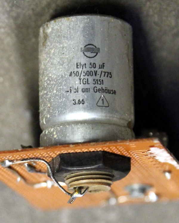
In trying out a high voltage power supply to drive the small siren with the universal motor, an electrolytic capacitor, 50uF - 450V, exploded right in our face. Although it blinded us for quite a while, Moniek was around in the workshop and could watch the enormous smoke stack evaporating from the aluminum capacitor can. It looked like a miniature H-bomb explosion. It was an old, but never used, capacitor, production date around 1966...
- 23.12.2018: Digged up two motorbike orange warning lights, very suitable to be mounted on the front side of the robot. The bulb sockets are BA15S, 12V. The yellow wire should be connected to the common +12V power and the green wire to the switching Mosfet output. De metal cap of the lite is connected to the green wire. However the mounting screw (M10 thread) is isolated from the lamp parts. Wiring for the hub board drawn out:
Power supply carrier plate welded in place, after completion of all the drilling. Test mount of components. Some polishing with sanding paper performed. The robot is slowly getting in shape now.
The bottom plate with the circuit boards is still missing here.
- 25.12.2018: Damper plate sprayed red. Horns mounted. Potential brake mechanism designed for the wheels, using two M20 bolts.
- 26.12.2018: Some wiring performed. The 12V / 10A Sunpower SMPS appeared broken. So we have to watch out for a suitable replacement.
- 27.12.2018: Design and calculation for an optical reflective sensor to use on the tacho input for the large siren. Sensor type is OPB742, the distance to the rotor blade surfaces of the siren should be 3.5 mm. The maximum range is between 2 mm and 7.6 mm. The data sheet for this component added to the references. Schaffner IEC mains entry module digged up. Modified circuit drawing for the motor board, with the new sensor:
We still have to find a solution for safely mounting the sensor on the siren.
- 28.12.2018: TIG welding of the back wheels on the chassis. Further wiring. Sawing of the mounting plate for the microprocessor boards in 8 mm thick transparent polycarbonate. Construction of a safe mains power entry using a Schaffner filter and IEC receptacle.. The fuses are rated 6.3A and are located behind the lid on the power entry. Still waiting for the replacement 12V SMPS to fly in from Farnell.
It doesn't look like <Balsi> will be playing before the end of the year...,
- 29.12.2018: Further wiring and work on the PCB mounting plate.
- 30.12.2018: Power wiring finished, apart from the 12 V supply that hasn't flown in yet. Hub board fully wired. Wiring motor board 1 almost done, but we run out of 2-pole Weidmueller connectors. Connectors and spiral wrap ordered from Farnell. It's unlikely we will have it before next year now...
- 31.12.2018: The 12V - 150W power supply came in today... Wiring can go on a bit. Still out of connectors. First electrical tests passed. No shorts, power voltages o.k., no unexpected behaviour. Firmware for the hub board version 1.0 ready to be flashed.
- 02.01.2019: The missing connectors came in from Farnell. All connectors mounted now. We still have to make one motor PCB and finish the wiring on the other boards.
- 04.01.2019: Finishing the hub board, version 1.0 of the firmware flashed.
- 05.01.2019: Finishing the first motor control board. Mosfets soldered in place are AUIRF3710Z types. Short specs: 100V/59A, RdsON = 0.018 Ohm, Ug = 10V. Data sheet added to the references.
First tests with our test code in GMT. Components working o.k. on the first run: Blue light, orange pinker light, rotating orange light motor, horns on hub board, ctrl.66, Problems encountered with following components: rotating orange light (bulb): other 12V powered components fail as soon as we start the PWM for the bulb. The siren motor does work, but needs a lot of fine tuning in the firmware. The bike-horn is not working. The laukhuff solenoid for the damper works in a very shaky way.
- 06.01.2019: Debug and problem solving session. Removing the PWM on the orange flashlight solves the problems on the hub board. Still, the IRL640 mosfet gets pretty hot after a while. Should we replace it wih a type having a much lower RgsON? Apparently the large ground return current, causes terrible glitches all over the board. The not working claxon on the motorboard, apparently has to do with either a not working ICL7667 chip or a bad connection on the PCB. Further investigations, after adding some bypass caps on the motor board, revealed that the midi data input is highly disturbed by the PWM spikes... We have to get the oscilloscope to the robot and check out grounding possibilities as well as snubber networks.
- 07.01.2019: Re-reading again the 'Fundamentals of MOSFET and IGBT gate drive circuits'... Motor circuit board examined again: we had a short between the two 'ground' planes! The 24V circuits oughts to be fully floating. This seems to have solved the hardware related problems with the siren. The claxon problem remains unvolved. Might be a shorted gate on the mosfet.
- 08.01.2019: The 7812 regulator on the motor board has gone to heaven. Could high voltage spikes on the 24V input side have caused the failure? MOV's as well as a 10uF MKM capacitor added on the board. On the output side, the current drawn is much under the allowable specifications. Design fault discovered in the circuit driving the ICL7667's from the optocoupler outputs. The 7667 requires a lower voltage for a logic 0. The 2V we measured was way to high. Here is the analysis of the problem and a possible solution:
As this involves some redesign of the PCB, we solved the problem on the existing board by soldering four 470 Ohms SMD resistors between the ICL7667 inputs and ground on the copper side of the PCB. This brings the logic 0 level down to 1.4V and the high level to 4.9V. Now it works. Design for the second motor board adapted, PCB board etched and drilled. Here is the board:
Start soldering works for this board. First tests revealed that the second drive circuit as shown above, was not working at all. We still do not understand what's wrong here though. The third circuit however did work and did not cause any changes on the PCB.
- 09.01.2019: Further soldering work of the second motor control board. Board finished, tested and mounted in the robot. First tests passed. Here is a picture of the finished board:
We have to limit the PWM values for the 220V siren to 50462, so ca. 77% of the maximum value. With the PWM at maximum, we measure 284V dc over the siren, higher than safe and acceptable. The motor bell works fine as is and does not need refinement. Siren 3 ordered from Farnell.
- 10.01.2019: Measurement and firmware improvement session. Range for siren 1 limited to functional and safe range. So now the note range is now 43 to 81. Damper bug solved: with controller 7 at zero, the siren was not working at all. So in the firmware, the minimum value is now 1. Note that with the damper open, note 81 cannot be reached. <Balsi> demonstrated for Mattias Parent and Lara Van Wynsberghe.
- 11.01.2019: The Klaxon siren came in from Farnell. Mounting of the device in the robot. Wiring completed. except for the sensor.
Now we can start improving the firmware and thinking about some music for the new robot.
- 12.01.2019: Working on the optical sensor and the PID mechanism. As to the optical siren on the large siren, the OPB742, we had a design error in the circuit, as we specified the collector resistor at 680 Ohms. With that value however, the output signal becomes smaller than ca. 20mV. Thus we changed the value to 100k, leading to a signal output in the order of 250mV. The disadvantage however, is that this raises the impedance considerably and thus the circuit becomes very sensitive for spurious interference signals. This dictated the use of shielded wire for the sensor connection to the motor board. The 100nF cap. is required, as the tacho chip expects an AC signal on its input.
- 13.01.2019: Sensor mounted on siren. Wiring completed. Analysis of circuit behaviour with the oscilloscope: the sensor signal haves very irregular. Far away in any case from the square wave we could have expected here. Most likely cause being the bumped surfaces of the siren rotor segments we use with our reflective sensor. Painting the aluminum rotor blades bright white may help, but still the bumps in the blades would cause errors. Also the output from the tacho circuit (spikes 225mV high, riding on a 75mV dc level) is not always triggering the interrupt input on the PIC. This must be a flaw in the circuit design. After some tweeking with the circuit, we got it to work and the interrupts happening. The pulses trigering the interrupt are about 16us wide. (pulse width = Vcc/2 .C1 / I2, where Vcc= 12V, C1 = 500pF, I2 = 180uA). However, a serious catastrophy happened: something mechanical failed in the siren, as it refuses the follow the motor now. The freewheel mechanism broke. Looks like we will have to disassemble the siren and see whether it is repairable. Otherwize we may have to watch out for a new identical siren...
Our first 'simple' repair appeared to be a failure:
We finaly inserted a 4mm diameter cilinder spring here. Let's hope it holds... Reassembly of the dented wheels:
- 14.01.2019: Bug found in the implementation of controller 25 for the small siren. PIC reprogrammed. Lookup tables for sirens 2 and 3 programmed. Controllers 24 and 25 implemented such as to work with cent units.
- 15.01.2019: Start working on musical and interactive applications. The PID regulation still needs further development.
- 17.01.2019: Firmware for motorboard1 and 2 changed to use 14-bit pwm resolution and 7.3kHz base frequency in an attempt to get rid of the PWM noise in the siren motors. All lookup tables rescaled. Tests passed for motorboard 1. However, motorboard 2 gave serious problems and our toroidal high voltage transformer started smoking and went to heaven... Did the mosfet die? Yes, it did... Maybe use an IGBT instead? Trying to find a replacement for the transformer... The siren survived the adventure.
- 18.01.2019: Motorboard 2 repaired: IPP60R180C7 Mosfet found fully fused as well as the diode. Mosfet replaced with an IGBT, type IRGB14C40 (430V/20A) and the diode with a MUR4100 (1000V/4A). The transformer found burned out on the primary side. New transformer ordered. It has to be custom wound: 230V : 160V. at 200VA.
- 19.01.2019: IRGB14C40 is probably not the best choice, the gate voltage being maximum 10V. Here is our test circuit:
, and this is what we get to see on the oscilloscope:
With a 470 nF cap over the 24 V power supply lines, the positive spikes get halved. With a 470 nF cap over the inductance (the load), we get oscillations on both sides of the square wave, but the spikes vanish away. Even under these relaxed conditions, the IGBT gets very hot. The IKP15N60T (600 V / 15 A, made by Infineon) would be better selection. We ordered a few from Farnell...
- 20.01.2019: Continued analysis and research on circuit behaviour. Burned transformer replaced with a 250 VA toroidal with two 40 V secondary windings, series connected. No load voltage over the smoothing capacitor now reaches 188 V, quite a bit more than the expected and calculated value of 118 V. Board mounted in the robot again, still with the IRGB14C40 IGBT in place, and it seems to work again. Scaling in the firmware as well as in the GMT testcode needs to be adapted now.
- 21.01.2019: Tested under gesture control.
- 02.03.2019: Balsi photoshoot.
- 14.03.2022: Balsi tested again and found o.k. It has an important role in 'Eindspel', 2021 composition for the robot orchestra.
- 06.06.2023: More components similar to those in <Balsi> can be found in the newly finished <Rumo> robot. Some boards, originally produced for <Balsi> found a nice place in this <Rumo> robot.
References:- George Antheil, 'Bad Boy of Music', Da capo press, New York, 1981 (ISBN: 0-306-76084-3)
- George Antheil 'Ballet Mechanique', full score
- Laszlo Balogh, 'Fundamentals of MOSFET and IGBT Gate Driver Circuits, Texas Instruments, 2017
- Gillon, E. "Elektrotechniek", deel II: Elektrische Machines, ed.Standaard Uitgeverij, Antwerpen 1969.
- Edward Hughes, 'Electrical Technology', ed. Longmans, London 1960.
- Humphreys, Julian (ed.), Philips Power Semiconductor Applications, ed. Philips Export, Eindhoven 1991
- Block GNC24-15 24V/15A power supply
- AUIRF3710Z datasheet
- Infineon, IGBT datasheet.
- Infineon, IGBT IKP15N60T datasheet
Infineon, IPP60R180C7 datasheet- IR2104 datasheet
- IRL640 datasheet
- Kingbright KB847 optocoupler datasheet
- Klaxon Sirene datasheet
- LM2907 datasheet
- OPB742 reflective optical sensor datasheet (PDF)
- Paul Lehrman 'Introduction to Ballet Mecanique' (PDF)
- Raes, Godfried-Willem 'Bellenorgel' (1972)
- Raes, Godfried-Willem 'Expression control in musical automatons' (-2018)
- Raes, Godfried-Willem 'Logos @ 50, het kloppend hart van de avant-gardemuziek in Vlaanderen' (ed. Stichting Kunstboek, Oostkamp 2018)
- National Instruments, Linear Databook 3, Special Functions, LM2907, p.5-196 to 5-209, 1988 edition.
Order numbers spare parts and special (harder to find...) components:
- Bridge rectifier 40A - 1kV: 9380841 (Farnell) type CM40010
- 1mF/250V Electrolytic cap, snap in, PCB, Epcos B43501-C2108-M: Farnell 1839316
- 5-pole DIN socket, PCB, Preh metal 71251-050: Farnell ord: 1193184 (used as MIDI input connector)
- 5-pole DIN socket, PCB, Plastic Hirshmann MAB5 SH, Farnell ord.: 1944987 (used as MIDI balanced line driver output connectors)
- Schaffner 1:1:1 pulse transformers, type IT242 (2.5mH , 0.75 Ohm) usefull for PWM base frequencies <=40kHz, Farnell 1653529
- Schaffner 1:1 pulse transformers, type IT235 (3mH) have to be ordered specially.
- KB847 : Kingbright quad optocoupler
- Blue light: Compro, CO ST70 B024 4F (12-24V DC/AC, 120mA), CE ST 70 (Base), CO ST Stand60 (Mounting plate) (http://www.compro.de)
- Fire alarm bell: 12-30V dc, Made in China.
- Orange bulbs: BA15S sockets, 12V - 5 W
- Orange rotating light: 12V 55W, Halogen bulb
- Mains power entry, with filter: Schaffner FN372-6. This module houses two 6.3A glass fuses..
- 12V - 12A power supply LRD-150-12, Farnell order nr. 2815973
- Klaxon sirene, 24V - 0.5 A, 103dB @ 1kHz. Farnell order nr.8810303
- Werma horn, 24V - 70 mA, 92dB, Farnell order nr.:4336835
- 24V power supply: Block GNC24-15 (Farnell)
Cost calculation:
<Balsi>: Midi controlled large siren
Materials:
Purchase of a Polish military siren (flea market, used) Siemens 3-phase motor - not used PCB Motor controller board - rejected version Separation transformer 500VA - not used Version 2: Scooter motor, chain and gears 24V -15A power supply Block GNC24-15 Stainless steel plate 6200 x 200 x 10 (2 pieces) Stainless steel plate 50 x 400 x 10 (2 pieces) Stainless steel plate 50 x 1000 x 5 Stainless steel plate 450 x 200 x 10 Stainless steel plate 450 x 340 x 3 Toroidal 210V ac transformer, 150 VA Rectifier bridge 800V / 25A Electrolytic capacitor 200uF / 400V 12V - 12A power supply LRS-150-12 Hub board -PCB and components Motor board 1 - PCB and components Motor board 2 -PCB and components 12V - 25A relay Orange rotating alarm light Blue flashlight CO ST 70 Car/Motorbike horn 24V Motor driven alarm bell Rolator (purchased for wheel recycling) Welding electrodes 3.2mm stainless steel Argon gas for TIG welding Bolts and nuts Schaffner IEC mains entry block with filter and fuses Reflective optical sensor OPB742 Weidmueller connectors and spiral wrap 2 alarm horns 12V 1 Werma horn 24V 1 Klaxon sirene, 24V 0.5A 103dB Total: Labor:
Disassembly and cleaning of siren 1d PCB design of motor controller board V1.0 2d PCB revision V1.2 1d Firmware development 10d Version 2: construction of mounting plate 2d circuit design 4d pcb design motor boards 3d Firmware motor board 1 10d Firmware motor board 2
6d Firmware Hub board 4d Chassis construction 14d Wiring 5d GMT testcode writing, debug and test 8d Total nr. of working days 70d 14000.00 Endsum: 18903.61 Euro
Last update:2023-06-06