Microtonal
Musical Robot
Research project on
the development of new tools for musical expression at the University
College Ghent

|
|
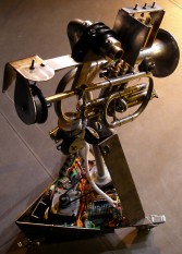
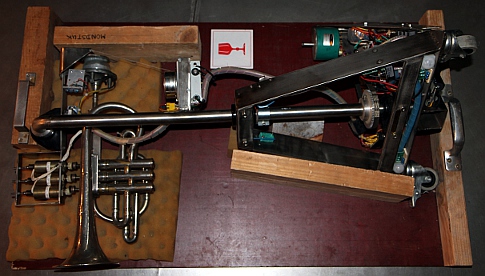
<Korn>
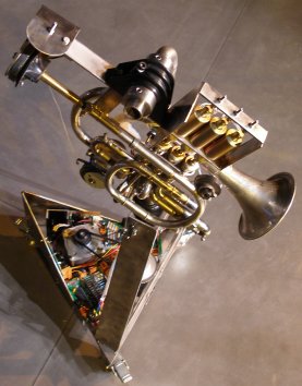
a robotic and moving Bb cornet
dr.Godfried-Willem
RAES
2008-2010
|
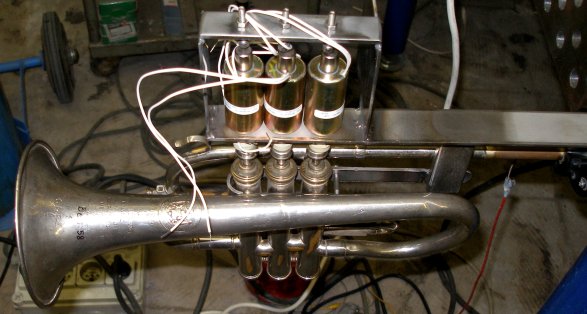
This musical robot belongs to the category of our more experimental instruments.
The experiment was not so much an attempt to realistically automate an existing
instrument, although it does in fact make use of an old Bb cornet and there
is an attempt to get a realistic cornet sound. In this case however, we did
not start with a mechanical design for an artificial embouchure with mouth,
lips and mouthpiece coupled to and in acoustic interaction with the tubing of
the instrument, as we have done in <So> and the first version of <Bono>,
but rather used a small motor-speaker compressor directly coupled to the cornet
via a capillary. The motor driver causes resonance in the cornet tubing, but
in this case there is no real windflow through the instrument. When a note is
requested from the cornet, the firmware will calculate the optimum valve combination
-including non orthodox fingerings- for the requested pitch. Microtonal pitches
are implemented such that the instrument is capable of performing quartertone
music, as well as a wide range of different tunings and temperaments with great
perfection. The relatively low Q-factor of the horn (compared to strings...)
as an acoustic resonator renders this very well possible. The signal generated
in the motor was shaped after a physical model of the air pressure waveform
in the mouth cavity of a player. Since there is no loop coupling from the resonator
to the generator, the sound generation mechanism is a hybrid somewhere between
synthetic/electronic and natural/acoustic. The advantage being that the reliability
of the robot becomes very high, but this is obtained at the detriment of realism.
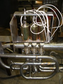
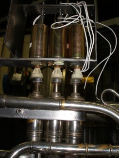
The valves are used in this instrument to tune the fundamental frequency of
the instrument. The valves can be controlled independently from the mouth driver
frequency. They are mechanically driven by unipolar solenoids (Lucas-Ledex types
as used in our player pianos) and have a return spring. Bi-directional solenoids
would have been superior (read faster and more silent in operation due to the
absence of return springs) but we just did not have enough mounting space in
this rather small instrument.
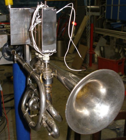
High brass instruments in their normal human biotopes tend to move quite a
bit in space. The highly directional characteristic of these instruments make
this also an expressive valuable parameter. Thus we tried to implement movement
in two degrees of freedom in this robot: the cornet can be tilted in the vertical
plane over an angle of about 90 degrees and in the horizontal plane, it can
rotate over 180 degrees. This conforms pretty well to what human players do
in terms of movement on stage. The movements cannot be very fast however, at
least not much faster than what a real cornet player could do whilst playing.
Horizontal movement is a lot faster than the vertical movement. However, the
intention never was to render Doppler effects possible...
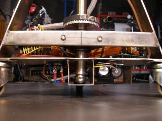
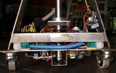
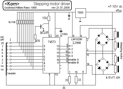
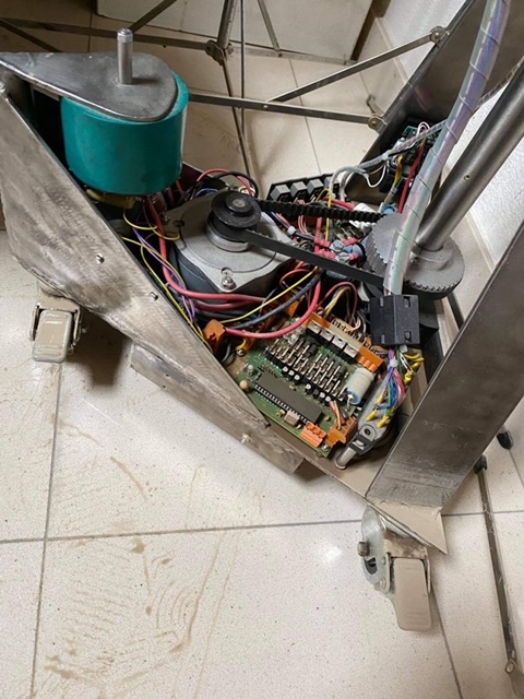
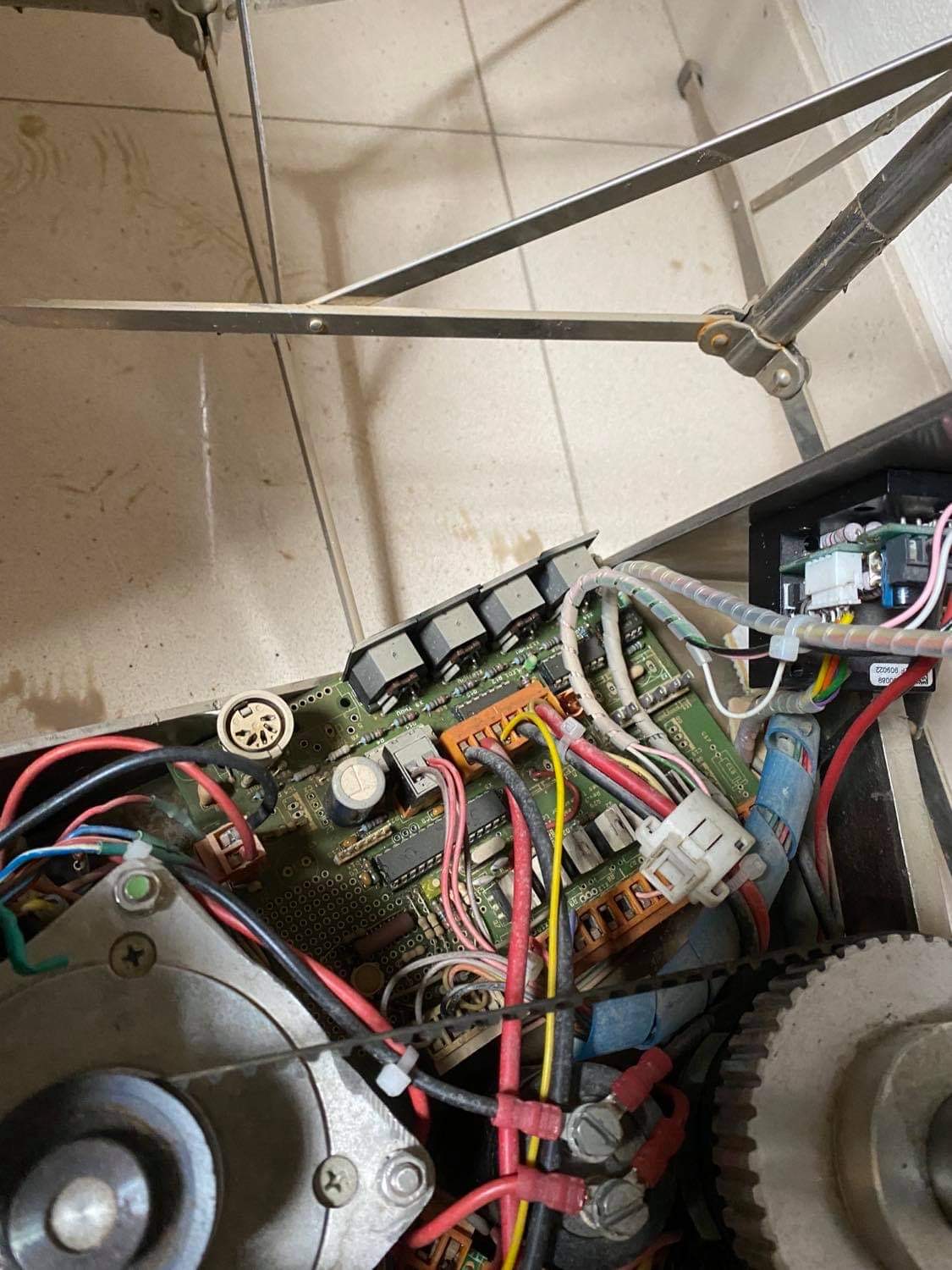
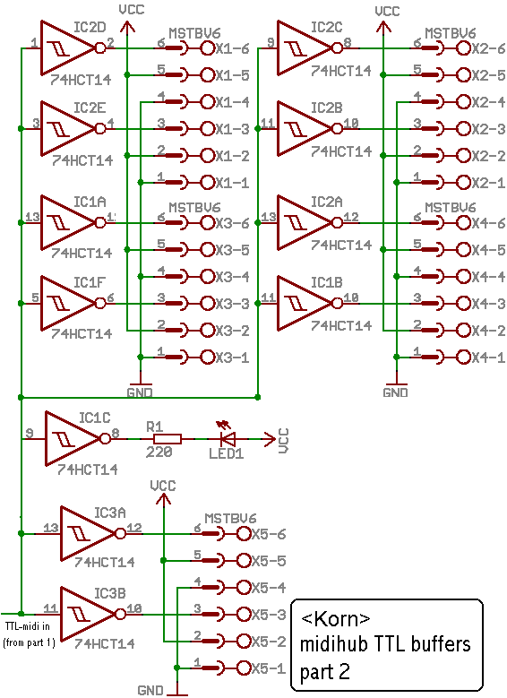
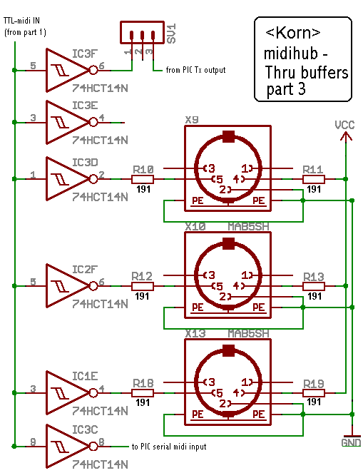
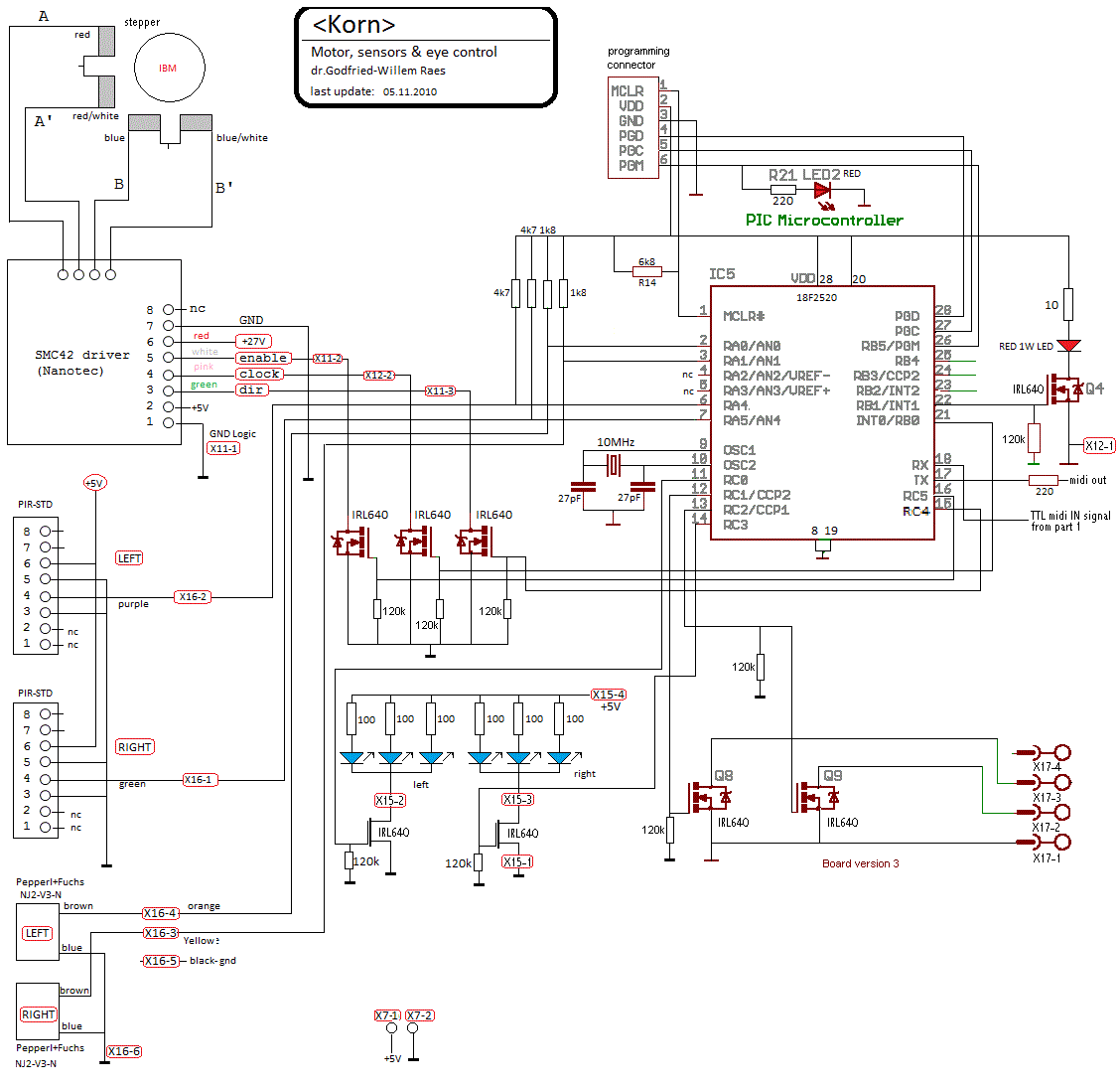
The electronic circuitry consists of four PC-boards:
1. Midi-hub board: This board, using a Microchip 18F2520 controller, takes
care of the Midi I/O handling and communication as well as the control of some
of the the lights and the movement of the horizontal movement stepping motor,
including the two end sensors. For these we used two Pepperl & Fuchs inductive
proximity sensors (NJ2-V3-N) . Provisions were also made for two PIR-sensors
allowing the robot to 'search' in space for moving human bodies. The output
data from these sensors can either be routed to the commands for the horizontal
stepping motor or output as a midi data stream. Circuit details can be found
at the very end of this webpage.
2. Horizontal stepping motor driver board using a Nanotec SMC42 compact microstep
constant current driver. The noisy fan was removed as well as the DIN-rail mount.
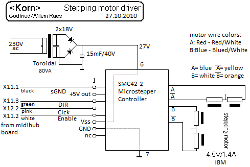 This motor
is designed for 360 steps for a complete rotation. In this robot, the motor
is driven in microstepping mode at 8 clocks for a single step.
This motor
is designed for 360 steps for a complete rotation. In this robot, the motor
is driven in microstepping mode at 8 clocks for a single step.
3. Pulse & Hold board: This board steers the three solenoids for the pistons
as well as the vertical movement stepping motor. Component population on the
board was modified to accommodate for required position sensors for the motor
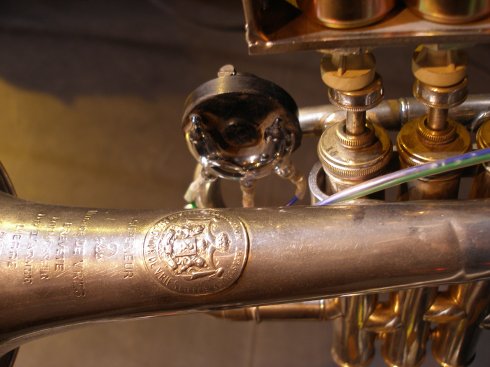
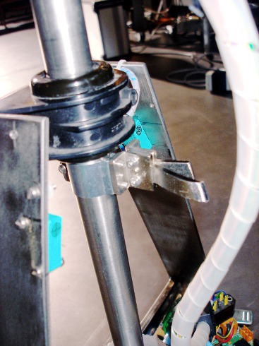
movement. For position sensing in the vertical plane we first used a beautiful
antique mercury switch with 3 contacts. This switch had a glass tube in a circular
shape filled with mercury. It was designed rotate over its 6 mm axis. However,
the binary nature of this switch in combination with lost steps on motor slip
made precize positioning problematic. Thus, in 2010, we replaced this switch
with a Penny+Giles analog tilt sensor connected to the an0 analog input of the
PIC microprocessor.
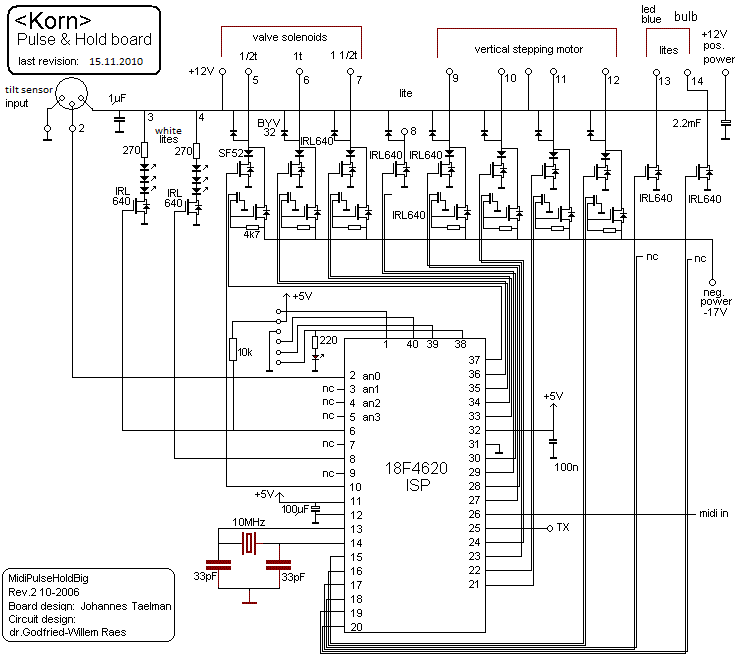 The light
bulbs and LED's mapped on the midi notes 124 to 127 are also controlled by this
microprocessor board.
The light
bulbs and LED's mapped on the midi notes 124 to 127 are also controlled by this
microprocessor board.
4. Sound generator board: This board, using a microchip ds-PIC 30F3010, steers
the 15 Watt motor compressor horn driver. Note that the output transformer forms
a tuned circuit, tuned to the formant band of the cornet (1.8 kHz). The transformer
at high sound pressure levels, operates close to saturation, thus causing a
formant shift upwards. When a coil gets into saturation the inductance decreases.
This clearly nonlinear behavior of the circuit was part of the design.
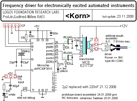
The wave forms generated in the firmware on the pwm1 and pwm2 outputs of the
controller are PWM based modified sinewaves in opposite phases. The carrier
frequency is around 20 kHz.
Power supply voltages and currents:
- +12 V dc (5 A) for the valve solenoids, sound driver and lites
- -18 V dc (5 A) for the valve solenoids and the vertical stepping motor
- +5 V/ 1 A for processor boards
- +26 V/4 A for the horizontal stepping motor (non stabilized)

Midi Mapping and implementation:
Midi channel: 12 (fixed in the firmware)
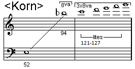
Midi note range: 52 to 94. (Optimum sound in the range 66-89) Note on, velocity
is implemented and has a wide control range. The most realistic sounds are obtained
in the 100 range for the velocity byte.
Note Off commands are required, but can be dropped for pure legato playing.
Controllers:
Controller 10: (Panning) Horizontal movement controller. Value 64: center,
127->0= move left (CCW), 0->127=move right(CW). The firmware will calibrate
on each of the extreme positions (0 or 127). The full semicircle takes about
2 seconds in time. The firmware assumes that after a cold start, the cornet
is in a central position. It will recalibrate whenever an endposition is encountered.
Controller 13: [to be implemented] changes the lookup
table for the valve-pitch correspondence. The default
is 0 and conforms to an empirical mapping of valve combinations for optimal
resonant sound. Value 1 selects the theoretical valve combinations calculated
after simplified acoustic theory, values 2 and 3 select user programmable (sysex)
lookup tables. Higher values can be used to send just
any valve combination the user wants to see used for any note. The table below
gives all details:
| Ctrl 13 Value |
-1/2t |
-1t |
-1 1/2t |
remarks |
| 0 |
|
|
|
default empirical [detailed mapping] |
| 1 |
|
|
|
acoustic [detailed mapping] |
| 2 |
|
|
|
user table 1 (sysex programmable) |
| 3 |
|
|
|
user table 2 (sysex programmable) |
| 4 |
off |
off |
off |
4-7 valid |
| 12 |
on |
off |
off |
12-15 valid |
| 20 |
off |
on |
off |
20-23 valid |
| 28 |
on |
on |
off |
28-31 valid |
| 36 |
off |
off |
on |
36-39 valid |
| 44 |
on |
off |
on |
44-47 valid |
| 52 |
off |
on |
on |
53-56 valid |
| 60 |
on |
on |
on |
60-63 valid |
| other |
|
|
|
invalid |
Using this controller it is also possible to change the fingering for a sounding
note whilst it is sounding, thus rendering some sound coloration possible
without changing the actual pitch.
Controller 17 is used to control the maximum sound level during the attack
period and as a general volume controller while the note is playing. (Note that
when this controller is set to 0, you can't play any notes. For a dal niente
crescendo, start from value 1.) A good default setting to start working from
is 90.
Controller 18 is used to control the duration of the note attack. The interdependencies
of these controllers together with the velo byte is shown in the graph below:
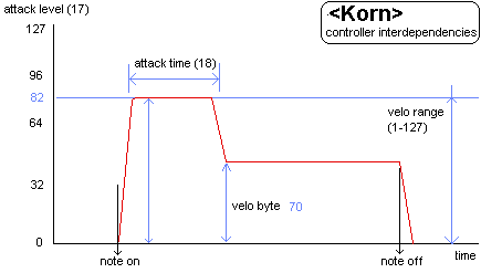 A good default setting
for this controller is 105.
A good default setting
for this controller is 105.
Controller 19: Release controller: to be implemented.
Controller 22: Vertical inclination controller. Value 64: center, 63-0= move
down, 65-127=move upwards. Note that downward movement is twice as fast as upwards
movement. The traject is less than 90 degrees. The traject will be recalculated
whenever the endposition read by the sensor is encountered. Thus, when you request
shaky movements, the traject will be very limited because of the bouncing of
the sensor that this causes.
Controller 25: valve movement force controller. With value 18, the movement
is smooth and a bit sluggish, whereas with 127 it may get noisy but very fast.
With values below 18, valve movement may become a bit unpredictable since the
movement will depend on wear, temperature, return spring force variations and
greasing of the pistons. After a cold start, this controller will be in a default
64 position.
Controller 31: Motor speed for the horizontal motor (left-right movements).
The speed can be varied between a fixed minimum value and a (safe) and fixed
maximum value. Value 0 sets the horizontal motor to move at the slowest speed.
Controller 32: Motor acceleration/deceleration time. On cold boot this controller
is always set to 64. Larger values lead to a longer acceleration time on horizontal
motor movement starts as well as to longer slowdown times at approaching the
destination. Acceleration and deceleration are always symmetric. As a consequence,
small movements will be performed slower than longer trajects.
Controller 66: Power on/off switch (0 = off, any other value is on)
Controller 67: brings the horizontal motor to the extreme left position (parameter
value =64). The controller is a one shot and does not need a reset. Any other
value than 64 is disregarded.
Controller 68: brings the horizontal motor to the extreme right position (parameter
value = 64). The controller is a one shot and does not need a reset. Any other
value than 64 is disregarded.
Controller 70: Calibrates both the vertical movement motor to a horizontal
position as the horizontal position to a straight forward position. This command
should only be sent on a full stop of all motors, i.e. no other midi motor related
commands should be sent during this calibration. The parameter can be any non-zero
value. This calibration also takes place automatically after a cold start of
the robot. Do not use this controller in any sequenced composition.
Controller 71: Recalibrates the horizontal motor movement only and brings the
instrument back to a full frontal position. During calibration no other motor
related midi command should be sent to the robot.
Controller 90: used to select movement interactive modes. With value 0 this
feature is switched off. Possible values are 1,2 and 3. More interactive modes
may be implemented in the future. The movement data are derived from the two
PIR sensors mounted in the front of the instrument.
Controller 100: Midi output mode setting. (See further below). Defaults to
zero.
Controller 101: Midi output data rate. See below.
Controller 123: switches the sounding note off, unpowers the steppers, dims
all the lights.
Program change: not implemented so far
Lights: The lights are mapped on very high midi-notes as follows:
- note 127: triple bright white LED on pulse-hold board with PIC2 (on/off)
- note 126: triple bright white LED on pulse-hold board with PIC2 (on/off)
- note 125: Blue 6-LED light assembly, mounted near mouthpiece driver (PIC2)
(on/off)
- note 124: Harley Davidson tungsten light bulb (PIC2) (on/off)
- note 123: Bright RED led mounted on the hub board
(PIC1). The velo byte sets the flashing speed. 0= off, 127= fully on.
- note 122: Left eye blue LED's (PIC1)The velo byte
sets the flashing speed. 0= off, 127= fully on.
- note 121: Right eye blue LED's (PIC1)The velo byte
sets the flashing speed. 0= off, 127= fully on.
Pitch bend: The <Korn> robot can be used in any tuning system. In the
drawing below we give the coding example for a quartertone scale:
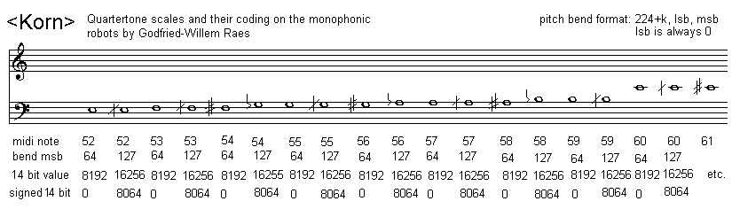 Most good sequencer
software (such as Cakewalk or Sonar) use the signed 14 bit format. Note that
one unit of the msb corresponds exactly to a 0.78 cent interval. To convert
fractional midi to the msb only pitchbend to apply follow following procedure:
if the fractional part is <= 0.5 then msb= 63 + (FRAC(note) * 128), if the
fractional part is larger than 0.5, we should switch on the note + 1 and lower
the pitch with msb= (1-FRAC(note)) * 128. Note off does
reset the pitch bend for the playing note!
Most good sequencer
software (such as Cakewalk or Sonar) use the signed 14 bit format. Note that
one unit of the msb corresponds exactly to a 0.78 cent interval. To convert
fractional midi to the msb only pitchbend to apply follow following procedure:
if the fractional part is <= 0.5 then msb= 63 + (FRAC(note) * 128), if the
fractional part is larger than 0.5, we should switch on the note + 1 and lower
the pitch with msb= (1-FRAC(note)) * 128. Note off does
reset the pitch bend for the playing note!
Midi OUTPUT control:
Data from the PIR sensors can be output as midi data
as well as data with regard to the position of the robot in space. A controller
(#100) has to be sent to Korn to enable midi out. This feature is meaningless
for composers using sequencing programs, but can be very welcome for composers
wanting to develop interactive applications using programming languages such
as Power Basic, GMT or even PD. The implementation is as follows:
Controller 100: Midi output mode. The data byte consist
of 7 bits (0 to 6), each used as a switch to enable/disable particular midi
output streams.
- 0 = OFF (midi out is disabled) This is the default.
- bit 0 = Left PIR sensor data is output: Left sensor
is output as 14 bit pitchbend on midi channel 0. The data is an 8 bit value.
Sampling rate can be set with ctrl.101
- bit 1 = Right PIR sensor data is output as pitchbend
on midi channel 1. The data is an 8 bit value. Sampling rate set with ctrl.101.
Sampling rate maximum: 154 S/s
- bit 2 = Motor position monitoring. The data covers
the entire traject (0 - ca.. 1480). Output is on midi channel 2. Sampling
rate 38 S/s
- bit 3 = Monitoring of the left movement proximity
sensor. The data is 10 bits. Midi channel 3. Sampling rate 154 S/s
- bit 4 = Monitoring of the right movement proximity
sensor. The data is 10 bits. Midi channel 4. Sampling rate 154 S/s
- bit 5 = Monitoring of the loopspeed in the firmware.
Output is in pitchbend format with only the lsb of the timer0 value (for debugging).
Midi channel 5. The output data rate is the loopspeed plus the time required
for the midi output itself. (ca. 1 ms) [implemented for firmware debugging
only]
- bit 6 = Monitoring of the Soll position for the motor
(destination value). Midi channel 6.[implemented for firmware debugging only].
Other values are implemented for internal research, firmware
debug and development purposes. Note that on start up and calibration, the available
motor traject in steps is always output using the pitchbend format, even when
controller 100 is set to zero. The traject is in the order of 1480 steps.
Controller 101: Use to set the data rate for the midi output of the PIR sensors.
The values accepted for this controller are between 1 and 8. The default value
is always 4. The meaning is as follows:
- data rate ca. 1.2 Hz value = 1
- data rate ca. 2.4 Hz value = 2
- data rate ca. 4.8 Hz value = 3
- data rate ca. 9.6 Hz value = 4
- data rate ca 20 Hz value = 5
- data rate ca 40 Hz value = 6
- data rate ca 80 Hz value = 7
- data rate ca. 160 Hz value = 8
Technical specifications:
- size: height 800 mm, depth 400 mm, length 400 mm.
- Flightcase size: 950mm x 590mm x 390mm.
- weight: 17 kg.
- transportation: needs its flightcase. Cannot be taken as luggage in airplanes,
since the weight with case is over 35kg.
- Power: 230 V ac / 150 W
- Note: on cold boot is is mandatory that the cornet is positioned in its
central position, without touching any proximity sensor.
- Tuning: based on A = 440 Hz (within 1 cent). The tuning can be adjusted.
- Ambitus: 52-96 (optimal range: 58 - 87)
- control: MIDI-input, 3 MIDI-Thru, 1 MIDI-Out. (UDP port to be implemented
later)
- Insurance value: 8.500 Euro.
Design and construction: dr.Godfried-Willem
Raes
Collaborators on the construction of this robot:
- Kristof Lauwers (GMT implementation)
- Johannes Taelman (dsPIC coding)
- Yvan Vander Sanden (controller testing)
Music composed for <Korn>:
- Sebastian Bradt "Barbiefication" (for <Korn> and <Xy>)
(2008) [MP3 download]
- Godfried-Willem Raes "Sires Hands" for <Sire> and <Korn>
and a performer with the Handy One interface
- Godfried-Willem Raes "Just
Calls for Brass" (in just intonation, with <Bono>, <Heli>
and <So>)
- Yvan Vandersanden "Interaktief stuk voor <Korn>, <Snar>
en Wii kontroller" (2009) [MP3
download]
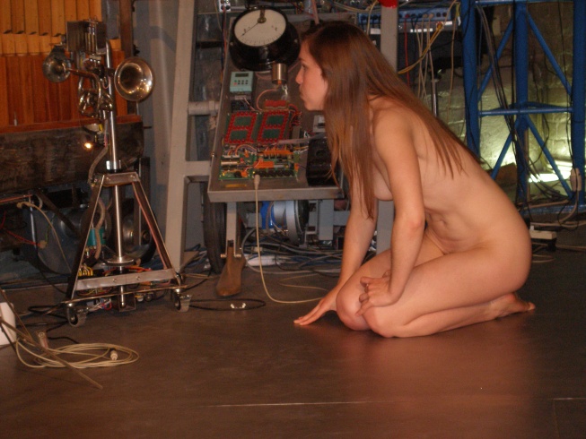
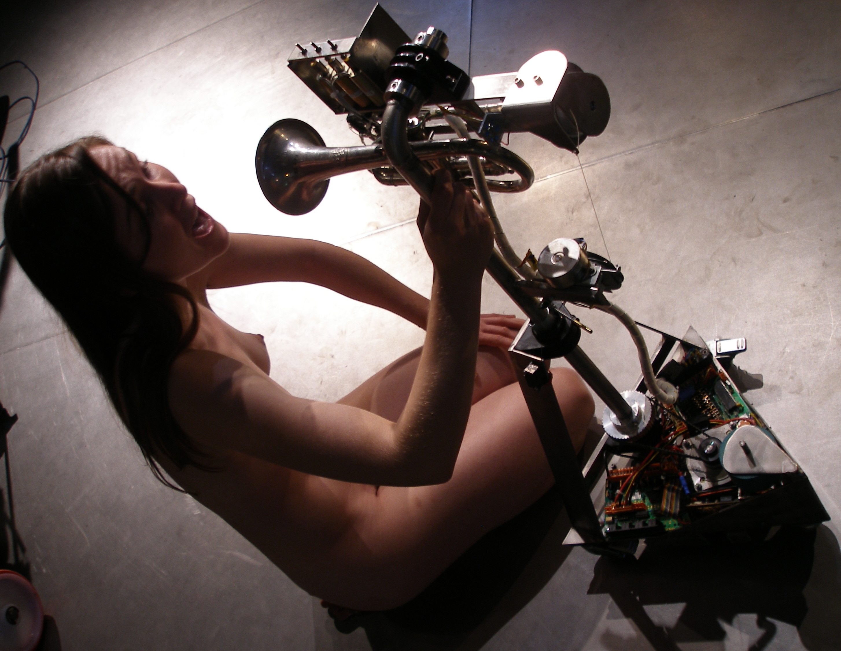
- Godfried-Willem Raes "Gesti for Korn", quadrada study #19 for
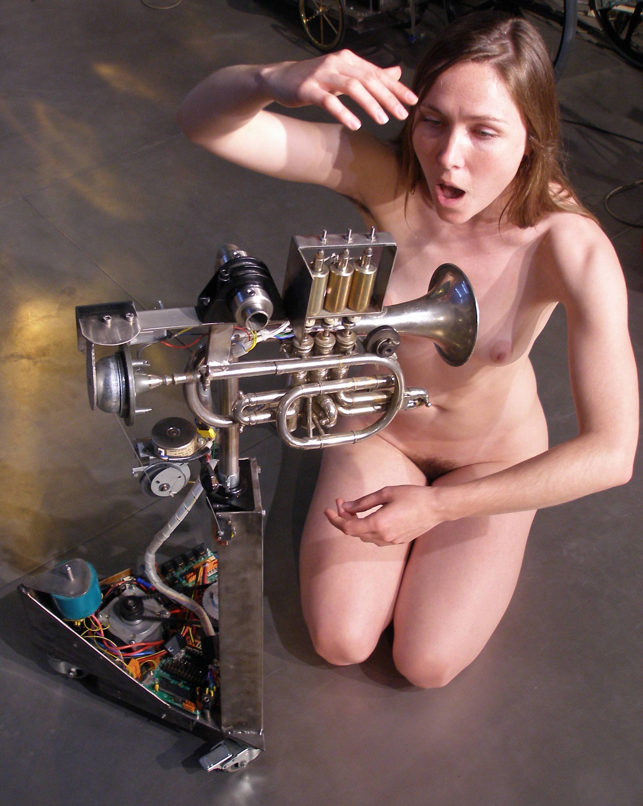
a naked performer and <Korn>. Staged in collaboration with a.rawlings
(2009)
- Kristof Lauwers "Picrada Study for Korn".(2010)
- Godfried-Willem Raes "Moves for Korn". Staged in collaboration
with Dominica Eyckmans (2010).
- Godfried-Willem Raes "Zwiep & Zwaai". (2010)
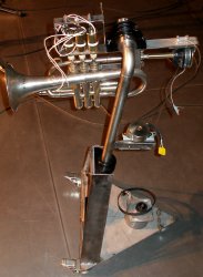
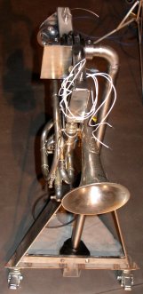
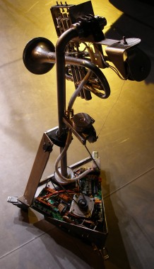
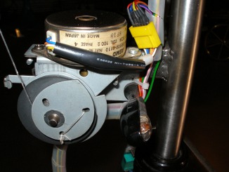
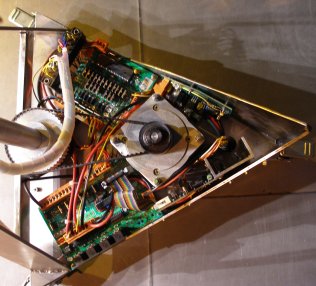
Pictures taken during the construction in our workshop:
Nederlands:
<Korn>
De overgrote meerderheid van de muzikale robots die we ontwikkelden
voor 2007, waren elk voor zich pogingen om bestaande akoestische instrumenten
zo getrouw mogelijk te automatiseren in zoveel mogelijk aspekten van hun bespeling.
Daartoe mimeerden we zoveel als mogelijk de menselijke bespelingswijze van deze
instrumenten. Het <Korn> projekt wijkt van dit opzet in hoge mate af.
Hier was het helemaal niet onze bedoeling een mimetisch bespeelde automatische
kornet te bouwen (immers, een automatische Sousafoon -<So>- hadden we
reeds met redelijk sukses voltooid, waardoor een automatische kornet niet direkt
een nieuwe verwezenlijking zou zijn). Niettemin maakt deze robot wel degelijk
gebruik van een oude Sib kornet die hier evenwel in eerste plaats dienst doet
als afstembare resonator in een instrument dat verder alleen werd gekoncipieerd
om min of meer realistische kornet-geluiden op een plastische en kontroleerbare
wijze te kunnen produceren. In dit ontwerp werd uitgegaan van het simuleren
van de drukvariaties in de mondholte van de bespeler en in het mondstuk middels
een elektronisch aangestuurde motor driver, zoals gebruikt in kleine megafoons.
Wat hier ontbreekt is de terugkoppeling met de resonator die het instrument
zelf eigenlijk is. Het instrument fungeert hier als een passieve resonator en
is niet via een dynamische regeling gekoppeld aan de eigenlijke toonvorming.
Daardoor krijgen we enerzijds een heel hoge betrouwbaarheid, maar anderzijds
dan weer een toch wat synthetisch klinkend klankresultaat met weinig of geen
artefaktische bijgeluiden en een eerder stereotype gelijkmatige artikulatie.
Wat we van bij het ontwerp evenwel zeker geimplementeerd wilden zien was een
ruime gamma aan mogelijkheden op mikrotonaal gebied. Zowel kwarttoonsmuziek
als muziek in de platonische juiste boventoonsstemmingen diende perfekt speelbaar
te zijn. Om die reden kan deze robot heel goed overweg met alle niet-standaard
vingerzettingen. Akoestisch gezien wordt dit mede mogelijk gemaakt door de relatief
lage Q-faktor van de licht konische toeter gezien als akoestische resonator.
De ventielen werden geautomatiseerd met unidirektionele elektromagneten,
helemaal naar plan en opzet zoals toegepast in de eerste
versie van <So>. We hadden liever bidirektionele magneten gebruikt,
maar daarvoor vonden we gewoonweg geen plaats in een zo klein instrument als
de kornet. De ventielen werken dan ook met de gewone terugslagveren.
De elektronische schakeling bestaat uit enkele afzonderlijk funktionele
boards:
1. Midihub board; Dit board, uitgerust met een 18F2520 PIC-controller
van Microchip, staat in voor de midi-kommunikatie en voor de besturing van de
horizontale stappenmotor. Twee ingangen worden gebruikt voor het inlezen van
de horizontale positiesensors. Daarvoor werden aanvankelijk mikroswitches met
lange naaldhefbomen in veerstaal gebruikt, maar die werden in 2010 vervangen
door induktieve NAMUR proximity sensors van Pepperl+Fuchs. (NJ2-V3-N). Deze
sensoren worden analoog door de microprocessor ingelezen, waardoor we geen problemen
meer hebben met bouncing. Twee andere ingangen worden gebruikt voor het inlezen
van de data afkomstig van twee pyrodetektoren (PIR-sensors). Deze laten toe
de horizontale beweging van de kornet een menselijk lichaam in de ruimte te
laten volgen.
2. Stappenmotor besturings board, waarvoor gebruik werd gemaakt
van een Nanotech SMS42 module.
De motor, een type met 360 stappen per omwenteling, wordt bedreven in microstepping
mode aan 8 kloktikken per stap, wat een erg vloeiende beweging mogelijk maakt.
3. Pulse-Hold board voor de besturing van de ventielen evenals
voor de besturing van de vertikale stappenmotor. Dit board maakt gebruik van
een Microchip 18F4620 controller in 40pins DIL behuizing. De bestukking van
het board werd enigszins gewijzigd om de beide noodzakelijke inputs voor de
eindsensor van de motor mogelijk te maken. Voor deze sensor gebruikten we aanvankelijk
gebruik van een cirkelvormige driepolige kwikschakelaar voorzien van een 6 mm
as. Het onderdeel dateerde van vlak voor de tweede wereldoorlog.. Door de slip
van de motor in kombinatie met het louter binair karakter van de sensor kregen
we echter af te rekenen met problemen in het juist positioneren van de kornet.
Daarom vervingen we de kwikschakelaar in 2010 door een hellingssensor van Penny
& Giles (STT 280/60/P2) . Deze
sensor wordt analoog ingelezen door de A0 analoge ingang van de mikroprocessor.
en laat een erg nauwkeurige positionering toe.
De lampjes
en LED's gemapt op de noten 124 tot en met 127 worden ook door deze mikroprocessor
bestuurd.
4. Klankproduktieboard: Dit board werd uitgerust met een 30F3010
ds-PIC kontroller van Microchip. Dit board heeft ook een midi-out, dit in eerste
plaats omwille van de debug mogelijkheden. Opgemerkt moet worden dat de uitgangstransfo
hier een afgestemde kring vormt met een resonantie rond 1.8 kHz, overeenkomstig
de gewenste formant voor een kornet.
Aangezien een kornet op zich genomen een vrij klein en licht instrumentje
is, kwam de idee bij ons op om het ook meteen enige mate van beweeglijkheid
mee te geven. Deze beweeglijkheid behoort immers ook tot het typische geluid
van de hoge koperblaasinstrumenten, die immers zonder uitzondering een sterk
direktionele akoestische afstraling hebben. Hiermee konden we meteen Toshiba
& Yamaha de loef afsteken, want hun bewegende trompetspelende robot -die
wel zowat alle kranten haalde- is vals! Het geluid komt immers uit een luidspreker
uit de borstkas van de robot trompettist. Ook wilden we onze robot graag zo
gaan bouwen dat hij het zou vertikken om debiele muziek te spelen... Dat is
echter helaas nog steeds vapourware. Horizontaal kan onze robot 180 graden bewegen,
en vertikaal 90 graden. Hiermee mimeren we heel goed wat menselijke spelers
op het podium doen. Een erg hoge snelheid konden we voor deze bewegingen evenwel
niet realizeren, wat niet wegneemt dat die snelheid (horizontaal) zeker niet
moet onderdoen voor die van een menselijke bespeler. De vertikale beweging is
door de gebruikte wormwieltechnologie aanzienlijk trager. Het was dan ook niet
de bedoeling Doppler effekten mogelijk te maken.
De <Korn> robot werd gemonteerd op 3 rondom beweeglijke
zwenkwielen voorzien van remmen. Wanneer de remmen niet worden vastgezet tijdens
het spelen, kan de robot zich als gevolg van de eigen bewegingen ook wat over
het podium verplaatsen... een leuk maar eigenlijk onvoorzien neveneffekt.
Construction & Research Diary:
- 04.01.2008: first experiments with the sound generator devices: horn motor
compressors.
- 07.01.2008: Cleanup and adjustment of the cornet valves
- 08.01.2008: First experimental construction of a motor horn driver, taken
from an old megaphone. The sub-octave sounds (the real fundamentals of the
cornet) cannot be made to sound really good. Hence we decide to drop them
altogether.
- 10.01.2008: Construction carrier plate for the valve solenoids with 19 mm
holes in stainless steel.
- 12.01.2008: TIG welding work on solenoid assembly. Design of a holding structure
for the cornet such that we leave the possibility for the instrument to move
freely, open.
- 13.01.2008: Welding works on the cornet holding structure. Design of the
motor driver holder. First workshop pictures taken and added to this webpage.
- 14.01.2008: Selection of a suitable stepper motor for the horizontal movement.
For vertical movement, we could simply use a heavy solenoid combined with
a spring. These features will have serious consequences for the design of
the power supplies! Purchase of ball bearings for two axis of movement. Vertical
inclination will require a force of ca. 50N.
- 15.01.2008: Further design of support structure. Suitable stepper motor
maybe AIMS 24 V/ 100 Ohm/winding 4-phase motor with worm-wheel gears, if we
use a tiny wound steel or nylon cable for the vertical movement. This motor
comes from a recycled old Japanese photocopier. The advantage of this mechanism
is that no power on the motor is required to hold the cornet in any given
position. Problem to be solved: how can we safely connect the steel wire to
the barrel.
- 16.01.2008: Plasma cutting of ground plate. Welding support for vertical
movement motor. Design for wheels of the support block.
- 17.01.2008: Start cutting and welding works for the horizontal movement
mechanism. The main chassis is ready now, included the three wheels with breaks
under the equilateral triangle bottom plate. Heavy duty connector found for
the removable connection between moving upper part and the electronics on
the base plate. Toroidal transformer selected for power supply: 2x 12 V/ 5
A. This transformer can be mounted under the base plate.
- 18.01.2008: Turning work on horizontal dented wheel. Mounting of toroidal
transformer underneath. Drilling holes for the horizontal stepping motor mounting
bolts. Discussion of the sound mechanism and its PIC implementation with Johannes
Taelman.
- 19.01.2008: Horizontal motor mounted and adjusted. Positioning of PC -boards.
Mounting holes drilled. Threads for motor mounting (M5 studs) welded on bottom
plate. Two 90/60/30 triangles in 3mm thick stainless steel plate welded to
end point. These serve for avoidance of mechanical resonance's and for mounting
of the horizontal stepping motor controller. All welding performed with frequent
intermediate cooling with compressed air to avoid warping.
- 20.01.2008: Mounting and wiring of power supplies. Mounting of all required
PC-boards, except DS-PIC board. Midihub board soldered with component values
documented below (see end of this webpage). Mosfets exchanged for IRLZ44 types.
- 21.01.2008: Interboard connectors made. Design of end position sensors for
the steppers. Electrical testing of midihub board and motor controller board.
- 22.01.2008: Schematic for pulse-hold board redrawn. Soldering and component
selection and placement on pulse-hold board. Stainless steel piece bend, sawn,
polished and drilled with eyelet for the vertical movement. Mounting holes
24 mm apart, for M5 bolts. Bottom part large connected wired. Six ultrabright
LED's mounted on pulse-hold board, mapped on notes 126 and 127.
- 23.01.2008: Rotary mercury switch applied for vertical movement sensing
and positioning. The use of this part makes the robot illegal as an industrial
product in most of the civilized world. However, we had the part on our shelves
for at least some 40 years, before we finally found a good application for
it. Moreover, the part comes from military radio equipment from just before
the second world war. Orange light bulb (from a motor bike, probably Harley
Davidson) mounted on vertical motor assembly. This bulb has 10 Ohm cold resistance.
It draws quite a lot of current from the 12 V supply. Note that the mounting
uses an insulation feed through since the metal of the holder is connected
to one of the supply leads.
- 24.01.2008: All wiring finalized, except the ds-PIC board for the sound
driver. Microswitches for end-detection on horizontal movement added. Power
supplies tested o.k. Design of the ds-PIC board. Construction of a first prototype,
using a small audio transformer.
- 25.01.2008: ds-PIC board finalized and mounted. <Korn> is ready now,
except for the (ordered) 25 mm mechanical precision ring to hold the gear
wheel on the horizontal movement axis. The PIC programming works with Johannes
Taelman can take off... First firmware version for the PIC-controllers uploaded.
- 26.01.2008: First evaluation and test session. The code for the stepping
motors is still missing in the PIC firmware. The valve firmware works nicely,
the lights also. The ds-pic seems not working unless we reset it by applying
a pulse to pin1. This type of PIC appears to be extremely sensitive to spikes
on the supply lines. We remember having met similar troubles in the design
of <Bono>. The power delivered to the driver is 280 mW, when the power
supply voltage is 5 V. Thus, this voltage can safely be raised quite a bit.
Optimum sound is now obtained with following controller settings: Velo=38,
C17 = 127, C18=127. The calculated lookup tables correspond perfectly to optimum
horn resonance. So, there is no need to implement user lookup tables here.
However, different fingering can contribute to a more lively sound.
- Experiments with the ds-pic board: We raised the power supply to 24 V and
with a 10 Ohm series resistor, and connected it to our driver circuit. With
maximum controller settings, we have a voltage drop over the resistor of 11.4
V, hence a current of 1.14 A. Such a current clearly saturates (...and heats)
the transformer, with quite interesting sonic artifacts as result. An RC or
even LC combination might even sound better here, since it could give us the
possibility to tune it to the characteristic formant of the cornet. We tried
this, but the first results were very disappointing. So we conceived another
approach and calculated the integer number of the harmonic on the sounding
note that falls as close as possible within the formant of the cornet. For
this frequency band we assumed 2800 Hz, a value taken from literature on old
analog eletronic organ design books for the formant filters in cornet registers.
Obviously we need either measurements of our own, or more reliable sources.
The result of this calculation was added to the file describing the calculated
fingerings: lookup tables for <Korn>
(its a .txt file, not html!).
- 27.01.2008: The addition of a sub-partial corresponding to the base frequency
for each played note at about 30 dB below the level of the main pitch, contributes
greatly to a more realistic sound. Further experiments with the hardware circuit
led us finaly to the adoption of a hardware formant filter, designed around
the primary of the output transformer on the ds-PIC board. To do this, we
left the usual protection diodes (BYV32) out altogether and fitted a capacitor
calculated and measured to give a resonant frequency around 1.8 kHz. Soundwize,
this proved to be a major improvement, rendering the implementation of additive
formant components in the generated waveform unnecessary. If further filtering
and non-linear circuitry is required, it can now be done on the secondary
side.
- 28.01.2008: We digged up a spare part for the motor driver, in case the
one mounted gets overloaded in the process of the experiments. First work
on an algorithmic demo piece for <Korn> coded in GMT.
- 29.01.2008: Measurements of the real partials as compared to the platonic
ones shown here:
- 30.01.2008: Measurement and evaluation session by Kristof Lauwers. Pitch
bend range is now -50 to +50 cents.
- 01.02.2008: Dented wheel fixed on vertical column with pointed M3 bolts.
Solenoids definitive mounting and fixing. Replacement of felt washers inside
the pistons in order to silence their mechanical operation. Experiments with
LC-circuits in the primary circuit of the motor driver.
- 02.02.2008: Further experiments with formant filters in the drive circuit.
Whatever we attempt, it remains a very electronic and dull sound. The clicks
at the on- and offsets of a sound correspond to the tap tones on the mouthpiece.
The onset should definitely get a noise burst.
- 06.02.2008: Still a bit handicapped by pretty poor sound production and
lack of movement, <Korn> will already participate in a few pieces on
tomorrow's M&M concert.
- 08.02.2008: Preliminary premiere of 'Barbiefication' by Sebastian Bradt.
- 15.02.2008: Work session on DS-PIC code: clicks and glitches removed both
on note-on and note-off. Softer attack implemented. Wind-noise added. Octave
fault corrected.
- 16.02.2008: Composers manual updated in accordance with the latest midi
implementation.
- 21.02.2008: <Korn> participated in the mini-M&M concert in Schaarbeek
(Brussels).
- 01.05.2008: Further worksession on horizontal stepping motor for movement
with Johannes Taelman. Not yet working. We seem to be plagued by bugs...
- 02.05.2008: Horizontal movement is working now, under controller 21. Calibration
is automatic and happens everytime one of the endpositions is reached. Acceleration
curve and stepping speed are automated and not user programmable. The firmware
is optimized for low noise, smoothness of movement and sufficient torque.
Movement speed is 45 degrees of rotation per second. The controller works
positional: 0 corresponds to fully CCW and 127 to fully CW.
- 03.05.2008: GMT testcode for Korn updated.
- 10.05.2008: Working session with Johannes Taelman: vertical movement and
revision of the valve code. The first version was written in assembly, but
for this version we will use the Pic-C compiler. Controller 70 implemented
for vertical movement calibration. Vertical movement now works, but we still
have to rewrite the valve code and the relevant lookups. Stepping pulses on
downward movement are now. ca.20ms, whereas upwards they become 40ms. The
firmware uses only the velo-pulse outputs, so the hold mosfets are not used.
Because of the mechanical construction, the motor never had to develop a holding
torque, hence we could drop these components from the implementation.
- 12.05.2008: Working session with Johannes Taelman: code for velo-pulses
on valves ported to C on PIC2. To be done: Sysex-lookups for fingerings, further
improvement of the generation.
- 13.05.2008: 350 mA current source circuit built for 1 W super bright LED.
Forward voltage drop is 3.2 V as measured. Although the LED itself is pretty
small, if you take the complete required circuitry and cooling components,
there is something ridiculous about these components since at the end of the
bill, a normal tungsten light would have been both simpler, smaller and cheaper...
Light output is 10 lm, wavelength 470 nm
- 15.05.2008: 1W blue LED circuit mounted near mouthpiece driver and mapped
on note 125. However, it seems to cause glitches and resets on PIC2, caused
realignments of the vertical movement...
- 16.05.2008: Calibration command must still have a firmware bug. It should
read and monitor the mercury switch -after debouncing- to decide in what direction
to start rotating for alignment.
- 17.05.2008: An extra command should be added in the motor firmware: freeze
movement: ctrl. 71 (switch). This should work at the same time for the horizontal
and for the vertical movement. (PIC1 and 2). The freeze command should cancel
any ongoing movement.
- 12.08.2008: Consistent erratic behaviour. Sometimes actions take place without
any command... This led today to a complete burn out of the Harley Davidson
light armature. We replaced the lamp socket (was bayonet) with a standard
10mm screw socket and fitted a 12-15 V/160 mA tungsten bulb. After this repair,
it seemed some mosfets on the pulse hold board burned out... More work to
be done. Probably the solenoid driver mosfets burned out. There must be either
bugs in the PIC2 firmware or some other hardware failure.
- 06.09.2008: Further repair work on Korn. The Lucas-Ledex solenoid for the
first valve burned out and shows up a short circuit situation. We replaced
the solenoid. Tests under GMT control. Strange behavior observed from the
solenoids: bouncing... either something goes wrong with the PIC based timers
or the (Hold voltage) power supply is extremely unstable. First suspect to
examine: +5 V, then +12 V.
- 07.09.2008: Debug session. The faults are reproducible. Probability that
they stem from unstable +5 V is high. However, so far we couldn't see any
glitches on the scope. However, the +12 voltage shows up very high oscillation
( 4 Vpp), increasing with the load with period in the 5 microsecond range
(ca. 200 kHz). This oscillation disappears when we place a 2 mF electrolytic
over the output of the LT1084-12 regulator. The pulses in the ground return
current could be at the origin of the unstable behavior. The oscillation could
also explain the erratic behavior of the vertical stepper, since its mercury
sensors are fed with the same +12 V. Piher 2 mF/16 V elco and 1 uF ceramic
soldered into board. Now every thing seems up and working again. The 1 W blue
LED however seems not to have survived the failures...
- 08.09.2008: Korn monitored over longer timespans: calibrations on the vertical
motor still do happen at about every 5 minute rates. We have been monitoring
the 5 V supply and suspect it fluctuates at a very low frequency.
- 13.10.2008: New acoustic impedance convertor turned on the lathe. This brass
piece was made from the original cornet mouthpiece.
- 20.11.2008: The erratic behavior is persistent. We will have to replace
the Chinese SMPS (Sunpower) by a more sturdy modular design. Some more work
done on the sound determining circuitry. The <Bono> recipe applied to
Korn. (A single diode on the transformer primary). The capacitor has to stay
as it was. We now feed the driver from the available +12 V supply. The transformer
is heavily in overload, so we should look out for a more powerful part.
- 21.11.2008: To do: add an extra 5 V power supply for the horizontal stepper;
replace bright blue LED; search for a better audio transformer. Research and
measurement session on a MCE E217T3F precision toroidal multitap transformer
(Order number: 10018709), recycled from military aircraft.
- 22.11.2008: Origin of the erratic behavior traced down to very odd behavior
of the high power LED and its current drive circuit: the LED failed but still
caused very short very high current spikes on the 12 V supply, too short to
activate the current limits but so high that we could observe very large spikes
on the ground return leads, causing intermittent brown outs on the 5 V supply
feeding the PIC processors. We replaced the LED with a new assembly of 6 bright
blue LED's each drawing a current of only 11 mA. Mounting of the MCE multitap
transformer on the backside of the Korn chassis. This entails the addition
of a new welded chassis element. Circuit drawings adapted to the newest wiring.
The horizontal motor looks like working, despite the low power available from
our newly added 5 V dc power supply.
- 23.11.2008: Welding work on the construction and mounting of the new chassis
elements (carrier structure) for the MCE precision transformer. Capacitor
across transformer primary increased from 470 nF to 2.2 uF (bipolar). The
amplitude is now a lot more constant over the entire compass. Intermittent
oscillations on the pulse-hold pic board still occur. Ferrite RFI snubbers
fitted on the most important cable bundles. We suspect a bug in the implementation
of the very slow counters in the pulse-hold PIC firmware. Bug discovered in
the dsPIC firmware: Pitch bend is not reset on reception of a new note as
it should!
- 24.11.2008: Coding example worked out for quartertone scales:
GMT code and just intonation examples for Korn debugged.
- 26.11.2008: Test code for ctrl 13 added in GMT test by Kristof Lauwers,
for examination of the optimum fingering tables. However, ctrl. 13 is yet
not implemented in the pulse/hold board.
- 18.12.2008: <Korn> has an important part in my just intonation composition
"Just Calls for Brass".
- 21.12.2008: Further experiments with the tone production. Parallel capacitor
over the toroidal transformer changed again to 220nF, this capacitor must
be a high voltage type (100V). New power supply mounted for horizontal stepping
motor: now 9 V /1.6 A. This modular supply however, cannot cope with the pulsed
load from the stepper...
- 22.12.2008: New testcode written for the stepper motors. XP Power ECL25US09-E
power supply ordered from Farnell. This type should deliver 2.8 A at 9 V with
allowable peak current of 3.64 A.
- 23.12.2008: New power supply has arrived. We immediately build it in and
tested: the horizontal motor now behaves fully the way it should.
- 02.01.2009: The somewhat shaky behavior of the vertical movement motor is
persistent.
- 17.01.2009: Debug session on the firmware for the pulse/hold pic. The code
shows up some quite unpredictable behavior: at times the velo-pulse length
has jitter and may even double. The firmware had a tendency to crash for no
apparent reason. We temporarily disabled the code for the vertical motor.
The horizontal motor code (PIC1) must have some bugs as well. It does not
switch of motor power on reaching an end position.
- 28.01.2009: Apparently the sound driver died from overloads. Fortunately
we could recycle an identical driver from another Realistic power horn 8 Ohms/
8 W. After the replacement, Korn is working again, but when we measure the
maximum signal over the driver, it appears at 12 V that the overload is evident.
However, sound level is still way too low. We have to recheck the wave form
carefully...
- 01.02.2009: Further research on sound production in Korn. The sound gets
a lot better with a diode parallel over the otherwise not used secondary tap
on the transformer in combination with the 8 W driver. However, after constructing
an entirely new impedance converter on our lathe, adapted to a 15 Watt full
range driver, the sound became much better if we replace the diode with a
2.2 uF capacitor. This change also gives us a somewhat better dynamic range
as well as a better overload safety margin. Another minor, but nevertheless
most welcome, side effect of the new motor driver is that the instrument is
now mechanically more in balance over its axis of movement, thus relaxing
the forces to overcome by the vertical stepper motor.
- 02.02.2009: Demonstration of the renewed Korn for the collaborators. Evaluation
session.
- 05.03.2009: <Korn> on the road to Lille (France). It's only the second
time he is allowed to leave the logos building.
- 07.04.2009: horizontal movement sensors improved by mounting an adjustable
sensor-pin.
- 25.04.2009: Programming session with Johannes Taelman on the gestures for
<Korn>. Deep measurement and analysis reveals that to a large extend
problems with erratic behavior is due to spikes on the midi input signal,
stemming from the Midiman 2x2 device. The 4 port device does not show up this
problem. The erratic behavior can be predicted as soon as the green midi-monitoring
LED on the hub board glows slightly with the midi in cable connected but no
midi-data sent. To a large extend this misbehavior is due to the laptop power
supply.
- 26.04.2009: Horizontal movement tests.
- 02.05.2009: Worksession on the movement code with Johannes Taelman. Horizontal
and vertical movement is now well implemented. User fingerings also, using
controller 13. Lookup tables using sysex commands for fingerings are as yet
to be implemented.
- 03.05.2009: Testcode written for gesture tracking using the quadrada interface.
- 12.05.2009: Photoshoot with Korn.
- 13.05.2009: There must still be a bug in the midihub PIC firmware that causes
it to crash. This is the PIC responsible for the horizontal movement. Premiere
of 'Gesti for Korn' with a.rawlings.
- 15.05.2009: Loose cable on upperpart accidentally hitting the end switch
remedied. Kristof Lauwers and Yvan Vandersanden adding and debugging movement
code for Korn.
- 16.05.2009: Demonstration of <Korn> at Technopolis, Mechelen (Robocup).
- 23.05.2009: Debug session on the firmware for the horizontal motor controlling
PIC-microcontroller. The inherent hysteresis of the end-sensors caused logic
trouble. The bizarre crashes of the PIC every so often, are to be examined
further. They seem related to very high midi data rates.
- 24.05.2009: 'Gesti for Korn' rechecked with the Quadrada interface.
- 21.01.2010: Transportation bed made for <Korn>, not yet a complete
case.
- 22.01.2010: <Korn> travels to Breda for a concert...
- 12.02.2010: <Korn> is off to Hasselt for the Boink! festival there.
- 09-10.10.2010: <Korn> plays on the opening of the STAM museum on the
Bijloke campus: 12700 visitors...
- 26.10.2010: Start redesign of the horizontal movement mechanism: hardware
and firmware. Considering to add a Penny & Giles sensor for the vertical
movement as well, the same type as we just used for our <Ob> robot.
- 27.10.2010: Old stepper motor controller for horizontal stepper removed.
This will be replaced with a Nanotec SMS42-2 microstepping motor controller.
In the new design we will mount two PIR sensors for human movement detection.
- 28.10.2010: Two PIR sensors mounted. Midi hub circuit redrawn and rebuild.
As to the end sensors we selected Pepperl+Fuchs NAMUR types (NJ2-V3-N) as
we can operate these from the 5V supply and they have a reasonably large analogue
traject (ca. 6 mm). We designed a new sensing stave for Korn's central axis,
the pivoting part being made from weak iron. This will at the same time work
as a mechanical endstop.
The new parts can be seen on the picture. The applebluegreenish blocks are
the Pepperl+Fuchs sensors.
- 29.10.2010: Mounting work on the new components on the chassis.
- 30.10.2010: Fine adjustment of sensors and mechanism. Firmware works.
- 01.11.2010: First working version of the firmware more or less ready. Calibration
runs fine now.
- 02.11.2010: Voltages checked for stepping motor: without load: 27 V, with
running motor: 24 V. Now at firmware version 1.5. There are still some problems
with intermittent motor stops. The PIR-interactive coding needs some improvement
still.
- 03.11.2010: Firmware version 1.9: Stuttering bug killed. PIR coding now
works but there is still place for improvements. Midi implementation updated.
There is still a weakness in the dsPIC coding: this PIC crashes under unknown
circumstances. It may be related to induction spikes from the stepping motor.
- 04.11.2010: Further PIR testing. Controller 32 added to control the acceleration
curve for the horizontal motor. Controller 101 added for data output rate
control. Horizontal position controller number changed: now #10, the standard
panning controller in MIDI. As to the lights, we now also implemented automatic
flashing using the velo byte in the appropriate note on command. Firmware
version 2.0 now.
- 05.11.2010: 2 blue LED lights added as 'eyes'. Each 'eye'consists of 3 high
brightness blue LED's. Power consumption: 60 mA for each 'eye'. Mapping on
midi notes 121 and 122.
The PIR sensors as well as the new 'eyes' can be seen on the picture.
- 06.11.2010: Some minor fixes in the firmware again. Version 2.1 now.
- 07.11/2010: Deceleration on approach of final position now also implemented
in the firmware. Version 2.3 now. Controller 32 can be used to control the
acceleration/deceleration time.
- 14.11.2010: Cylinder for the vertical movement changed to 8mm diameter.
There is a lot more torque available now. This entails changes in the vertical
movement firmware.
- 15.11.2010: Penny & Giles tilt sensor mounted to replace the mercury
switch.STT 280/60/P2. Cornet fixed
in place with some silicone kit, as it had a tendency to move in its holder.
- 29.05.2011: Version 2.4 code revision for the midihub board, 18F2520 chip.
Periodicity in timers improved. Code optimised for speed of performance. Tests
run o.k. now and performance has indeed improved. Code revision session with
Johannes Taelman on the valve-control PIC, a 18F4620: vertical movement traject
improved and Penny & Giles sensor implemented.
- 06-09.10.2011: <Korn> presented and demonstrated on ArtBots Gent 2011
in the UFO building of Ghent University. It's been up and running for three
days in a row without any interruption.
- 09.10.2011: <Korn> received the Artbots award for the most succesfull
robot.
- 22.11.2011: Glissando playing now fully implemented in GMT
- 18.12.2011: <Korn> presented at the Childrens University, held on
the praemisses of the Ghent Conservatory.
- 14.03.2013: Start construction of a flightcase for <Korn>. This is
how the robot fits on the bottom of the case:
- 15.03.2013: Case under construction:
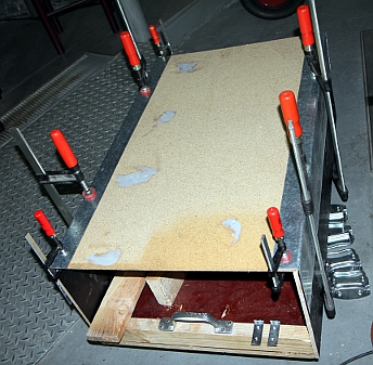
- 16.03.2013: Flightcase for <Korn> finished. It can now safely go on
the road in a truck. Case sizes are: 950 x 590 x 390
- 20.04.2013: <Korn> survived the trip to Glasgow very well! We expect
him back in Ghent on monday 22nd of april.
- 23.04.2013: Korn came back in good shape.
- 09.10.2013: <Korn> left this morning for its appearance on the Venice
Biennale on october 12th...
- 03.11.2013: <Korn> presented in Bozar for Zonzo.
- 05.11.2013: Connecting rope for vertical movement replaced as it got all
tangled and worn out.
- 02.03.2014: <Korn> makes his appearence at Concertgebouw Brugge on
the notation festival, together with <Snar> and the Player Piano.
- 18.10.2015: <Korn> played at the musica composer workshop in Neerpelt.
- 05-08.11.2015: <Korn> played four days continuously at 30CC in Leuven,
Rode Hond Festival.
- 17.12.2015: <Korn> gets to play important parts in our production
of the Beggars Opera by Bertolt Brecht and Kurt Weill.
- 9-11.04.2016: <Korn> off to Hamburg for the Big Bang Festival.
- 28.10.2016: <Korn> up to Brugge for Iedereen Klassiek.
- 30.10.2016: Korn returned safely from Bruges.
- 01.08.2017: <Korn> taken on the road to Liepaja (Letland).
- 03.08.2017: <Korn> found ok after the 2000 km trip to Letland. It
is expected to return to its homebase on august 10th.
- 09.08.2017: <Korn> returned safely from Liepaja, another 2000 km trip
on rough roads.
- 13.07.2018: <Korn> played the opening of the Ghent Feasts at Sint-Jacobs.
Returned safely.
- 09.11.2018: <Korn> joins the party for the 50th anniversary of Logos...
Rational Melodies, Namuda study #71.
- 17.03.2019: There was some confusion as to the ctrl nr for left-right movement.
The testcode had some bugs in this respect. The controller must be #10 (panning).
- 07.11.2019:<Korn> on the road to Tallinn (Estland)
- 02.07.2021: <Korn> on the road for Luxemburg
- 15.07.2021: Innundations in the abbey where <Korn> is installed...
Awaiting news.
- 19.07.2021: Some pictures received from the robots that got flooded in the
abbey of Neumuenster in Luxemburg:
 At first sight it looks
like the cornet and the driver didn't get wet. The electronics underneath
are likely to be lost forever. Certainly the hub board is lost. The wavegenerator
board is mounted vertically but cannot be seen on the picture. The pyrodetectors
for movement sensing are guaranteed to be ruined, as they were mounted very
low on the chassis.
At first sight it looks
like the cornet and the driver didn't get wet. The electronics underneath
are likely to be lost forever. Certainly the hub board is lost. The wavegenerator
board is mounted vertically but cannot be seen on the picture. The pyrodetectors
for movement sensing are guaranteed to be ruined, as they were mounted very
low on the chassis.
- 26.07.2021: <Korn> returned from Luxemburg. First of all we started
by cleaning the entire robot. Removing the thick layer of mud from all electronic
and mechanical parts. Tools used: a toothbrush, a small hard-haired painting
brush, compressed air, a small stainless steelbrush. The motor was found to
be completely stuck. This must be the result of a rusted anchor inside the
stepper. The toroidal transformer mounted underneeth, still contained water
in the windings. However, it was not short circuited. So we connected it to
the mains power -via a safety transformer- to let it get gently warm and thus
to dry it thoroughly.
- 27.07.2021: Continued work on the repair of <Korn>. We also noticed
the bell of the cornet got smashed quite a bit. This cannot be the result
of the innundation however. It must have been mistreated somewhere by someone...
After cleaning the hub board we could bring it to live again. So it survived
the catastrophe. The same revealed true for the dsPIC board for the membrane
driver and the horizontal steppermotor controller.
- 30.07.2021- 23.08.2021: Apparently the motor for the horizontal movement
is not quite healed. We can loosen it with heavy pliers, but after a day or
so it always gets stuck again.
- 24.08.2021: We removed the stepping motor and disassembled it completely.
Internally it was all wet, and this more than a month after the innundations
in Luxemburg. The stator and the anchor were found rusted strongly together.
Trying to repair it by carefully taking all parts apart and thoroughly cleaning
and repolishing of the poles. Here are some pictures of the disassembled stapper
motor: Rotor:
 Stator:
  Bearing
and under mounting plate:
Bearing
and under mounting plate:  Upper mounting plate:
  After assembling again and mounting it in place on <Korn>, the motor
passed all tests again. We expect it to be fully repaired now. The whole repair
procedure took us nevertheless about five hours.
After assembling again and mounting it in place on <Korn>, the motor
passed all tests again. We expect it to be fully repaired now. The whole repair
procedure took us nevertheless about five hours.
14.05.2022: <Korn> up and working, controlled by our 22GHz radar systems,
in Rennes, France.
- 22.07.2023: <Korn> returned safely and in good shape from the tango
production at the Ghent Feasts yesterday.
- 14.09.2023: <Korn> on the road with the robot orchestra for the Zeroth
Law production by Gamut Inc. at the Deutsche Oper Berlin.
- 02.10.2023: <Korn> returned healty and well from its trip to Berlin.
Last update: 2023-10-11
by Godfried-Willem Raes
The following information is not intended for the general public, but is essential
for maintenance and servicing of the robot.
Technical drawings, specs and
data sheets:
The moving upper part can be taken out of the base. First loosen the set screws
on the dented wheel as well as on the ring under the base plate, then pull the
rod out vertically. As an alternative one can also loosen the upper ball bearing
(two M6 bolts) and take out the vertical mechanism. This however requires realignment
of the ball bearing. Then, disconnect the large black rectangular connector.
The wiring is drawn below: 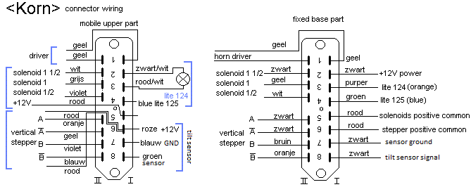
Horizontal Stepping Motor: Sanyo Denko Co. LTD, Step-Syn, type 103-820-2 (IBM
P/N 2526734) DC 4.5 V - 1.4 A, 2 degrees/step. Lot NR. 7749. Asmaat: 9.5 mm.
Drive belt: Gates, Powergrip 180XL.
Vertical Stepping Motor: ASMO, Type 865100-0110 Part number AX020009A, 4 phase,
100 Ohms/winding. Operating voltage: 24 V. Wire colors: white blue black, yellow
orange white. This component was recycled from an old Japanese photocopier.
Asmaat: 6mm, met wormwielvertraging.
MOSFET's: IRL640: Specs: 17 A / 200 V, logic level mosfet. (Ug = 5 V). No cooling
applied. IRLZ44N can be used as an alternative.
Solenoid type used for the valve pushers: Lucas Ledex (now distributed by Saia-Burgess)
STA type 195207-228 (13.8 V DC @ 100% duty), 10 Watt, 7.8 N @ 5mm with 60 degree
plungers. 26 mm diameter, height 52 mm. The required anchor displacement for
the cornet pistons is 16 mm.
Note on the push tubular solenoids used to activate the pistons:
The following specs are valid at 20 degrees Celsius. Maximum holding force
is 29 N
| 13.8V |
100% |
10 W
1.166 A.turns
|
17.78 mm in 41 ms
2 N starting force
|
2.54 mm @ 10 N |
| 19.6V |
50%
max. ON-time: 470"
pulsed: 360"
|
20 W
1.649 A.turns
|
17.78 mm in 32 ms
3 N starting force
|
2.54 mm @ 18 N |
| 28.0V |
25%
max. ON-time: 120"
pulsed: 32"
|
40 W
2.332 A.turns
|
17.78 mm in 22 ms
9 N starting force
|
2.54 mm @ 27 N |
| 44.0V |
10%
max. ON-time: 32"
pulsed: 8"
|
100 W
3.688 A.turns
|
17.78 mm in 15 ms
12 N starting force
|
2.54 mm @ 40 N |
These solenoids may not deliver enough starting force to start the valve movement.
Therefore we could switch them in series with a 14.3 Ohm resistor (10 Watt)
and have a 2200 microfarad electrolytic over them. When we feed the solenoids
from a 24 V supply, the solenoids when firing will see a voltage of 24 V across
them for a time RC= 42 ms, enough to start the movement with a force of about
5 Newton. When energized, the voltage drops to 14 V, enough to hold the valves
pressed down. This was the approach as used in the original design for <So>.
As an alternative, our design for pulse-hold solenoid drivers may be used here.
This was the approach in <Bono>. This approach necessitates a bipolar
power supply. The positive hold voltage can be reduced to 10 V, the negative
velo-pulse voltage should be between 24 V and 36 V. Using this board, the final
circuit becomes a lot smaller than if we used the capacitor discharge circuit.
Motor-compressor driver: taken from power horn, made in Taiwan for Realistic,
type 40-1236C, rated 8 Ohms, 8 Watt.
Ball bearings: Blok Polyamide NR. 1060.225.00 (cost: 43 Euro a piece, 01.2008
at MEA)
Proximity sensors: Pepperl+Fuchs, NJ2-V3-N
Tilt sensor: Penny+Giles STT280/60/P2 (Datasheet: STT
280/60/P2. )
Specifications for the PIC microcode for <Korn>.
Valve lookup tables for <Korn> (according
to acoustic theory)
Power supply:
Modular 230 V ac to 5 V / 1 A DC linear convertor. (microprocessor and logic
power supply)
XP Power module: ECL25US09-E, 9 V / 2.8 A output. (3.64 A peak), for the horizontal
motor driver. [removed 28.10.2010]
Toroidal transformer 230 V - 2 x 22 V, 30 VA (Arabel EK3022)
Toroidal transformer: 220 V with two secondary 12 V windings rated 5 A each.
Wiring & circuit details midihub board:
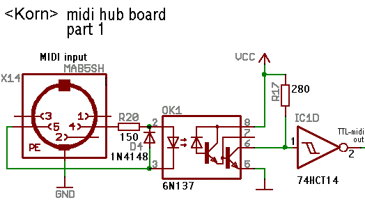
One super bright 1 W blue LED was used in the first version of this robot.
It is mapped on midi note 125 and controlled by the velo/hold PIC board. These
LED's should be cooled and driven with a constant current limited to 350 mA.
One of the following circuits -using cheap standard TO220 regulators- was to
be used in this robot:
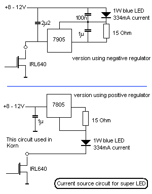
Due to -probably- a spike in the power supply, the LED circuit at some point
short after its installation gave up functioning properly and instead of just
passing away, it showed a very erratic behavior: becoming fully conductive (with
very short current spikes of far over 20 A) and opening up again. This caused
such heavy spikes on the ground lines, that it was the origin of erratic behavior
of the PIC microcontroller. Thus we replaced the circuit with a much simpler
assembly of two times three bright blue LED's connected in series with a 301
Ohms resistor. The total current at 12 V now is only 22 mA. Voltage drop over
each of the blue LED's is 2.9 V.
Output transformer:
High precision wide frequency range MCE toroidal multitap transformer. Type
nr. MCE E217T3F; Order number: 10018709, recycled from an American military
aircraft.
Cornet details:
Builder: Melchior De Vries, Lier. The instrument was made -unfortunately, for
we have an inborn hate for just about anything military- for the belgian armee.
It is marked BS (this is short for Belgische Strijdmacht) an carries the number
K.F.F.K. 14. We have no indication as to the year of construction, but since
the tuning conforms to A=440, we suspect it was made after 1939.
References:
Beauchamp, J.W. "Analysis and Synthesis of Cornet Tones Using Nonlinear
Interharmonic Relationships". In: j-aes, volume 23, number 10, pages 778--795,
1975.
Beauchamp, J.W., "Analysis of Simultaneous Mouthpiece and Output Waveforms
of Wind Instruments" . In: j-aes, 1980, Preprint No. 1626,
Benade, Arthur .H., "Fundamentals of Musical Acoustics". Ed.: Oxford
University Press, 1976.
Fletcher, N.H. & Tarnopolsky, A. "Blowing pressure power and spectrum
in trumpet playing" In: J. Acoust. Soc. Am., volume 105, number 2, part
1, 1999.
Martin, Daniel W., "Lip vibrations in a Cornet Mouthpiece", In: J.Acoust.Soc.Am.
vol13 . 1942
National Semiconductor, LM18298 Dual Full-Bridge
Driver, datasheet. April 1992
Raes, Godfried-Willem, "Kursus Akoestiek", Ghent University College
1982/2014, Internet: http://www.logosfoundation.org/kursus/4023.html
Raes, Godfried-Willem, "Expression
control in musical automates", 1977/2023,
Smith, Bob H., "An Investigation of the Air Chamber of Horn Type Loudspeakers",
in: The Journal of the Acoustical Society of America 25, 305-312 (1953); https://doi.org/10.1121/1.1907038
Robody Pictures with <Korn>:
concert performance: