Microtonal
Musical Robot
Research project on
the development of new tools for musical expression at the University
College Ghent

School of Arts
|
|
<Klar>
a robotic microtonal and moving alto clarinet
dr.Godfried-Willem
RAES
2012
|
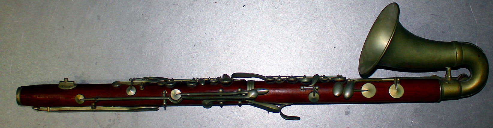
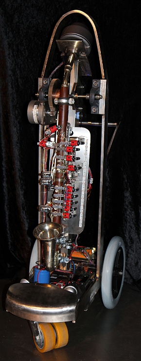
A somewhat rare instrument became the starting point of this robot: an alto
clarinet - or should we call it a tenor clarinet-, built by Higham in Manchester
in the first half of the 20th century. It's an Eb instrument, a fifth lower
than the regular Bb clarinet. and thus reaching down to G (midi 43) in absolute
pitch. So in a way it comes pretty close to the basset horn, normally in F but
reaching down to F (midi 41). In any case it's an instrument that never found
its way into the regular symphony orchestra, nor is there any classical repertoire
-at least to our knowledge- for this instrument. It has a curved metal bell and
is made -presumably- of coconut wood. The mouthpiece is connected to the instrument
through a bent neck also made of metal. The tuning conforms to A=440Hz. Here
is a picture with the neckpiece removed:
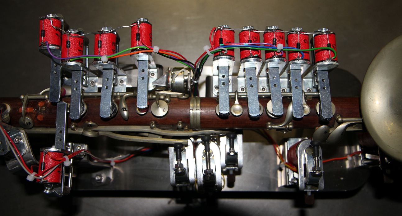
For the design we benefited from the experiences gained with previous monophonic
brass instruments such as <Korn>, <So>, <Heli>, <Bono>,
our <Autosax> -a single reed instrument-, as well as the double reed instruments
<Ob> and <Fa>. Our prime concern - next to sound production itself-
was to make the mechanical parts as quiet as possible. <Ob> and <Fa>
in that respect were the most succesful so far, but in a clarinet the forces needed
to open and close the valves are quite a bit higher than on the oboe. On the
other hand the solution that has made <Fa>, the bassoon, a success cannot
be applied here: in <Fa> we removed all existing valves and replaced them
with solenoid driven pallet valves directly mounted on the bassoon. The clarinet
body however just does not offer enough space to make that a viable solution.
Thus we had to find something in between what we realized for <Ob> and
<Fa>. Some original valves were removed and replaced by solenoid driven
valves mounted on a separate chassis. For other valves we left the original
valves and springs in place, but operated them with felt or rubber padded solenoids
replacing the human fingers.
The sound driver follows a recipe that has proven its validity over many previous
wind instrument robots: the membrane compression driver followed by a capillary
impedance convertor. Obviously the impedance convertor we finally inserted (after
having made many models on the lathe) has quite different proportions than the
ones used for the brass and double reed instruments. One of the problems was
to work out empirically the equivalent acoustical length of the clarinet mouthpiece.
There are -so far as we could find out- no mathematical models available. It
is known in acoustics that a single reed can be considered to be a flat bar
clamped at one end, but if we look at the spectrum produced once the reed is
mounted on the mouthpiece and coupled to the resonator (the clarinet proper),
almost nothing of this theory seems to hold true. What we do know is that the
pitches that can be produced on the clarinet, must be below the natural frequency
of the reed. Thus the reed is the limiting factor for the ambitus of the instrument.
As we do not have this limit in our design, we can extend the ambitus of the
clarinet way beyond what is possible on a normal instrument with a reed. Because
of the lack of an abstract mathematical model, our approach in the design of
the impedance convertor was simply musician's insight (I happen to be a former
though none too great clarinettist myself...) combined with trial and error
by successive approximation.
It is not by accident that the clarinet came to join the robot orchestra much
later than all the previously realised robotic instruments. In many respects,
the clarinet poses many more implementation problems than brass or double reed
instruments, for its expressive possibilities are the widest of all wind instruments.
First of all, there is the extreme dynamic range: a clarinet can really play
ppp as well as being capable of producing a hefty fff. That's close to 110dB,
well above what is reachable with 16 bit dsPIC or other similar processors.
Furthermore, through reed control, the timbre of the sound is modulated continuously.
This called for a pretty complex compression driver with many parameters, leading
to a wealth of controllers for the user. Then of course, there are the 'special'
playing techniques such as vibrato, flatterzunge (fluttertongue, a form of chopped
amplitude modulation), multiphonics of different kinds as well as quartertones
and microtonal inflections. Because of these complexities, we called in the
services of a true 32-bit ARM processor. The firmware models the drive of an
acoustic clarinet, including the spectral duodecime component and its slight
detuning (or shifting phase), a formant filter with resonance, as well as the
typical reed noise.
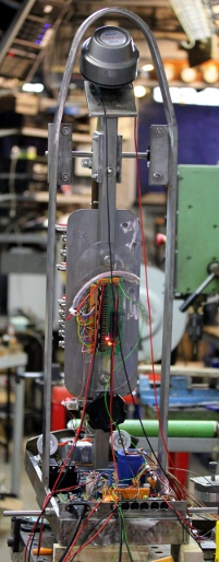
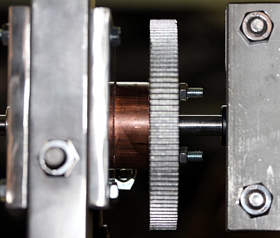
As in some previous robotic wind instruments, here again we implemented some
form of movement: the clarinet together with the valve chassis are suspended
in a cradle and can perform pendulum-like movement. The mechanism is controlled
by two dented wheels (gear ratio 1:6) and a heavy duty stepping motor. The position
of the instrument is read by a tilt sensor mounted on the vertical backbone.
By design we made sure the motor and the mechanism would not produce enough
torque to turn the instrument round fully, as this would be detrimental to the
wiring. A selection of built-in lights in different colors (white, blue and
red) have found a place in the instrument as well.
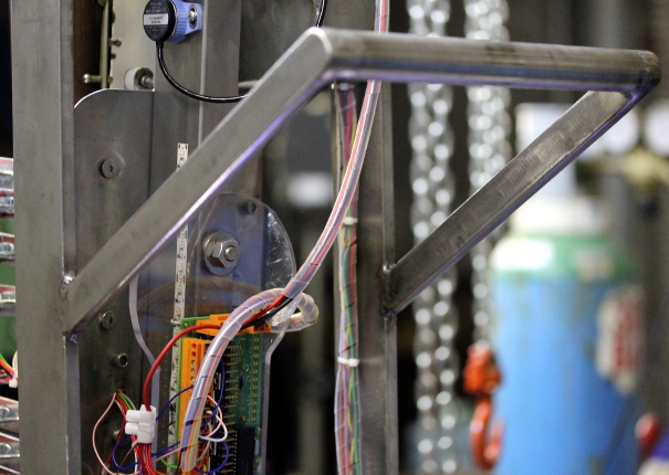
An overview of the circuitry is shown in the drawing below:
The electronic circuitry consists of four PC-boards:
1. Midi-hub board: This board, using a Microchip 18F2525 controller, takes
care of the Midi I/O handling and communication as well as the control of some
of the the lights and the movement. It also reads the tilt sensor mounted on
the moving instrument chassis.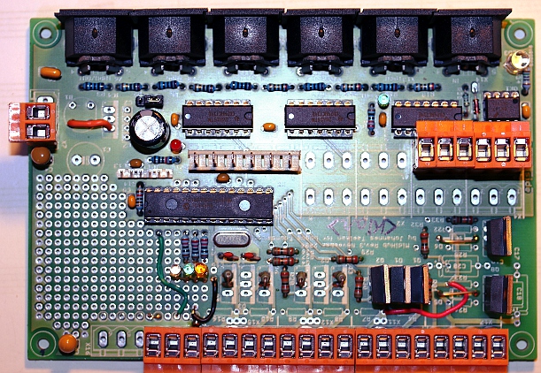
2. Stepping motor driver board using a IB106 motor controller getting all control
signals from the processor on the hub board.
3. Valve control board (Microchip 18F4620 controller). This board is mounted
on the back of the moving instrument part.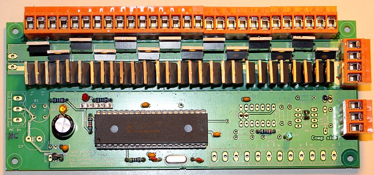
4. Compression motor driver board:
Here we used a development kit for a 32-bit ARM processor. The processor used
on the board is a STM32F407.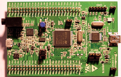 The board can be programmed through its USB connector. It even has a tiny MEMS
microphone on board.
The board can be programmed through its USB connector. It even has a tiny MEMS
microphone on board.
Power supply voltages and currents:
- +12 V dc (10 A) for the valve solenoids and the lights.
- +48V dc (2 A) for the stepping motor
- +5 V/ 1 A for processor boards
- +3.3V generated on the ARM discovery board from the 5V voltage.
- +25V/-25V - 1A (30VA) , not stabilized, for the compressor driver amplifier
Midi Mapping and implementation:
Midi channel: 5 (fixed in the firmware, offset 0)
Midi note range: 43 to 106. (Optimum sound in the range 43-91) Note on, velocity
is implemented and has a wide control range.
Note Off commands are required, but can be dropped for pure legato playing.
The note release byte, if not 0, can be used for what it's standard function
is for.
Controllers:
Controller 1: Wind controller, steers the amount of noise in the sound. Default
= 1. Advised setting: 1
Controller 2: LFO3 frequency applied to the filter. Default = 2. Advised setting:
2
Controller 3: Vibrato depth (LFO1 amplitude). Default = 20. Advised setting:
20, to turn vibrato off, set this controller to 0.
Controller 4: Vibrato speed. (LFO1 frequency). Default = 8. Advised setting:
8
Controller 5: Tremolo depth, amplitude modulation. (LFO2). Default = 0
Controller 6: Tremolo speed. (LFO2 frequency). Default = 0
Controller 7: Global volume control. Can be used for crescendo and decrescendo
effects whilst notes are sounding. This also affects the sound color of the
instrument, as normal for clarinets. Default = 80
Controller 16: Note attack speed controller (0= slow attack, 127= fast attack)
. Default setting: 100
Controller 17 is used to control the maximum sound level reached after the attack
time. This controller is always larger than or equal to the level set by the
velocity byte. For sfz or staccato playing, this controller must be set to high
levels and the velocity byte kept rather low. Default setting: 127
Controller 18 is used to control the speed of the transition between the attack
level once reached and the sustain or hold value set by the velocity byte.(0=
slow transition, 127= fast transition) default setting: 90
Controller 19: is used to control the release time after reception of a note
off. Here again a value of 0 will give a slow release whereas a value of 127
will give a very fast release. Note that with very low values, the note may
not even turn off completely. Default setting: 96. Note that if real note-off
commands are used, the release value sent with them, if this value is not zero,
will override controller 19, such that the value of controller 19 will be set
to 128-release value.
The following graph gives a picture of the mutual dependencies of all these
controllers. Note that the implementation is different than what we have implemented
in previous monophonic instruments!
Controller 20: Basic tuning of the instrument. The range is + or - a semitone.(Defaults
to value 64 for A=440Hz)
Controller 21: minimum motor speed controller (for development
only) (default = 64)
Controller 21: Motor speed. Default setting 64, corresponding to a 42 Hz stepping
rate. Set to 127, the stepping frequency becomes 64 Hz.
Controller 22: Vertical inclination controller. (0-63= backwards, 64=central,
unpowered, 65-127= forwards). At extreme positions the holding power of the motor
will not be high enough to hold the clarinet in place and as a result, the instrument
will oscillate. (default = 64)
Controller 24: 0 = motor in half step mode, any other value: motor in full
step mode (for development only. Default = 0)
Controller 25: Filter cut off frequency. Default = 62.
Controller 26: Filter resonance amount. Default = 90.
Controller 27: Echo mix. Default = 0. Only use this for experimental sounds,
as it can generate multiphonics.
Controller 28: echo feedback. Default = 0. Only use this for experimental sounds,
as it can generate multiphonics.
Controller 29: LFO3, filter depth. Default = 20. (large values give a wha-wha
effect)
Controller 30: Valve release time out.(only used for code development)
Controller 31: Does the same thing as aftertouch: fingered vibrato. However,
it does not require to be sent again and again in a sequencer. The parameter
sets the fingered vibrato speed. Default = 0
Controller 40: Bendrange for the pitchbend. 0= no bending, 1=+/- 50 cents.
Default = 1.
Controller 41: Duodecime component detune. Herewith we can detune the duodecime
partial just a bit. This causes slow beats in the sound. With setting = 64, there
are no beats. Default setting: 62
Controller 42: Duodecime component amplitude. Default = 120.
Controller 43: Wait time for vibrato start after reception of a note-on command.
Note that in legato playing, vibrato will continue. The wait time starts again
after a note off is received. Default = 100.
Controller 44: Wait time for the tremolo (AM modulation) to start after a note-on
command. Default = 10
Controller 66: Power on/off switch (0 = off, any other value is on). Power off,
resets all controllers to their cold-boot values.
Controller 100: special fingerings , bit settings for valves 1 to 7
Controller 101: special fingerings, bit settings for valves 8 to 14
Controller 102: special fingerings, bit settings for valves 15 to 21
Controller 123: switches the sounding note off, unpowers the stepper motor, dims
all the lights. Does not reset any controllers.
Program change: not implemented so far. Will be used
later for interactive robotic modes of functioning, exploiting the audio input
possibilities on the ARM-board.
Lights: The lights are mapped on very high midi-notes as follows:
- note 127: nc
- note 126: frontal red LED strip light (on/off) [F#10]
- note 125: blue LED strip light on the backside, left (on/off) [F10]
- note 124: blue LED strip light on the backside, right (on/off) [E10]
- note 123: tungsten white (halogen) upwards under the
front of the instrument., This light is dimmable. The velo byte steers the
brightness. Flashing is implemented but requires the use of the note-pressure
command after the note on. [Eb10]
- note 122: white LED strip in the front, dimmable.
The velo byte steers the brightness. Flashing is implemented but required
the use of the note-pressure command after the note on. [D10]
- note 121:frontal blue (the velo byte steers the flashing
speed, with 127 it is always ON) [C#10]
- note 120: frontal blue (the velo byte steers the flashing
speed, with 127 it is always ON) [C10]
Channel Aftertouch: used for implementing fingered vibrato. The parameter sets
the vibrato speed. Note that timbral vibrato cannot be consistently applied
to all notes! For note 43 for instance, all valves are closed and there is simply
no valve to use for vibrato. In this case we activate the overblow valve as
vibrato valve. Sending the fingered vibrato command is harmless at any time.
If it is impossible, nothing will happen. The parameter sets the speed wherewith
the vibrato is performed. Note that most sequencers reset the channel aftertouch
after every note off. To overcome that problem, we have implemented controller
31 as an alternative.
Pitch bend: The robot can be used in any tuning system. In the drawing below
we give the coding example for a quartertone scale on <Korn>, since the
implementation is similar:
 Most good sequencer
software (such as Cakewalk or Sonar) use the signed 14 bit format. Note that
one unit of the msb corresponds exactly to a 50/64 cent interval. To convert
fractional midi to the msb only pitchbend to apply follow following procedure:
if the fractional part is <= 0.5 then msb= 63 + (FRAC(note) * 128), if the
fractional part is larger than 0.5, we should switch on the note + 1 and lower
the pitch with msb= (1-FRAC(note)) * 128. Note
that the pitch bend range on <Klar> can be modified with controller 40.
By default this controller sets the range to plus or minus a quartertone. By
setting this controller to higher values, large continuous glissandi become
possible. Setting this controller to zero disables pitch bending.
Most good sequencer
software (such as Cakewalk or Sonar) use the signed 14 bit format. Note that
one unit of the msb corresponds exactly to a 50/64 cent interval. To convert
fractional midi to the msb only pitchbend to apply follow following procedure:
if the fractional part is <= 0.5 then msb= 63 + (FRAC(note) * 128), if the
fractional part is larger than 0.5, we should switch on the note + 1 and lower
the pitch with msb= (1-FRAC(note)) * 128. Note
that the pitch bend range on <Klar> can be modified with controller 40.
By default this controller sets the range to plus or minus a quartertone. By
setting this controller to higher values, large continuous glissandi become
possible. Setting this controller to zero disables pitch bending.
Classified by function, we have the following groups of controllers:
- Note Off, with release byte implemented
- Note On: ADSR: CC16,17,18,19, velocity byte
- Tuning related controllers: CC20, pitchbend, CC40, CC41
- Vibrato: CC3, CC4, CC31, CC43
- Tremolo: CC5, CC6, CC44 (can also be used to implement Flatterzunge effects)
- Sound color: CC2, CC25, CC26, CC29, CC42
- Movement: CC21, CC22, CC24
Download the complete midi implementation for
<Klar> in a synoptic and easy to print format (odt file).
Technical specifications:
- size: l= 670 x w= 300 x h=1200 [flightcase: l = 690 x w = 425 x h = 1235]
- weight: 56 kg [ flightcase: 30kg]
- transportation: needs its flightcase. The moving part should be blocked
during transportation, such that the instrument can be reclined. There is
a special piece available to do this.
- Power: 230 V ac / 120 W (measured, playing)
- Note: on cold boot it is mandatory that the robot is positioned in its vertical
rest position and that it is mechanically free to move.
- Tuning: based on A = 440 Hz (within 1 cent). The tuning can be adjusted.
- Ambitus: 43 - 106 (real pitch)
- control: MIDI-input, 5 MIDI-Thru, Optional: 1 MIDI-Out, if used there are
only 4 midi thru outputs. (UDP port to be implemented later)
- Insurance value: 16.500 Euro (with case)
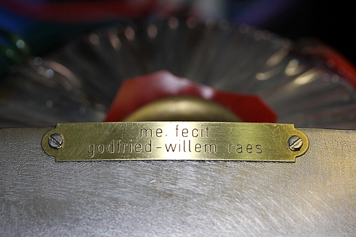
Design and construction: dr.Godfried-Willem
Raes
Collaborators on the construction of this robot:
- Kristof Lauwers (GMT player implementation)
- Johannes Taelman (ARM chip firmware)
- Mattias Parent (Flightcase construction)
Music composed for <Klar>:
Classical pieces adapted for <Klar> and the robotorchestra:
- Robert Schumann "Romanzen"
- Claude Debussy 'Premiere Rhapsody'
- Rimsky-Korsakov 'Clarinet Concerto'
- Aaron Copeland 'Clarinet Concerto'
- Germaine Tailleferre 'Arabesque'
Final evaluation of the <Klar> experiment:
The robot can be controlled such as to perform classical pieces
(Debussy's 'Premiere Rhapsody' is a good example) in a quite convincing way.
However, realizing this, involves a lot of work from the side of the programmer,
since all details with regard to expression have to be translated into appropriate
controller commands. Seen in the group of monophonic wind instruments designed
and build sofar, <Klar> is doubtless the most flexible instrument. The
wealth of controllers make it possible to program the instrument such as to
sound sounds completely unlike what we expect clarinets to be capable of doing.
It can easily surpass the possibilities of human players but at the other hand,
human players can produce sounds that this robot is not yet capable of producing,
such as some multiphonics, loud slaptongues and vocal-instrumental interfering
sounds.
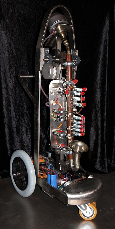
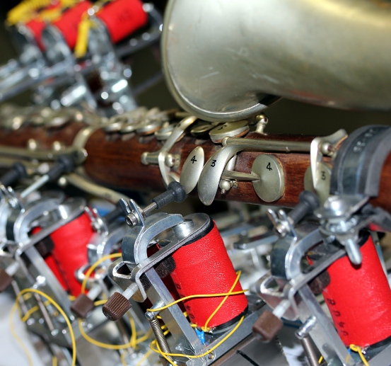
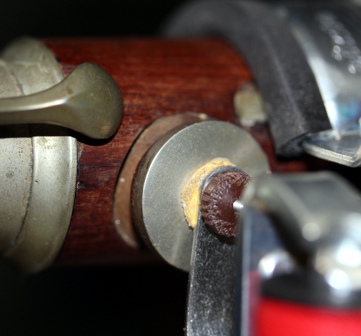
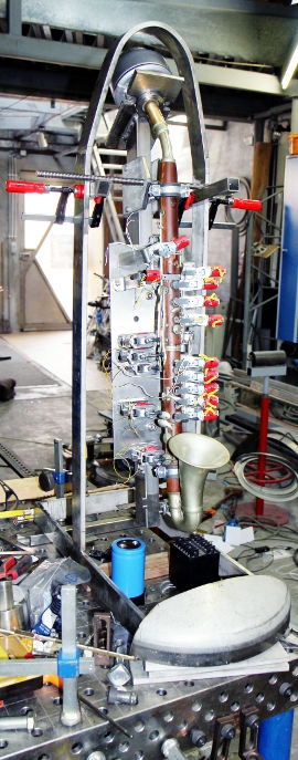
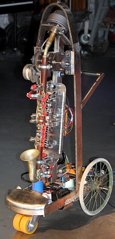
Pictures taken during construction in our workshop:


Nederlands:
<Klar>
Er is voorlopig geen nederlandse tekst beschikbaar.
Construction & Research Diary:
- 1984: Purchase of the alto clarinet. A crack in the upper part repaired.
Fine tuning of the mechanical parts and the valve seatings. With this acquisition
we now have a collection of old Albert-system clarinets in the following tunings:
High E, Eb, D (early 19th century), C (in metal), Bb-452Hz (Mahillon), Bb-440Hz,
Bb-435Hz, G, Eb (Higham) , Bb-bass (Buffet-Crampon). Still looking for a very
high Ab as well as a contrabass clarinet.
- 12.08.2010: first drawings towards automation. First designs for a capilary
driver with a reed-like cut up in the mouthpiece driver.
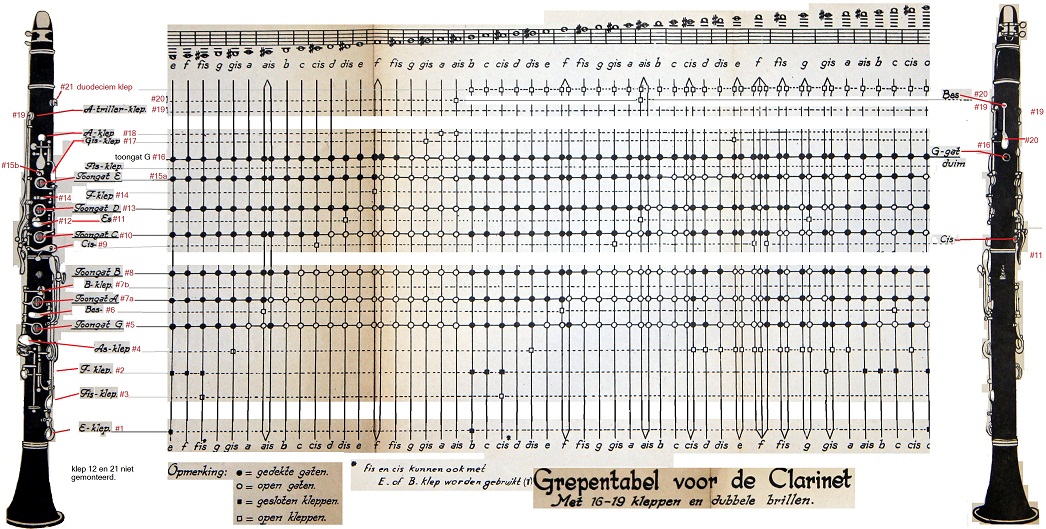
- 20.12.2011: Precise determination of the instrument: tuning check, fingering
table. Pretty much an Albert system it is.
04.04.2012: first experiments with the sound generator devices: horn motor
compressors. We might be able to use our wave generating circuit as developed
for the <Synchrochord>, using an Intel 8254 timer. As an alternative
an ARM processor would also be possible but might take a much longer development
time.
- 08.07.2012: First model of an acoustical impedance convertor with capillary
driver turned on the lathe from a piece of brass. Attempt to mimic the effect
of the single reed mouthpiece cavity.
- 12.07.2012: In between the many rehearsal sessions for the Namuda production,
we even found the time to turn an alternative impedance convertor on the lathe.
Now we can evaluate which one performs best and orient the research accordingly.
- 15.07.2012: Cutting out of the carrier plate for the compressor driver from
10mm thick stainless steel. Plate sizing: 100x180x10.
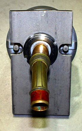
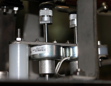
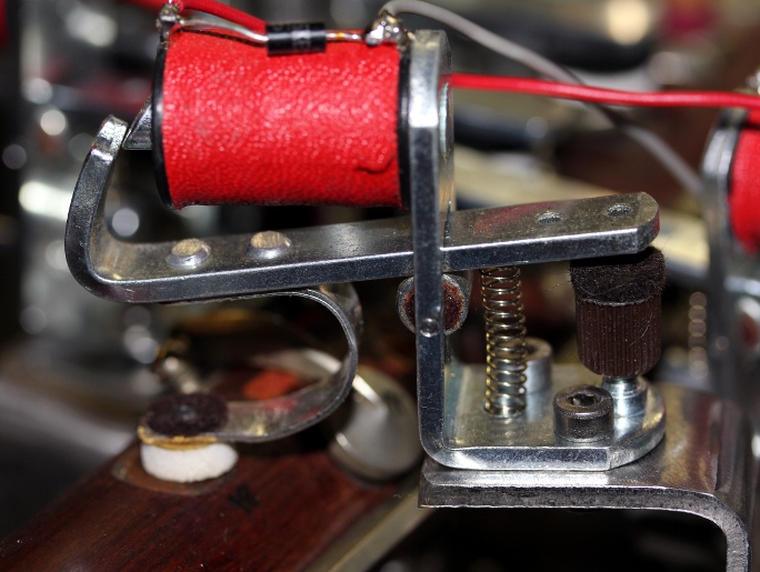
- 25.07.2012: Discussing the design with Johannes Taelman. Here are some picture
of the compression driver assembly:
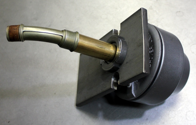 The bent piece is from the original instrument. .
Mounted together it now looks like this:
The bent piece is from the original instrument. .
Mounted together it now looks like this: 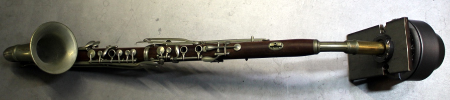
- 11.08.2012: Welding works on the vertical column to hold all mechanical
moving parts. This is a piece of 50x30x2 stainless steel profile. I was a
bit handicapped by Moniek's small dog Floesj, who insisted on always being
very close to me, even whilst welding. That's very dangerous for him, so I
had to prevent it all the time... There are no welding helmets for dogs as
far as I know.
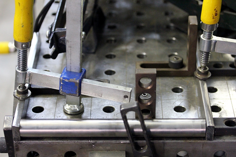
- 12.08.2012: First mounting of the instrument on the welded chassis using
two Sikla clamps with an M10 thread and a rubber inlay. To do this it was
required to remove the duodecime overblow valve #21 (which in any case we
would not need here) as well as the attachment for the music stand on the
upper part. On the low side, both levers for the lowest notes (#1 and #2)
had to be removed to make space for the clamps. Working out the fingering
table. 19 or 20 solenoids will be enough, it seems. There will be different
functions, as we will implement push for close as well as push for open types.
Trying to avoid tubular solenoids, as they would have to operate on a horizontal
plane.
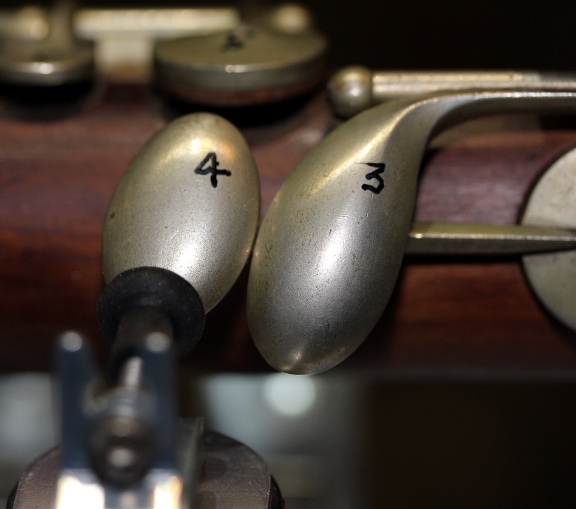
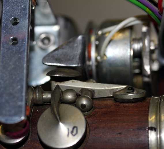
- 13.08.2012: Threaded rod M10 in stainless steel bought from MEA. Study of
motorized movement requirements. Design of possible wheelbases. Valves numbered
for ease of implementation:
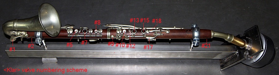
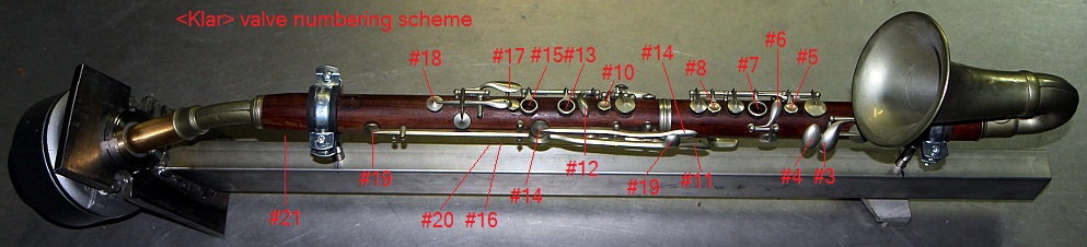 Valves 21,20 and
16 are on the underside, normally operated by the left thumb. Valve #16 is
the thumbhole. Valve #21 is only for second overblowing and we might not need
to implement this one. On this clarinet we can use valve #20 for playing Bb,
whereas on common instruments with the Albert fingering system, this note
requires the overblow valve. In fact the alto clarinet uses #20 as well as
#21 as overblow valves, just like on the bass clarinet.
Valves 21,20 and
16 are on the underside, normally operated by the left thumb. Valve #16 is
the thumbhole. Valve #21 is only for second overblowing and we might not need
to implement this one. On this clarinet we can use valve #20 for playing Bb,
whereas on common instruments with the Albert fingering system, this note
requires the overblow valve. In fact the alto clarinet uses #20 as well as
#21 as overblow valves, just like on the bass clarinet.
- 14.08.2012: Thumbrest and neck strapholder removed from the back of the
instrument. Fingerplate for valve #19 sawn off. Solenoid for valve #11 mounted.
This makes it unnecessary to automate valve #12, as it serves the same function.
- 15.08.2012: Mounting works solenoids for the valves. Valves #1 and #2 on
the low side of the instrument mount with a bracket directly on the vertical
column. The others ought to find a place on a horizontal plate, with studs
in height depending on the required traject and position. Valve #3 solenoid
will work on the pad directly and not on the fingerplate. Valve #4 can be
operated with a solenoid pushing on the fingerplate.
- 16.08.2012: Construction of the carrier for the two soft shift solenoid
valves we will use to operate the thumb valves underneath the instrument.
Ball bearings ordered from MEA for the movement,
- 17.08.2012: First test mount of nearly all valves on the bottom plate. Solution
found for the problem of valve #9: we will use a small rotary solenoid here.
Note that valve #18 is closed at rest, but when pressed, it also close the
bridge for toneholes #15 and #13 (spectacles). These open holes operate valve
#15b, covered under a flat plate. Thus we added a solenoid to operate this
valve separately. Spoke wheels ordered from Kaiser and Kraft.
- 18.08.2012: first rough adjustment session of the valves. Preliminary wiring.
Design of the cradle and the movement mechanics. Weight of the moving part:
12kg. Point of gravity and equilibrium determined. This is required for the
design of the movement mechanics. We plan to use dented wheels to make gears
and a large size stepping motor. Preliminary pictures posted on Facebook.
M5 panhead screws turned on the lathe to make a precise fit for the rubber
fingers activating the valves on the left side of the clarinet. Valves #3,
#4, #11, #14 and #19 are adjusted now. Valve #1 (on the bell) mounted and
adjusted.
- 19.08.2012: Bending works with the Ridgid pump on 10mm thick stainless steel.
Couldn't do it with that alone, so the acetylene torch had to come to rescue.
Would anyone believe it took us almost all day to get this U-shape bend right?
After our calculations, the stepping motor we will use is not powerful enough
to fully lift (and hold) the clarinet assembly to a 90 degree position. This
is intended by design, avoiding a potential disaster if the assembly were
allowed to turn around. Pendulum movements with large amplitudes will be well
within the possible.
- 20.08.2012: Tilt sensor (Penny & Giles) ordered from Farnell, as well
as some 2x18V / 30VA toroidal transformers. Spoke wheels ordered from Kaiser
& Kraft. Mounting plate for the double frontwheel cut out and drilled
from 100 x 10 x 240 stainless steel. Mounting holes: M10. Sizing of trolley
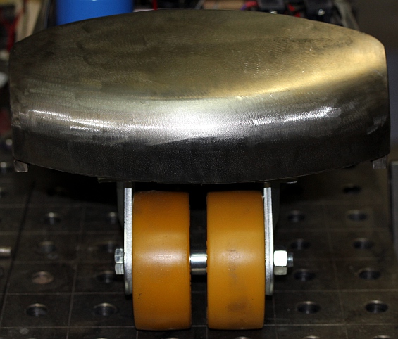
decided:
 The
back wheels are 300 mm in diameter. The front wheels make turns possible and
use yellow polyurethane tires.
The
back wheels are 300 mm in diameter. The front wheels make turns possible and
use yellow polyurethane tires.
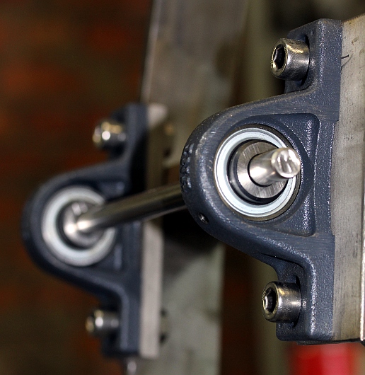
- 21.08.2012: Flange bearings and holders delivered from MEA (art. nr. LAG135029258
[flenslager GYE 12 KRRB] and LAG135029142 [Blok GG-ASE03]). Cost 43 Euro.
Toroidal transformers delivered from Farnell. Calculation of 12V power supply
needs: We have 5 valves with 32 Ohm resistance, thus demanding 375mA each
= 1.875A. There are 13 valves with 82 Ohms, thus 13 x 150mA = 1.95A, two softshift
solenoids at 29 Ohm = 2 x 414mA = 0.83 A and a single rotary solenoid with
30 Ohm resistance, demanding 400mA. Thus theoretical maximum required current
(with all solenoids active at once) would be 5 Amps. So with a transformer
rated for 100VA we should have enough power. Dug up a 150VA toroidal, formerly
used for halogen lighting. This one mounts nicely under the frontal hood,
just above the wheels. Power supply circuits drawn out:
 Drilling of all required holes in the already cut out parts that have to be
welded together later on. Mounting plate for the midi-hub board, the mains
power entry, the on/off switch, the 2x18V toroidal transformer cut out and
drilled. Mounting bar made for the 5V power supply module. Holes for the wheel
axis drilled (12mm). We cut, drill grind and polish all parts before performing
any welding. We learned our lesson from previous similar projects where it
became nearly impossible to drill the required mounting holes on the already
welded together parts...
Drilling of all required holes in the already cut out parts that have to be
welded together later on. Mounting plate for the midi-hub board, the mains
power entry, the on/off switch, the 2x18V toroidal transformer cut out and
drilled. Mounting bar made for the 5V power supply module. Holes for the wheel
axis drilled (12mm). We cut, drill grind and polish all parts before performing
any welding. We learned our lesson from previous similar projects where it
became nearly impossible to drill the required mounting holes on the already
welded together parts...
- 22.08.2012: Mounting of the Erea 100VA 48V transformer powering the stepping
motor and the IB106 driver.
- 23.08.2012: Welding works. Finalisation of the chassis.
 Test mounting of components.
On the picture we brought together most of the components to be mounted on
the chassis:
Test mounting of components.
On the picture we brought together most of the components to be mounted on
the chassis: . Placed
on the welding table, and temporarily fixed just to test sizings and movement
freedom, it now looks like:
A first fitting for a 3W LED light mounted on the recifier and elco chassispart.
Color should be yellow or white...
. Placed
on the welding table, and temporarily fixed just to test sizings and movement
freedom, it now looks like:
A first fitting for a 3W LED light mounted on the recifier and elco chassispart.
Color should be yellow or white...
- 24.08.2012: Design of the mixer circuit for external drive input. There
will be two potentiometers for volume control. External feed via a 1/4"
jack (balanced or unbalanced), internal drive via Cinch RCA connector. Bottom
plate for mounting of amplifier, motor controller and waveform generator cut
out (3mm thick), drilled and welded in place. The two potentiometers and input
connectors mount on a piece of Z-shape bend stainless steel, a left over from
the <Spiro> construction. We used two 6k8 wirewound potmeters (in nature
linear) because of their high quality. Log would obviously have been a better
choice. We took the resistance pretty low, to minimize the risk of hum interference.
It had to be lower in any case than the 100k input impedance specified for
the HY2001 amplifier module. We made a passive mixer, just to avoid having
to add symmetric power supplies for a single op-amp. Of course we could have
used a single supply opamp, but powering it from the same supply as the solenoids
is very bad design practice. Although
we do not have the PC board for the waveform generator as yet, we provided
a maximum physical size for it of 160 x 100 mm (Eurocard size). That should
be more than enough for even a maximalistic modern design, including analog
formant filters.
- 25.08.2012: Mixer circuit soldered and mounted in place. Amplifier mounting
and wiring done, including the mounting of the toroidal transformer underneath.
All power wiring on mains voltage finished, including the switch. Definitive
mounting of the 250W frontal toroidal transformer (M10 bolt, mounted with
Loctite) for the 12V supply. Rectifier
bridges mounted and wired from transformers as well as towards the large electrolytic
capacitors. Voltages tested o.k. Curved frontal piece cut out and welded in
place. This piece needs a high polish for a good finish. We
might find some space for lights under this frontal hood. Started soldering
of the midi-bub board, pretty much modelled after the same board in <Ob>
and <Fa>. Circuit drawings added to the technical spec list at the end
of this page.
- 26.08.2012: Continuing of soldering work on the midihub board. Its finished
now. The firmware design for this one can take off.
Ball bearings for the suspended part dod-welded in place:
Construction of the front lights. We wanted to use yellow, but didn't have
that in stock, so for now these colors will be blue... Start coding of the
firmware for the hub board.
- 27.08.2012: Code development of firmware for the hub board. We cannot test
it since neither the sensor nor the dented wheel have flown in yet... Start
definitive wiring of solenoid valves on the instrument. Start soldering of
all components on the valve solenoid board. Construction of the carrier plate
from polycarbonate. This carrier board mounts on the backside of the instrument.
- 28.08.2012: Valve board assembled and tested. PC board mounted on the carrier
plate. Start coding firmware for the valve controls. Herefore we can start
off with the code model developed for our <Fa> robot. Valve seats adjusted
and pads made anew where missing. First version of a complete fingering table
assembled.
- 29.08.2012: Further work on the fingering tables. Calculation of all required
portsettings for the PIC firmware.
- 30.08.2012: Research on fingering tables. A very good source of information
on quite a lot of different fingering tables can be found at: http://www.wfg.woodwind.org/clarinet/index.html.
There are tables for Boehm, Oehler and Albert system clarinets as well as
for multiphonics and quartertones. Finalisation of the wiring of the valve
solenoids. Only the rotary valve still needs some more work now.
- 31.08.2012: Wiring of the Weidmueller connectors on the valve board. Bending
work done on the rotary valve for C#. Further work on the encoding of the
fingerings for the firmware.
- 01.09.2012: Coding of the lookup-tables in the firmware for the finger-PIC
controller. We still have to figure out the lookup table for the valves to
use for fingered vibrato. The implementation will be similar to what we did
in our <Fa> robot. Working session with Johannes Taelman on the microcode
firmware for an ARM processor to drive the compression motor. Should become
better than previous implementations using the dsPIC's. We are using a development
kit as these are a lot less expensive than any imaginable board designed by
us.
- 02.09.2012: Mounting of the ARM processor board on a eurocard sized PC board
accomodating the required connectors. The midi in signal must be reduced to
3.3V TTL levels, hence the passive voltage divider network with a 240 Ohms
resistor in series and a 470 Ohms over the serial input on the ARM board pin
PD9. We power the board from the +5V supply, as it has its own 3V3 voltage
regulator on board. Start implementation of <Klar> in GMT. <Klar>
plays its very first notes... however, there still is a bug in the valve firmware
or its wiring.
- 03.09.2012: Wiring bug located and killed. The valve firmware does work.
We still have to figure out optimum valves to use for the fingered vibrato.
Furthermore, the softshift solenoids will need a series resistor since they
tend to get too hot. The ARM code needs a lot of work still: all notes off
needs to be implemented, as well as CC60 for on /off with a reset of all controllers
to their default start-up values. Pitchshift must be reduced to -64 to + 63
cents instead of a semitone.Looks now, on the welding table with missing wheels
and motor gears:
We decided to use
6V bulbs instead of resistors to limit the current through the softshift solenoids.
Different kinds of E10-fitting 6V bulbs ordered from Farnell. The bulbs will
work here as voltage controlled resistors.
- 04.09.2012: Further measurements on the performance of the softshift solenoids.
Idea to give <Klar> some interactive build-in robotic features: Since
it has a microphone on board, it could be made to listen to the environment
and react to it. During the playing, the listening function ought to be switched
off. Program change command could be used to select different robotic modes.
Lookup table for fingered vibrato for notes 43 up to 69 determined and input
into the firmware lookup table for the valve board. Tested o.k. Still waiting
for the delivery of the dented wheels as well as the tired wheels.
- 05.09.2012: Lights implemented with bit-masks in the firmware of the valve
controller board. Design of the stepping motor mechanics. The dented wheels
as well as the Penny & Giles tilt sensor came flowing in today, so this
part of the motor movement firmware can be checked out after mounting of the
sensor and the other mechanical parts. Design and construction of the mounting
parts for the dented wheel on the clarinet holding structure. We decided to
use a piece of 20mm thick, 50mm diameter red copper as a cushion and distance
holder. Mounting with M6 bolts in stainless steel. The motor mount poses some
particular problems. Placing it on the back of the robot appears to be impossible,
so we decided to mount in frontally.
- 06.09.2012: Motor wiring finished. Sensor mounted with a parker screw and
position secured by applying a thin layer of silicone glue. Signature copper
plate mounted... LED-light strips mounted on the moving part, red and blue.
E10 bulb socket mounted on the front side. This will be switched in series
with the thumb softshift solenoid. We intend a 6V 4.2W halogen bulb to be
placed here, functioning as a voltage dependent resitor. <Klar> is getting
ready, at least all the hardware for it.
Work on the motor steering firmware. After the welding works on the motor
holder and reconnecting all wires, it seems that our ARM board has given up.
Apparently it doesn't like welding works in its neighbourhood, even though
it was not switched on! Could it be the exposure to very strong UV?
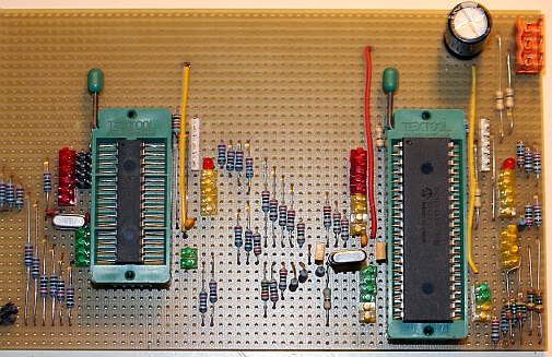
- 07.09.2012: Expansion of my programming board made last year for the 40pin
PIC processors, with a textool socket for 28pin devices. This makes debugging
a lot more comfortable.
 Continuing
development of the motor code on the midi hub board. Hysterisch added in coding,
for the equilibrium position is in fact a range of values rather than a single
crisp one. Now at least on initialisation, it does not start oscillating anymore.
Motor gear wheel secured to shaft by drilling a small 3mm hole. This was very
difficult since we did not remove the motor for this operation. With the defunct
ARM discovery board, Klar remains silent for the time being. The movement
functionality is coming close to finalisation now.
Continuing
development of the motor code on the midi hub board. Hysterisch added in coding,
for the equilibrium position is in fact a range of values rather than a single
crisp one. Now at least on initialisation, it does not start oscillating anymore.
Motor gear wheel secured to shaft by drilling a small 3mm hole. This was very
difficult since we did not remove the motor for this operation. With the defunct
ARM discovery board, Klar remains silent for the time being. The movement
functionality is coming close to finalisation now.
- 08.09.2012: Further refinement of motor coding, after solving some minor
mechanical issues requiring filing... Worksession with Johannes Taelman on
ARM-coding and controller assignment. We also made a replacement back-up board.
We implemented a wealth of controllers, mostly for research purposes. Midi
implementation updated according to the newest firmware version. Klar sounds
again.
- 09.09.2012: Writing of test code in GMT for all the controllers implemented
sofar. This allowed us to compile a parameter settings list that may serve
as a good base of departure for the users. Measurement of the sound output:
at maximum level setting we have ca. 13V rms over the 16 Ohm driver. This
means a true rms power of 10.5 Watt. This should be safe. LED white strip
added to the front, with a bolted carrier plate. Today should be considered
the day of birth of the <Klar> robot. But, as verybody knows, a baby
is not yet a fullgrown. In this case however, it can already join the M&M
robot orchestra.
- 10.09.2012: Demo of <Klar> for collaborators. Construction of the
piece required for reclined transportation of the robot.
 Design
and construction of a steering handle.
On the picture you can see the components in stainless steel swan out and
mounted on the welding table ready for being welded. Here is the result, after
welding and mounting on the robot: This
time we took many precautions to make sure the ARM processor board would survive
the welding operations in its neighourbood. With success: it did survive the
operations this time ! Still waiting for delivery of the spoke wheels...
Design
and construction of a steering handle.
On the picture you can see the components in stainless steel swan out and
mounted on the welding table ready for being welded. Here is the result, after
welding and mounting on the robot: This
time we took many precautions to make sure the ARM processor board would survive
the welding operations in its neighourbood. With success: it did survive the
operations this time ! Still waiting for delivery of the spoke wheels...
- 11.09.2012: To make integration in the orchestra possible, we adapted some
old and worn wheels to fit <Klar>.
 These
wheels are about 2 cm too large, such that the robot leans a bit too much
frontal...
These
wheels are about 2 cm too large, such that the robot leans a bit too much
frontal...
- 13.09.2012: Protective cap over the mains switch and the chassis part of
the 3-prong connector made. This to reduce risk of electrocution for the users.
Note that the instrument itself is grounded to mains earth. None of the power
supplies however make a connection with the chassis parts. Only at the audio
amplier input there is a connection to the chassis.
- 14.09.2012: Shouldn't we prepare a PIC-radar driven demo for Klar, as it
is supposed to be presented to the large public on the Ghent culture market
tomorrow... Bug discovered in ARM-firmware: note on with velo 0 does not switch
off the sounding note. Bug fixed with an emergency call-in to Johannes Taelman.
One more bug: for some reason the fingering PIC seems to fail under circumstances.
PIC reprogrammed with some minor changes in the firmware....
- 15.09.2012: <Klar> makes his first trip: up to the culture market
on saturday afternoon... with Xavier Verhelst, Moniek Darge and Sebastian
Bradt. This is the first public presentation of the new robot.
- 16.09.2012: Coding test for <Klar>'s first gesture controlled composition,
Namuda study #26: 'Ritual'. Rehearsal with Dominica Eyckmans. Some 'Robody'
pictures shot and added at the very end of this webpage. Scroll down to see
them. Polishing works on the metal parts of the clarinet. It now shines.
- 17.09.2012: Some minor bugs revealed: PWM on the lights seems to cause trouble
with valves clicking and blue lites triggering. Check hardware, check firmware.
Here we could raise the PWM frequency. Motor speed can be increased a bit.
Current resistor on IB106 changed to 240 Ohms. Measured voltage over the power
supply under maximum load: 57V, current: max. 2A. Over the 240 Ohm resistor
we have 310mV. Seems we can still safely increase the resistance value.
- 19.09.2012: The definitive wheels came flowing in and we mounted them right
away. Now the rest position of Klar is horizontal.
- 23.09.2012: <Klar> made his debut performance in Antwerp on Time Canvas
in the M HKA with the premiere of 'Slones'.
- 01-15.10.2012: Research to find the best acoustical model for the driver
waveform. This code is developped within our <GMT> code project on the
Wintel platform. Once we get the algorithms right, they should be translated
to the ARM-platform.
- 19.10.2012: Smoke stack from the overvoltage protecting varistor for valve
8, resulting in a burn-out of mosfet nr.9 on the valve board... The copper
on the board on the output of the MOSFET was completely burned away. Apparently
these varistors cause a strong short when they conduct or fail... No idea
as to why this component failed here. This kind of failure never happened
on any of my robots sofar. Maybe we should remove all varistors, as we have
protecting diodes on the boards already. Repair performed: board and Mosfet
repaired.
- 20.10.2012: The blue frontal LED spotlite, mapped on note 121 seems also
have gone to heaven. LED spot gone, mosfet on the hub board gone as well.
Could something cause high spikes on the 12-17V supply voltage? Did we forget
a diode somewhere? Solenoid traject for valve #11 adjusted. It was not fully
closing at rest.
- 21.10.2012: Klar did a very nice job in the conservatory concert devoted
to my work this afternoon. No failures whatsever.
- 25.11.2012: Klar presented on the 'Day of Science', Balzaal at Vooruit.
Organized by Ugent and Hogent - School of Arts.
- 06.04.2013: Bell mounted on clarinet body using Loctite brown silicon. It
had a tendency to slip off during movement. Valve spring for valve #4 repaired,
as it didn't return anymore.
- 20.04.2013: <Klar> survived the trip to Glasgow very well! We expect
her back in Ghent on monday 22nd of april. Considering to build a complete
flightcase however...
- 23.04.2013: No failures on return of <Klar>. Nevertheless we decided
to design a flightcase.
- 26-28.09.2013: <Klar> presented at the BEAF (Brussels Electronic Arts
Festival), together with <Horny>, two robots using the Axo platform
to some extend.
- 29.09.2013: <Klar> returned safely from BEAF Brussels and took up
its place again in the robot orchestra.
- 18.07.2014: Article on <Klar> submitted on request to No Patent Pending,
a dutch iii publication.
- 19.10.2015: Check-up on Klar after its appearance at and transportation
to the Dok19 concert. Everything seems o.k.
- 26.09.2016: <Klar> transported to Berlin for participation in the
'Wir sind die Roboter' Festival.
- 02.10.2016: After transportation to Berlin and back, some of the nuts holding
the softshift solenoids on the backside of the instruments got loose. One
nut lost. It's an UNC thread (#3-48 UNC-2A)
so we will have to dig up a replacement nut.
- 03.10.2016: Fixes performed. nuts fixed with Loctite7000 (red varnish).
<Klar> found to be in perfect working condition again. Movement also
checked and found o.k. A flightcase for <Klar> is really required...
- 06.10.2016: Start construction of a flightcase for <Klar>. Cutting
of L-profiles, stainless steel, 30 x 30 x 3 under 45 degree angles.
- 12.10.2016: All panels for the flightcase sawn.
- 13.10.2016: Flightcase for <Klar> almost finished. Waiting for the
Parabond kit to bind off.
- 14.10.2016: Flightcase finished and labeled for <Klar>. It can go
on the road safely.
- 18.10.2016: Blocks mounted inside the flightcase, such that it can be transported
in a reclined position as well as vertical.
- 28.10.2016: <Klar> taken on the road to Brugge for 'Iedereen Klassiek'
in its newly made flightcase.
- 30.10.2016: <Klar> set up again in the orchestra and found fully o.k
apart from a large electrolytic capacitor that needs to be glued to its base,
as it went loose by putting Klar flat in its case during transportation.
- 26.07.2017: Applied with pitch dependent volume scaling in our 3th Symphony
as well as in the Fall'95 version we prepared for performance in Liepaja (Latvija).
A usefull formula to calculate a normalized scaling factor to apply to the
velocity values -using the normal clarinet range 43 to 94- is: Velfactor =
0.5 + ((1 - ((midinote - 43) / 51)) / 2 ).
- 02.08.2017: <Klar> on the road to Liepaja.
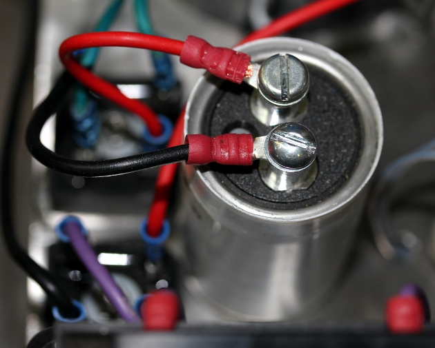
- 04.08.2017: The large electrolytic capacitor came loose from its holder
during transportation with its lightcase flat. Fixed for the concert, but
on return in Ghent we will have to glue it in its holder with some silicon
compound. <Klar> worked fine in the concert in Liepaja and in the setup
under radar control.
- 09.08.2017: <Klar> returned safely from Liepaja (Letland).
- 22.11.2017: <Klar> joined the party at euRobotics and found o.k. on
its return into the orchestra.
- 13.07.2018: <Klar> joined the orchestra for the opening of the Ghent
Feasts at Sint-Jacobs.
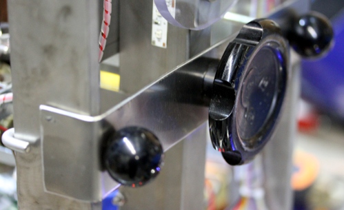
- 09.09.2018: Designing a control module to allow Klar to operate without
an external computer. This is a requirement for <Klar>'s appearance
in the robot exhibition in the Speelklok museum in Utrecht,
 The
Axo board used can hold a series of demo-files, selectable with the rotary
switch. A musical piece can start on detection of movement. This interface
can be build on a stainless steel rod mounted on the steering handle with
a clamp or else and even better, on a stand-alone microphone stand. These
are the connections on the Axoloti board:
The
Axo board used can hold a series of demo-files, selectable with the rotary
switch. A musical piece can start on detection of movement. This interface
can be build on a stainless steel rod mounted on the steering handle with
a clamp or else and even better, on a stand-alone microphone stand. These
are the connections on the Axoloti board: 
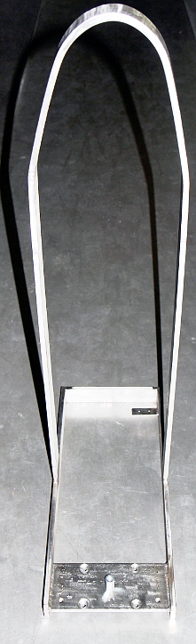
10.09.2018: Complete circuit build-up. We used an old cast aluminum shelve
loudspeaker enclosure as a starting pount for the housing. The interface uses
an external SMPS 12V power supply. This way, no mechanical nor circuit modifications
were required on <Klar> itself. Here are some pictures of the module:
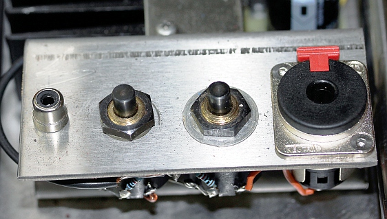
 Frontal view with
the front panel removed. The connectors on the Axoloti board are not used
here. This is the backside:
Frontal view with
the front panel removed. The connectors on the Axoloti board are not used
here. This is the backside:  There
is the rotary switch, the midi-out connector, and a connector for a 12V DC
power supply. The TO3 voltage regulator is mounted on the outside of the box
serving as a heatsink, in fact this box is a recycled loudspeaker enclosure
made in cast aluminum. The 20th century sonar intrusion alarm circuit, when
opened up looks like this:
There
is the rotary switch, the midi-out connector, and a connector for a 12V DC
power supply. The TO3 voltage regulator is mounted on the outside of the box
serving as a heatsink, in fact this box is a recycled loudspeaker enclosure
made in cast aluminum. The 20th century sonar intrusion alarm circuit, when
opened up looks like this: 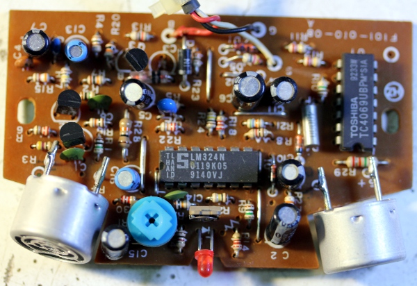 We
bought quite a few of these intruder alarms in the nineties of last century
as we needed 40kHz crystals at some point to make sharp filters for our invisible
instrument. Recycling them from these devices was cheaper than buying the
crystals separately...
We
bought quite a few of these intruder alarms in the nineties of last century
as we needed 40kHz crystals at some point to make sharp filters for our invisible
instrument. Recycling them from these devices was cheaper than buying the
crystals separately...
11.09.2018: Lara Van Wynsberghe works on the Axoloti firmware for the control
module.
- 12.09.2018: <Klar> ready for his appearance in the Speelklok museum
in Utrecht. The way it works now is that is plays the embedded files, as long
as movement is detected. On movement stop and new movement detected, it will
start all over again with the first embedded file.
- 13.09.2018: Klar left of to Utrecht to the Speelklok Museum. It will return
to join the orchestra again around march 2019.
- 07.03.2019: <Klar> returned safely from the Speelklok Museum in Utrecht,
where it played every day for six months.
- 30.07.2019: <Klar> returned in good shape from Tomorrowland. All tests
passed. Only the flightcase must have been left in the rain and was found
full of mud...
- 02.09.2021: Opening of the robot exhibition at the SMAK museum, including
the <Klar> robot.
- 27.09.2021: After playing uninterrupted for 25 days in the SMAK museum,
<Klar> returned to the robot orchestra in perfect condition.
- 13.10.2021: Major revision of the firmware for the hub board. This board
steers the motor for the movement as well as four lights. Code brought in-sync
with the latest version of the Proton Compiler.
- 17.10.2021: Sensor voltages checked again: equilibrium range 2.48 V to 2.56
V, center value 2.528 V. In 10 bit resolution this conforms to 508 -518 -
524. Thus the center value in still 64, if we reduce the 10-bit readings to
7 bit. The motor can hold the structure backwards up a a voltage reading of
2.33V (= 477 in 10 bits) and forwards up to 2.66 V (= 545 in 10 bits). We
can go further, but in that case, we have to cope with oscillations. Upgrade
of the firmware for the hub board, responsible for the movements, finished.
- 22.07.2023: Major check on return from the tango production on the Ghent
Feasts. Everything seems to work fine.
- 14.09.2023 - 02.10.2023: <Klar> participated with the robot orchestra
in the Zeroth Law production by Gamut Inc. at the Deutsche Oper Berlin. It
performed and returned flawless.

- TODO list:
- Circlip slots for the wheels on the lathe to be made.
- improve the timbre and make it less harsh. The formant
filter needs to track the register the instrument is playing.
- implement a low pass filter in the firmware.
- Further develop firmware for autonomous robotic interactive
operation using the features of the ARM board.
Last update: 2024-03-05
by Godfried-Willem Raes
The following information is not intended for the general public, but is essential
for maintenance and servicing of the robot.
Technical drawings, specs, maintenance
notes and data sheets:
Fingering - valve numbering schemes:
Fingering Table (separate html page)
Note: valves 11 and 12 are interchangeable. They are never used together so
we automated only one of these valves. The mechanism for valve 21 was removed
from the instrument. Originally it was placed next to the thumb hole.
Rotary solenoid: Lucas
Ledex type nr.H-1079-032 (Price: 123 Euro)
Cold resistance is 30 Ohms, thus the current drawn at 12V comes to 400mA.
Soft shift solenoids:
Lucas Ledex type nr. 70019696, P.O# 4166460, manufacturing date: 04/23/07, supply
id#7389. Cold resistance: 28.7 Ohm. (Saia Burgess type 198090-001, cage 81840).We
cannot trace this exact type number in the catalogue, but it should be equivalent
to type 191995-032 (Size 2EP), rated for 13.9V at 100% duty cycle. Power is
specified as 7 Watt. The mounting threads are #3-48 UNC-2A and the required
nuts are very hard to find in Europe.
The price is very high: 149 US $ a piece in the year 2000. These solenoids show
up considerable heating under 100% duty cycle operation within the specs. Also
the current at 12V cold is 400mA and goes down to 320mA after a while once hot.
The position of the anchor is not reliably controllable with the applied voltage.
Anchor movement starts at an applied voltage of 3.5V. Maximum position is reached
at a voltage of 11V. To protect the coil against overheating, we placed a small
bulb (6V, 4.2W Halogen type with an E10 socket) in series with it. This works
as a voltage dependent resistor. If we wanted to sound hip, we could also call
it a memristor...
Pallet lifting solenoids: August
Laukhuff, 12V types. Kleiner trakturmagnet: 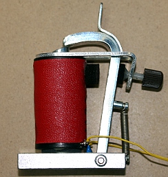 Pallet lifter magnet:
 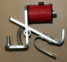 Pallet pusher magnet:
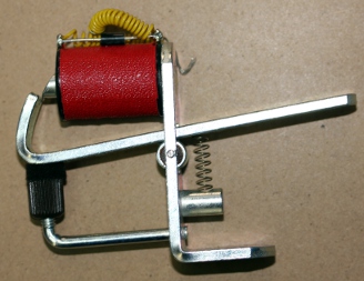
Stepping motor: MAE HY200 3424 T70
A8 b(Vmax = 90V, I = 1.7A/phase), we connected the phases in series to obtain
maximum torque at low speeds.
Stepping motor controller: IMS IB106
(Datasheet PDF) Current limiting
resistor: 120 Ohm. 
Dented wheels: Modul size 1. On motor:
KW410 020, on cradle: KW410 120. Gear ratio: 1:6. Source: Gallon n.v., Kruisboommolenstraat
11, 8800 Roeselare. URL: http://www.gallon.be
Tilt sensor: Penny & Giles (Price
270 Euro) Datasheet: (STT280.60.P2)
Data sheet. (PDF)
Compression driver: Padu, 16 Ohms
impedance, power 100W. This must be understood as 'peak power', and thus in
true rms terms would correspond to ca. 35 Watt sine wave. Thus the maximum voltage
that can be applied to the driver is 25V.
Wheels: 300mm spoke wheels with solid
polyurethane tires, ordered from Kaiser & Kraft
Power Supplies:
Note that there are no SMPS circuits in this robot. So, leakage currents are
minimal and MTBF should be maximal.
Metal work: Stainless steel AISI
306, all welding performed with the manual TIG technology using argon gas.
Midi-Hub board schematics:

firmware listing for this microcontroller
Hex-dump midihub board
Assembled PC board:
Finger solenoids microcontroller board:
firmware for this microcontroller
Hex-dump valve board
Assembled PC board:
Compressor driver board: http://www.st.com/stm32f4-discovery (all development
tools can be downloaded here)
Firmware for this board written by Johannes Taelman. Documentation
sheet on this board (PDF).
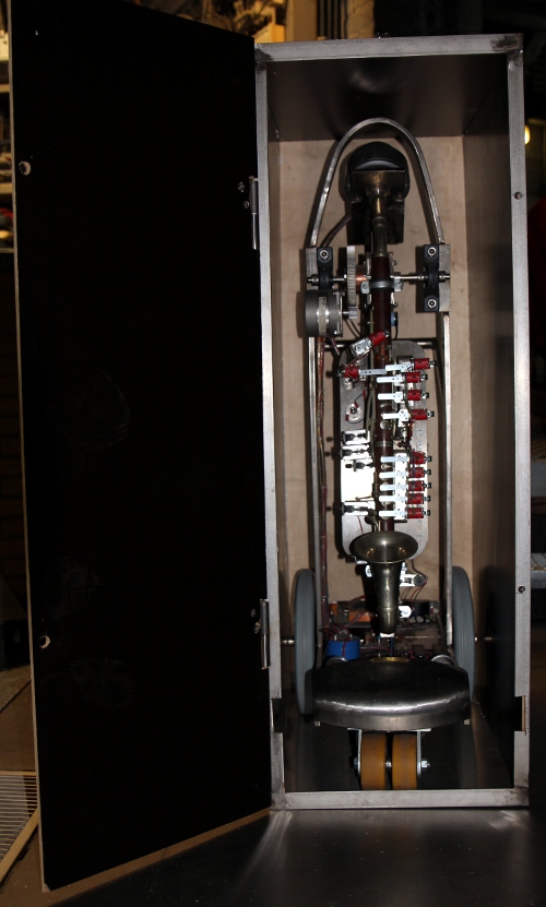
For transportation, the components designed for blocking the mechanism must
be mounted allways. They are shown in the picture:
<Klar> has a flightcase of its own. The sizes of this fightcase are 425
(width) x 690 (depth) x 1235 (heigth). The weight of the empty case is 30 kg.
Bibliography:
BAINES, Anthony "Woodwind instruments and their history", ed. Faber
and Faber Ltd., London, 1977 ISBN 0 571 08603 9
BARTOLOZZI, Bruno, 'New Sounds for Woodwind' , Oxford University Press, London
1982 (1967), ISBN 019 318611-x
BENADE, Arthur H., "Fundamentals of musical acoustics", Dover Publications
Inc., New York 1990 (1976). ISBN 0-486-26484-x
BRYMER, Jack "Klarinet" ed. A.J.G.Strengholt's boeken, Naarden, 1979.
ISBN 90 6010 501-X
CHEN, J.M., SMITH. J. and WOLFE, J. "Pitch bending and glissandi on the clarinet:
roles of the vocal tract and partial tone hole closure" (2009) J. Acoust. Soc.
America, 126, 1511-1520.
DICKENS, P., FRANCE, R., SMITH,. J. and WOLFE, J. "Clarinet acoustics: introducing
a compendium of impedance and sound spectra". (2007) Acoustics Australia, 35,
17-24.
ELSENAAR, E, "De Klarinet", ed. Harmonia Hilversum, 1927. (5e editie,
ongedateerd)
FRITZ, C. and WOLFE, J. "How do clarinet players adjust the resonances of their
vocal tracts for different playing effects?",(2005), J. Acoust. Soc. America
118, 3306-3315.
FRITZ, C., WOLFE, J. a.o. "Playing frequency shift due to the interaction between
the vocal tract of the musician and the clarinet". (2003) Proc. Stockholm Music
Acoustics Conference (SMAC 03), (R. Bresin, ed) Stockholm, Sweden. 263-266.
RAES, Godfried-Willem, "Expression control in automated musical instruments"
(2024)
RAES, Godfried-Willem, "<Klar>, a robot in per- and retrospective"
(2014) In: No Patent Pending, iii, 2014.
RAES, Godfried-Willem, "Logos @ 50, het kloppend hart van de avant-gardemuziek
in Vlaanderen" (boek, Uitgeverij Stichting Kunstboek, Oostkamp, 2018)
RENDALL, Geoffrey F. "The Clarinet, some notes on its history and construction",
ad. Ernest Benn Ltd., London 1971 (3th edition) (ISBN 0-510-36700-3)
RENES, Jules & VAN RICKSTAL, Jos "Handboek van den klarinettist",
ed. nv. de Nederlandse Boekhandel, Anrwerpen 1942
SMITH, Bob H., "An Investigation of the Air Chamber of Horn Type Loudspeakers",
in: The Journal of the Acoustical Society of America 25, 305-312 (1953); https://doi.org/10.1121/1.1907038
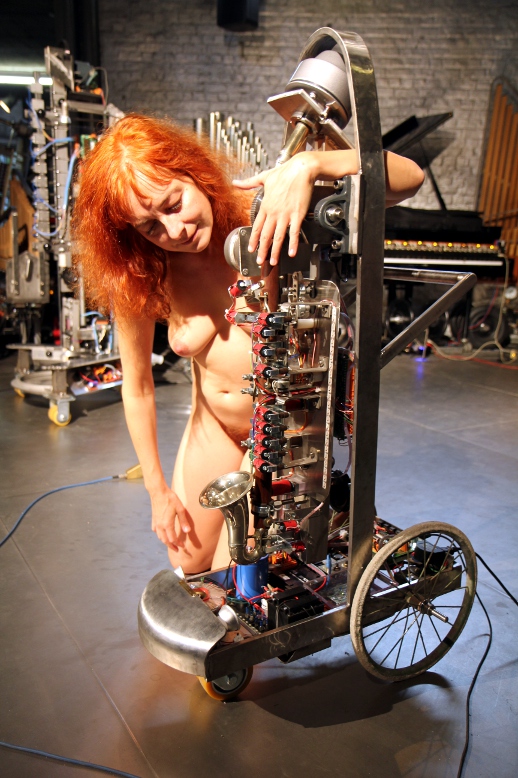
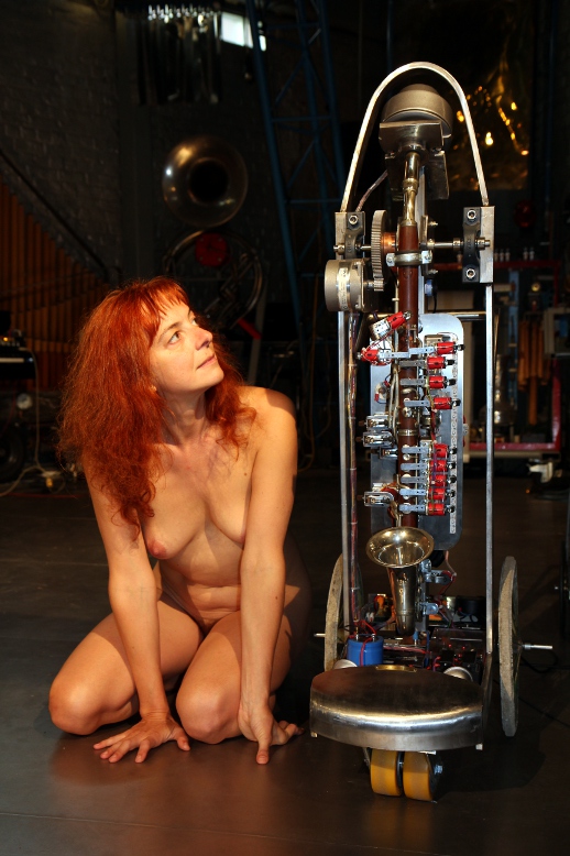
Robodies pictures with <Klar>: