|
<HarmO>
|
|
Research
project on the development of new tools for musical expression at
the University College Ghent

Godfried-Willem RAES
2009/2010
|
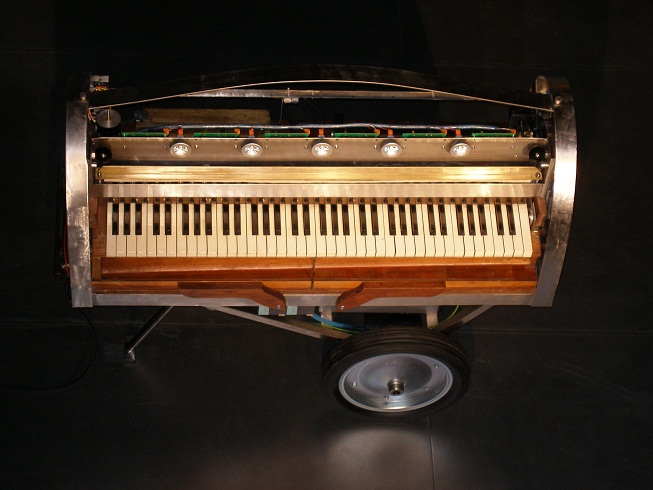
Technical Description
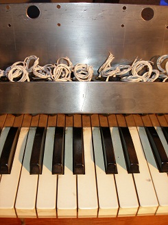
A computer controlled 6-octave reed organ with touch control, swells and individual
registration. The starting point for this construction was an old Emile Kerkhoff
(1887-1956) suction reed organ, of which we only kept the reeds and the key
springs. A new electric compressor was added (a small Laukhuff Ventola, rated
for 80mm H2O pressure (800 Pa) and 3000 l/min) replacing the bellows. The instrument
has 4 sets of reeds for the bass side and 4 sets of reeds on the treble side.
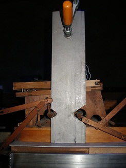
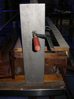
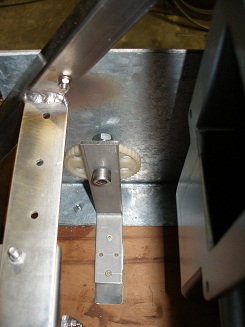
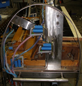
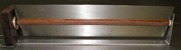
In addition it is equipped with 1 octave (13 reeds) of reeds for a subbass.
These sound the notes 12 -24. 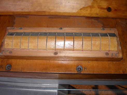 The
picture shows the note valves for this subbass with the box resonator removed.
Taking the registers into account, the real sounding ambitus ranges from midi
note 12 to 113, or an impressive eight and a half octaves!
The
picture shows the note valves for this subbass with the box resonator removed.
Taking the registers into account, the real sounding ambitus ranges from midi
note 12 to 113, or an impressive eight and a half octaves!
Two swells are provided, as well as a reflective tremulant mechanism. In total
the organ has 305 reeds. Although the instrument is signed and labeled Kerkhoff,
we have doubts with regard to the real builder. It may very well be an American
made Beckwith reed organ (Type: Grand Orchestral Action G, 6 octaves 18 stops).
Embossed in the back of the triplex soundboard, it carries the series number
54938.
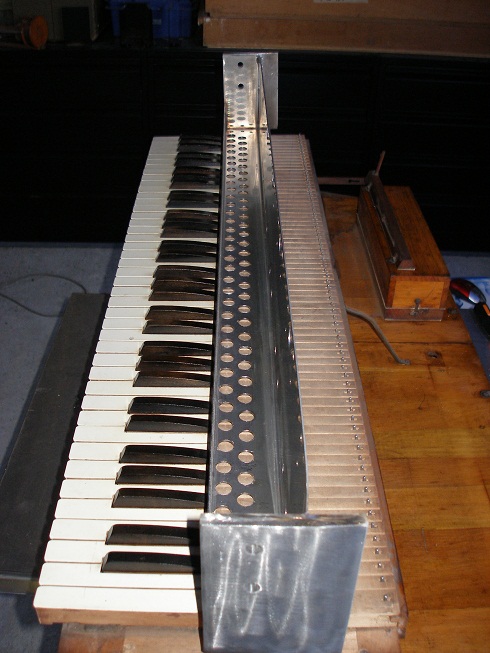
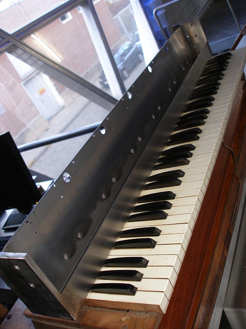
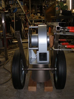
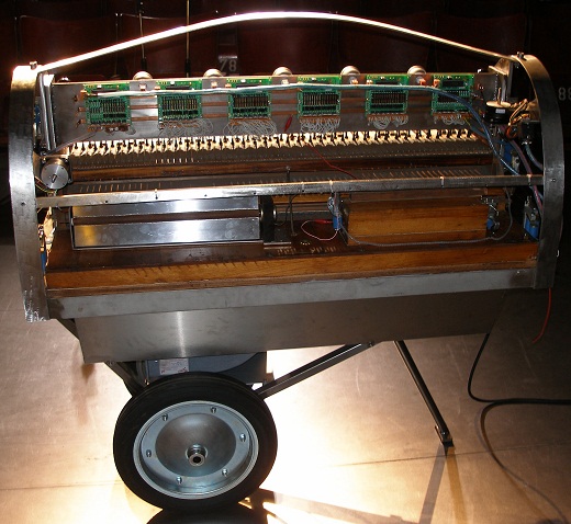
As usual in our automated instrument designs, we designed a sturdy welded
frame made in stainless steel for the entire magnet and electromechanical assembly.
As a reminder: we favor AISI304 stainless steel not only for its visual qualities
and freedom of maintenance, but also because it is a nonmagnetic material. Other
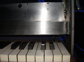
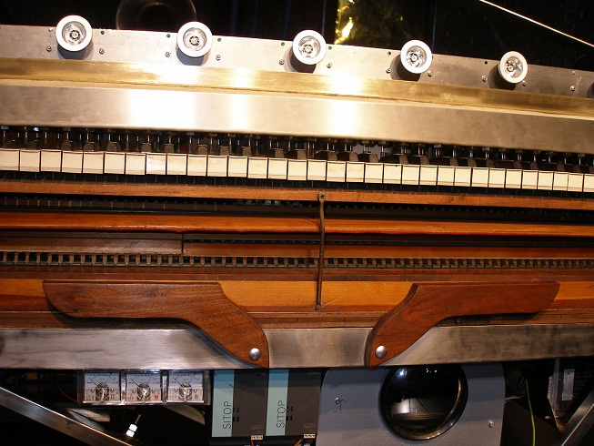
than in our first robot reed organ, here we decided to leave the original keyboard
in place. As a consequence, it becomes possible to play the organ in the traditional
way even in combination with automated playing. For registration and expression
control however, we did not foresee a manual alternative. We used tubular solenoids,
20 mm in diameter, to activate the keys here serving as levers to reduce the
required force to push the pallets down. This saved us the work of replacing
all pallet springs with lighter ones as we did in <Harma>. Since the magnets
are wider then the distance between keys/pallets (13.5 mm), we had to mount
them on alternating rows. This became another reason for not activating the
pallets directly. The eight registers are each divided in a bass and a discant
unit. So we provided also control for these 8 registers. Although we first wanted
to implement this using solenoids with variable voltage , such that gradual
changes ('expression') would become possible, some experimentation revealed
that the small benefit was not worth the effort and increase in complexity.
Gradual opening of the register shutters did just not produce the expected result.
However, gradual opening of the dynamic shutters appeared to be an interesting
feature worth implementing. Our first attempt using soft shift linear solenoids
to this end were not successful because these solenoids did not produce enough
pulling force to guarantee a smooth action. Therefore we finally decided to
use linear stepper motors with a threaded shaft. This approach makes a smooth
action possible at the expense however, of some extra noise caused by the audible
stepping frequency. Although this mechanism is relatively low in action, the
big advantage of it is that it draws no current to keep position, but only so
on movement. The whole traject from closed to fully opened takes about 500 ms.
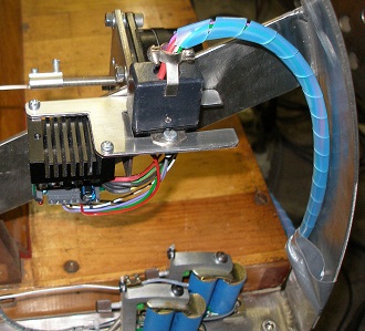
The design of the tremulant was quite adventurous in some respects. At first
it appeared that we had about four options:
- 1. Leaving the original pneumatic motor driven mechanism in place and switching
it on/off using a solenoid.
- 2. Using a 35 mm Laukhuff pallet valve mounted right on the whole in the
windchest.
- 3. Using a softshift solenoid driving a conical valve.
- 4. Using a solenoid driven bellow to modulate air pressure.
The first solution, although the easiest one, suffers from the fact that the
speed of rotation of the tremulant becomes a function of wind pressure and
thus cannot be controlled independently. Also the mechanism tends to be shaky,
fragile and causes some noise.
The second solution - very easy to implement- works pretty well but suffers
from a rather square wave like behavior. Also, when the valve is opened, the
air flowing in makes quite some noise.
The third solution requires the construction of a very well machined conical
valve with a traject of 10 mm. Its operation becomes as smooth as one wishes
since it becomes possible to steer it with a very low frequency sine wave
of variable amplitude. Of course other wave forms would lead to different
amplitude modulation envelopes.
The fourth solution leads to the best results. When a large loudspeaker -a
powerful woofer- is used as a bellow, the pressure in the windchest can be
modulated even at very fast rates. However, the compressed volume should be
in a reasonable proportion to that of the entire windchest, thus dictating
the use of a speaker with a diameter of some 30 cm. This would make the instrument
much larger than what we had in mind. The same size argument does apply to
the solution using a solenoid driven bellow.
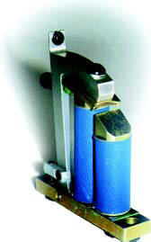
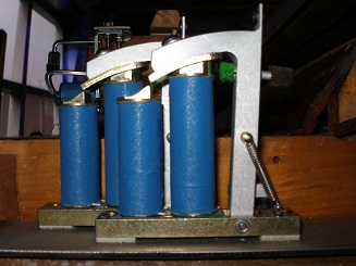
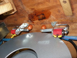
 Softshift
tremulant.
Softshift
tremulant. - As soon as we tried the second and third options (shown on the picture above),
we discovered that neither of them worked. Mounting the original pneumatic
mechanism, however worked fine... Clearly we made a fundamental mistake in
the way we understood the function of the tremulant. Rather than working on
modulation of the air pressure in the windchest -as usual in pipe organs-
, it worked merely on acoustic reflection of the sound on the large cardboard
blades of the rotator. In fact it makes use of the Doppler effect to create
a slight but real vibrato. Therefore we had to redesign the mechanism completely,
and since we wanted to have autonomous control over the modulation frequency,
we needed to build a reflector mechanism driven by a variable speed motor.
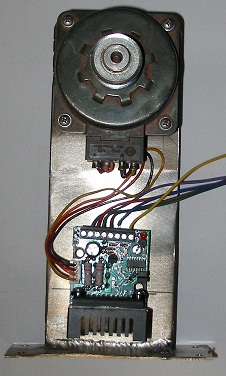
The use of a simple low power stepper, as used for the vibrato drivers on
our <Vibi> robot came into our mind, as these run really silently..
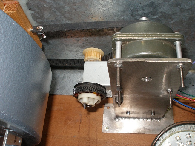
The radial compressor used for the wind supply is equipped with a wind regulating
slide mounted on the inlet of the windchest. This slide can also be controlled
and allows for faster wind pressure changes than can be achieved by regulation
the rotation speed of the motor. This slide is driven by a stepping motor coupled
to a dented belt. In the midi implementation this slide is mapped on the standard
windcontroller (nr. 1), whereas the motor speed is mapped on controller 7, the
general volume controller.
The note range of the instrument is 29 to 101 expressed in midi note commands.
Taking into account the registers (32', 16', 8', 4' and 2'), the real range becomes
17 to 113. Although in the design phase we considered making the instrument fully
polyphonic, we finally decided to limit polyphony on this automate to 32 notes.
For a full 73 note polyphony would have implied the construction of a hefty 45
A / 12 V power supply. Even though possible, the compressor would never have enough
wind to make all the reeds sound. Thus we decided to forsake full polyphony. Even
at 32 notes held simultaneously (particularly in the bass...) the wind supply
is barely powerful enough. The finished instrument has following dimensions: depth
490 mm, width 1165 mm, height 1000 mm. The weight is ca. 60 kg.
<HarmO> is controlled by no less than 13 PIC microcontrollers (6 for
the notes and the registers, 3 for the linear stepper motor controllers, 2 for
the compressor motor, 1 for the lights, the motor control signals and the tremulant)
and takes midi input directly. Of course the instrument can play standard midi
files. <HarmO> was designed from the beginning on with velocity control,
based on precise timing of an initial high voltage pulse to activate the note
solenoids. The effect of velocity control or touch sensitivity is of course
by far less effective than it is on our player piano or on the organs equipped
with conical windchest valves such as <Bomi>.
The speed wherewith the valves open in a reed organ being generally much faster
than the rather slow build up of a sound from the reeds. However, any touch
sensitivity a reed organ played by a human might have, is also implemented and
at least surpassed in this robot. In fact in this robot reed organ, we realized
a major improvement over the first similar but smaller reed organ robot,
<Harma>. The fact that this robot is tuned to 440 Hz, rather than
the 435 Hz on <Harma>, makes it more suitable for integration in our robot
orchestra.
In 2015 we added a new feature to the wind regulation mechanism: it now is
'intelligent' in that it will automatically adapt windflow to the notes effectively
played as well as to registers drawn and volume setting requested. It is no
longer possible for users to make the mistake to let the motor turn at full
speed (high volume setting) when no notes are being played. The firmware for
the wind motor control was revised a few times, the last revision is dated 27.11.2022.
There is still place for improvements though...
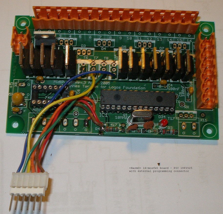
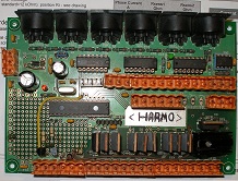
The circuit overview looks like this:
Circuit details as well as a very detailed building log can be found in the
service manual at the very end of this page.
Design and construction:
Collaborators:
- Kristof Lauwers, GMT coding
- Yvan Vander Sanden
- Moniek Darge
- Troy Rogers, construction assistence (Fullbright PhD student, Virginia University)
- Irs.Johannes Taelman, microcode PIC's.
Nederlands
<HarmO>
Tessituur: 29 (Fa) - 101 (Fa) [ 6oktaven ]
Hiervoor werd uitgegaan van een oud harmonium -volgens
het label althans- gebouwd door Emile Kerkhoff, een ambachtelijk wat aan lager
wal geraakte orgelbouwer gevestigd in Brussel. De gehele bouw lijkt als twee
druppels water op een Beckwith instrument, type 'Grand Orchestral Action
G, 6 octaves 18 stops'. Wellicht heeft Kerkhoff niet veel
meer zelf gebouwd dan de kast rond het instrument... Het instrument is voorzien
van acht onafhankelijke reeksen doorslaande tongen en werkt met zuiglucht, zoals
het gros van de naar Amerikaans model gemaakte 'reed organs'. Vier registers
voor de bas en vier voor de diskant. Als extra is het harmonium uitgerust met
een subbasregister bestaande uit 13 rieten geplaatst in een afzonderlijke bakje
dat als resonator dienst doet. Rekening houdend met de registers, strekt de
eigenlijke muzikale tessituur van dit instrument zich uit over acht en een half
oktaaf (12-113). De balgen en windlade verwijderden we integraal en werden vervangen
door een kompressor met motorbesturing, een Laukhuff Ventola zuigblazer. (3000
l/minuut, bij -80 mm H2O druk). Daar dienden we wel een goede geluidsdemper
voor te ontwerpen want geruisloos zijn deze Ventola blazers bepaald niet...
De kracht vereist om de paletten rechtstreeks, dus zonder
de hefboom gevormd door de toets en het eigen gewicht van de toets, in te drukken
maten we als 2.45 Newton (250 gF). Bij de bouw van <Harma>, ons eerste
robot harmonium, hadden we de kracht van de veren ongeveer gehalveerd teneinde
kleine Laukhuff elektromagneten te kunnen toepassen. Het nadeel van dat opzet
was dat het instrument makkelijk neiging heeft tot lekken wanneer druk in de
lade wordt opgebouwd zonder dat noten gespeeld worden. Dit euvel wilden we hier
vermijden. Buisvormige elektromagneten met een diameter niet groter dan 13mm
(wat vereist zou zijn om de magneten uitgelijnd met de paletduwers te plaatsen)
en een dergelijke kracht (2.45 N) worden niet gefabriceerd. Daarom maten we
de kracht nodig om de toetsen in te drukken en kwamen uit op 1.2 tot 1.5 Newton.
Heel wat minder dus, wat uiteraard te wijten is aan de werking als hefboom en
aan het eigengewicht van de toetsen.
Hartafstand tussen de bedieningspallen voor de rieten
was 13.54mm, waardoor we de magneten om en om (in twee rijen) dienden te monteren.
Wanneer we de bedieningsmagneten om en om monteren, mogen ze dan hooguit 27
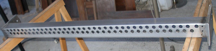
mm breed zijn. De gebruikte types zijn 20 mm breed. Voor deze montage plooiden
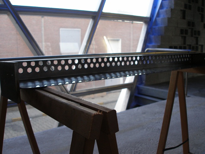
we een inox plaat van 2 mm dikte in een assymetrische U-vorm. In de onderzijde
daarvan werden de 73 gaten voor de montage van de elektromagneten geboord. Om
de automaat goed te kunnen afregelen, werd de gehele elektromagnetendrager zo
gemonteerd op de zijdelingse steunen, dat de hoogte ligging heel nauwkeurig
kan worden ingesteld.
De registers zijn telkens gedeeld in bas- en diskant.
Voor de automatisering daarvan gebruikten we elektromagneten met dubbele spoelen
van de firma Laukhuff. Er zijn 4 registers aan de baskant en 4 aan de sopraankant.
Daarbovenop komt nog het subbasregister. Voor de automatisering van de zwelkasten,
werden twee lineaire stappenmotoren van Nanotec toegepast. De toepassing van
soft-shift lineaire magneten hadden we oorspronkelijk voorzien, maar daarvan
dienden we uiteindelijk af te zien vanwege de te geringe kracht die deze komponenten
kunnen leveren (8 tot 13 Newton, terwijl we eigenlijk meer dan het dubbele nodig
bleken te hebben). Bovendien vormde ook het vermogen nodig om een bepaalde positie
aan te houden (21 Watt) een bezwaar. Lineare stappenmotoren met een schroefgang-as
houden hun positie wanneer ze volledig stroomloos worden gemaakt. De snelheid
van deze mechanismen is echter heel wat lager dan bij soft-shift magneten. Het
hele trajekt met de lineaire motoren neemt ca. 500 ms in beslag, terwijl dit
bij toepassing van soft-shift magneten slechts 45 ms zou duren.
De radiale kompressor is voorzien van een regelschuif,
gemonteerd aan de inlaat van de windlade. Deze regelschuif werd eveneens geautomatiseerd
en daarvoor ontwierpen we een mekanisme met een stappenmotor en een getande
riem. Hierdoor wordt een snellere regeling (ca. 200ms voor het gehele trajekt)
van de winddruk mogelijk dan wat voorzien is via sturing van het toerental van
de motor zelf. De windregelschuif werd gemapt op midi kontroller nr.1, terwijl
de motor snelheid gestuurd kan worden middels midi kontroller 7.
Voor de elektronische besturingen van de toonkleppen
gebruikten we onze eigen en beproefde ontwerpen voor muziekautomaten, meer in
het bijzonder, de schakelingen ontwikkeld voor onze player pianos en later in
talloze andere robots toegepast. Daardoor kon ook aanslaggevoeligheid worden
geimplementeerd. Hoogst ongebruikelijk voor een harmonium, maar we hadden het
al eerder gedaan bij de bouw van <Harma>, <Qt>, <Bomi> en
<Bako>. <HarmO> kan rechtstreeks via midi zowel als UDP/IP worden
aangestuurd. Ook de winddruk is heel nauwkeurig regelbaar, waardoor crescendos
perfekt mogelijk zijn. Dit effekt is trouwens op een andere wijze ook te bereiken
door gebruik te maken van de beide eerder genoemde zwellers.
Een klein grapje hebben we onszelf bij de bouw van deze automaat toch gepermiteerd:
een klopgeest werd ingebouwd... Ook die klopgeest kan via midi kommandos aan
de praat worden gebracht.
Niet minder dan dertien mikroprocessoren, elk voorzien
van eigen en onderling verschillende firmware, staan in voor de interne besturingen
van de diverse onderdelen van deze robot.
Tot de revizie die <HarmO> onderging in 2015 dienden
komponisten die voor deze robot wilden schrijven er terdege mee rekening houden
dat de winddruk geregeld moest worden in funktie van de gewenste dynamiek enerzijds,
maar ook in funktie van het luchtverbruik. We dienden er telkens wee op te wijzen
dat het luchtverbruik voor lage tonen heel wat groter is dan voor de hoge. De
vroeger meest voorkomende fout in midi bestanden, bestond erin de druk bij aanvang
van de track of partij in te stellen op een vaste waarde. Hierdoor echter werd
druk opgebouwd zonder rekening te houden met het al dat niet spelen van tonen.
Dit leidde niet alleen tot volkomen overbodig lawaai van de motor, maar ook
vaak tot lekken in de toonkancellen. De enige goede metode bestond erin, na
het inbrengen van de muzikale partij, de windkontroller instellingen (nr.7)
voor de gehele track te bepalen in funktie van de notentekst en de gewenste
dynamiek en expressie. In 2015 evenwel voegden we een microprocessor toe in
<HarmO> die de motorsturing volledig afhankelijk maakt van het effektieve
luchtverbruik en van het gewenste volume. Een aantal extra midi controllers
werden aan de implementatie toegevoegd. De meeste recente upgrade van de firmware
voor deze functie werd uitgevoerd op 27.11.2022. Er is wel nog ruimte voor verbeteringen
hier...
|
Tech-Specs -----------------------------------------------Technische
specifikaties:
Aanvang bouw: september 2009
Operationeel sinds december 2009, volledig
afgewerkt begin 2010.
Laatste software upgrade: 27.11.2022
Size------------------------------------------------------------------------------Afmetingen
van het afgewerkte instrument:
- diepte: 500 mm
- breedte 1165 mm
- hoogte 1080 mm
- Gewicht: 115 kg
Power--------------------------------------------------------------------------------------------------------Stroomvoorziening:
Insurance value (for organisors):
25.000 Euro
Rental / concerts:
This instrument can be rented from Logos Foundation. A technician from
logos will allways accompany the automate. The tariff is 750 Euro a
day. Transportation is possible with a normal not too small liftback
car.
|
|
Midi
Implementation
Midi Implementatie:
The midi channel for <HarmO> is set to
9 (if counting channels from 0, otherwise, 10)
- Note ON/ Note Off notes 29 to 101 with velocity byte. (real sounds:
17 - 113) The velocity byte steers the speed wherewith the keys are
depressed. This has no effect on sound volume but affects legato versus
staccato playing.
- The ghost beaters are mapped on midi notes 0
and 1 and have velocity implemented. Note off is not required here.
- 1: Wind controller: 176 + channel, 1,
value (This controls the wind slide) The full traject takes some 250ms
to complete. This controller can be used for moderately fast modulation
of the amplitude within the limits set by controller 7. The usefull
traject goes from 24 to 100.[temporarely disabled
- 2021]
- 7 : Volume controller: 176 + channel,7, value (This controls the frequency
for the compressor motor and thus the maximum windpressure). The default
value for wind pressure value is 64. (Motor frequency 44 Hz)
- 66: Motor ON/OFF: 176 + channel, 66, value (0 or any value between
1 and 127). The green LED on the motor controllerboard will lite up
when controller 66 is on.
- 67: One-shot controller used to reset the motor
controller if it stopped working due to a failure. [for expert use only].
To restart the motor after this acknowledge, controller 101 can be used.
- 68: Windpressure mode of operation. When set to 0 (the default] the
motor control will be 'intelligent', that is, motor speed will automatically
adapt to the register settings as well as to the notes played. When
set to 1, the motor will run only at a speed determined by controller
#7 (volume controller). As a warning, the blue led on the motor controller
board will light up when this controller is set to any other value than
zero.
- 69: not implemented in HarmO
- Registration makes use of controllers:
- 70: bass reg 1 (On/Off) ( 2' cor anglais, frontal swell ) (real notes
53 - 76)
- 71: bass reg 2 (On/Off) (8' diapason, frontal swell ) (real notes
29 - 52)
- 72: bass reg 3 (On/Off) (16' bourdon, back swell ) ( real notes 17
- 40)
- 73: bass reg 4 (On/Off) (4' principal , back swell) (real notes 41
- 64)
- 74: sub bass register (On/Off) (32' real notes 12 - 24)
- 75: treble reg 1 (On/Off) (4' cremona, frontal swell) (real notes
65 - 113)
- 76: treble reg 2 (On/Off) (8' forte, frontal swell) (real notes 53
- 101)
- 77: treble reg 3 (On/Off) (16' clarinet, back swell) (real notes 41
- 89)
- 78: treble reg 4 (On/Off) (8' oboe, back swell) (real notes 53 - 101)
- 79: frontal swell (0-127, value 0 closes the shutter completely, so
pp. )
- 80: back swell (0-127), value 0 closes the shutter completely, so
pp.)
- 82: Tremulant (0-127) analog output voltage for doppler tremulant
speed control. (0- 18Hz) Note that the tremulant is only effective for
notes higher than midi 67. Also for best effect the back swell has to
be opened and any one or more of the register controllers 77 and 78
have to be selected.
- 100: selection of lookuptable for the airflow
control This controller is for research purposes only. The default value
is 16. This value should only be set to different values by users that
are thoroughly familiar with the coding in the firmware of the motor
microcontroller. Unthougthfull use can crash the microcontroller. Check
the firmware in HarmO_motor.bas
before using this.
- 101: This controller, for expert use only, switches
the motor controller on or off, irrespective of the setting for controller
66. It can be used after an error occurs with the motor controlller
that is reset with controller 67, to switch the motor back on without
resetting other controllers.
- 123: AllNotesOff: 176 + channel, 123, 0. No controllers are affected
by this command.
- Program change command (192 + channel, patch)
Program changes with patch numbers between 122 and 127 let users select
different lookup tables for the velocity scaling of this instrument.
The lookup tables can be changed using sysex commands. Pincode: horm.
The optimum velocity scaling will be obtained by sending a program
change nr.122 command.
- Lights: mapped on notes 119-127
- 127 = yellow/amber light under Vorsetzer mechanism (LED strip).
Light intensity mapped on the velocity byte.
- 126-122 = orange/yellow LED spots
frontal on the Vorsetzer mechanism
- 121 = bright red light on tremulant mechanism
- 120 = white LED spot underside. Note that
this light, by design, always switches between dim and full on.
It cannot be fully off. [2021: now replaced with a red light!]
- 119 = frontal blue light, floor oriented
|
| note: features printed in white
are still to be implemented on the date of this writing. |
Repertoire (all
repertoire playable on <Harma> can also be played on <HarmO>:
| Johann Sebastian Bach: |
Goldberg Variationen (available on CD in a limited edition LPD-001 ('minus
1')
a specific version for <HarmO> is available as well.
|
|
| |
Das Wohltemperierte Klavier |
|
| Ludwig Van Beethoven |
Waldsteinsonate |
|
| Tango's |
La Cumparsita Tango |
|
| |
El choclo Tango |
|
| |
Jealousy Tango |
|
| |
Uno |
|
| Godfried-Willem Raes |
<Harm> for Harma |
2001 |
| |
<Hidden (c) Harms>
 MP3
encoded recording of this piece (on Harma) MP3
encoded recording of this piece (on Harma)
|
2001
2010
|
| |
<Vibes> for Vibi, Piperola and Harma |
2001 |
| |
<Trio Paradiso>, for Vibi, Harma and Klung |
2001 |
| |
<Paradiso>, for automat orchestra and backing vocals |
2001 |
| |
<Tekne>, for automat orchestra and devils dance |
2002 |
| |
<Eary Lis Trimbl>, for automat orchestra and musicians |
2002 |
| |
<Flexes>, for automat orchestra and musicians |
2003 |
| |
<Wandern>, for radar controlled automat orchestra and a nude dancer |
2003 |
| |
<Pic Harm>, for picradar controlled Harma and a nude dancer |
2005 |
| |
<Gestrobo Study #HarmO>, for invisible instrument HarmO and a nude
dancer |
2010 |
| Kristof Lauwers |
<Sonata>, for automat orchestra |
2002 |
| Sebastian Braadt |
<Dedication Harma> |
2004 |
| |
<Early Messages> |
2004 |
Service manual & detailed circuit
and maintenance documentation
Following information and documentation is not intended for the general public.
Radial compressor: August Laukhuff, Ventola type 612380. Motor 130 Watt, aussenlaufer.
Star connected for 3-phase operation with Siemens motorcontroller. Windpressure
800 Pa, 3000 l/min when operated on 50 Hz. Rotation speed at 50Hz: 2800 rmp.
Machine number: 6082-8129. Price: 1.309,12 Euro (11/2009)
Tubular solenoids (73): Black Knight 121-420-620-620 (100% duty cycle voltage
12V, diameter 20mm, push type). Resistance: 20ω
Register solenoids (8): Aug.Laukhuff Trakturmagnet, 300810, 24V (10 Newton,
10mm traject) Price: 39,86 Euro (11/2009)
Subbass register solenoids (2): Aug.Laukhuff Ventilmagnet, 24V
Linear stepper motors (2): Nanotec L5609X2008- M6x0.5 (Farnell order nr.: 474-3234).
Shaft: ZSM6-0.5-200 spindle, M6x0.5 (Farnell order nr.: 837-5682). Corresponding
motor controllers: Nanotec SMC42-2,0-1 (Farnell order nr.: 474-3131). Wiring
details:
Windvalve inlet motor: Burroughs Sonceboz type nr. 1251 0228, rated 0.6A/phase
and 0.5 Ohms/phase. Bipolar stepper motor. Dented belt: 78mm length, Gates powergrip.
Connected to the 24V power, the motor draws 1.2A when running with a 186Hz clock.
At 240Hz, it draws 840 mA. This seems to be the optimum clock frequency for
this motor.
Doppler tremulant motor: Canon, 6V type R17CN-EQCB, diameter 41mm, fully screened,
made in Taiwan.
Circuit boards overview:
Power supply:
2 Siemens Sitop Smart 24 V/10 A, nr.6EP1334-2AA01 (Output voltage adjustable
from 22.8 to 28 V) Farnell order nr.: 121-6632
1 Mascot 8921 12 V PSU, desktop 290 W, 20A ( http://www.mascot.no ) Farnell
order nr.: 118-3937
1 5 V/ 1 A, encapsulated module.VxI 14438/000 (http://www.vxipower.com). Farnell
order nr.: 118-6397
3 analog panel meters are provided for power supply monitoring. Therefore Kyuritsu
KM-48 voltmeters, rated 10 V DC, are used. For monitoring the 12 V, a 1% series
resistor of 5 k was used such that a reading of 8 V on the original scale now
corresponds to 12 V. For the two 24 V supplies, the 1% series resistor becomes
20 k. The meters Ri being 10 k and sensitivity 1 mA.
6 boards for the note pallets:
All note solenoids have a common positive voltage connection. The second wires
come together in Weidmueller 6-pole connectors (one for each set) to the note/velo
boards. To get access to the reeds and the springs, first disconnect all these
connectors. Next, remove the U-shaped stainless steel protectors. Then loosen
the bolts joining upper and lower part of the instrument. The solenoid assembly,
the vorsetzer, can be lifted up vertically from the soundboard containing the
reeds. Always keep components in a horizontal position! When the vorsetzer is
taken out, always take care to place it on two stand off blocks such that the
mechanism never comes to rest on the solenoid pushers.
The positive voltage can be adjusted on the power supply (Mascot) printed circuit
board with the multiturn trimmer. The voltage should be adjusted such that when
no velocity pulses are applied, the solenoids develop just enough force to hold
the keys down. Initially we found 8V to be a suitable minimum setting. The maximum
allowable voltage here is +12V. The negative voltage (the first Sitop power
supply) should be adjusted between 20V and 28Volts. Initially we had it set
to 24V. Changing this voltage will change the velocity scaling of the instrument.
The second Sitop power supply is adjusted to 24V positive and feeds the stepping
motors.
The circuitry on the midi input board and the PIC with the motor control worked
out like this:
Wiring tables for the six PIC 18F4620 controller boards:
Board 1:
| board output |
connector pin |
mapping |
remarks |
PIC pin |
| 1 |
2 |
reg, ctrl 70 - 2' |
gnd- -24V |
3 |
| 2 |
3 |
reg, crtl 71 - 8' |
gnd- -24V |
5 |
| 3 |
4 |
reg, ctrl 72 - 16' |
gnd- -24V |
7 |
| 4 |
5 |
reg, ctrl 73 - 4' |
gnd- -24V |
9 |
| 5 |
7 |
reg, ctrl 74, 32' subbass
|
gnd- -24V |
37 |
| 6 |
8 |
light, note 127, Yellow LED strip under pushers
|
keys bottom 12V |
36 |
| 7 |
9 |
note 29 |
pulse/hold |
34, 33 |
| 8 |
10 |
note 30 |
pulse/hold |
30, 29 |
| 9 |
12 |
note 31 |
pulse/hold |
28, 27 |
| 10 |
13 |
note 32 |
pulse/hold |
24, 23 |
| 11 |
14 |
note 33 |
pulse/hold |
22, 21 |
| 12 |
15 |
note 34 |
pulse/hold |
15, 16 |
| 13 |
17 |
note 35 |
pulse/hold |
17, 18 |
| 14 |
18 |
note 36 |
pulse/hold |
19, 20 |
Board 2:
| board output |
connector pin |
mapping |
remarks |
PIC pins |
| 1 |
2 |
note 37 |
hold/velo |
4, 3 |
| 2 |
3 |
note 38 |
|
2, 5 |
| 3 |
4 |
note 39 |
|
6, 7 |
| 4 |
5 |
note 40 |
|
8, 9 |
| 5 |
7 |
note 41 |
|
10, 37 |
| 6 |
8 |
note 42 |
|
36, 35 |
| 7 |
9 |
note 43 |
|
34, 33 |
| 8 |
10 |
note 44 |
|
30, 29 |
| 9 |
12 |
note 45 |
|
28, 27 |
| 10 |
13 |
note 46 |
|
24, 23 |
| 11 |
14 |
note 47 |
|
22, 21 |
| 12 |
15 |
note 48 |
|
15, 16 |
| 13 |
17 |
note 49 |
|
17, 18 |
| 14 |
18 |
note 50 |
|
19, 20 |
Board 3:
| board output |
connector pin |
mapping |
remarks |
| 1 |
2 |
note 51 |
|
| 2 |
3 |
note 52 |
|
| 3 |
4 |
note 53 |
|
| 4 |
5 |
note 54 |
|
| 5 |
7 |
note 55 |
|
| 6 |
8 |
note 56 |
|
| 7 |
9 |
note 57 |
|
| 8 |
10 |
note 58 |
|
| 9 |
12 |
note 59 |
|
| 10 |
13 |
note 60 |
|
| 11 |
14 |
note 61 |
|
| 12 |
15 |
note 62 |
|
| 13 |
17 |
note 63 |
|
| 14 |
18 |
note 64 |
|
Board 4:
| board output |
connector pin |
mapping |
remarks |
| 1 |
2 |
note 65 |
|
| 2 |
3 |
note 66 |
|
| 3 |
4 |
note 67 |
|
| 4 |
5 |
note 68 |
|
| 5 |
7 |
note 69 |
|
| 6 |
8 |
note 70 |
|
| 7 |
9 |
note 71 |
|
| 8 |
10 |
note 72 |
|
| 9 |
12 |
note 73 |
|
| 10 |
13 |
note 74 |
|
| 11 |
14 |
note 75 |
|
| 12 |
15 |
note 76 |
|
| 13 |
17 |
note 77 |
|
| 14 |
18 |
note 78 |
|
Board 5:
| board output |
connector pin |
mapping |
remarks |
| 1 |
2 |
note 79 |
|
| 2 |
3 |
note 80 |
|
| 3 |
4 |
note 81 |
|
| 4 |
5 |
note 82 |
|
| 5 |
7 |
note 83 |
|
| 6 |
8 |
note 84 |
|
| 7 |
9 |
note 85 |
|
| 8 |
10 |
note 86 |
|
| 9 |
12 |
note 87 |
|
| 10 |
13 |
note 88 |
|
| 11 |
14 |
note 89 |
|
| 12 |
15 |
note 90 |
|
| 13 |
17 |
note 91 |
|
| 14 |
18 |
note 92 |
|
Board 6:
| board output |
connector pin |
mapping |
remarks |
pic pin |
| 1 |
2 |
note 93 |
hold/pulse |
4, 3 |
| 2 |
3 |
note 94 |
|
2, 5 |
| 3 |
4 |
note 95 |
|
6, 7 |
| 4 |
5 |
note 96 |
|
8, 9 |
| 5 |
7 |
note 97 |
|
10, 37 |
| 6 |
8 |
note 98 |
|
36, 35 |
| 7 |
9 |
note 99 |
|
34, 33 |
| 8 |
10 |
note 100 |
|
30, 29 |
| 9 |
12 |
note 101 |
hold/ pulse |
28, 27 |
| 10 |
13 |
light
note 121
|
bright red (LED assembly, oriented to tremulant)
|
24 |
| 11 |
14 |
reg, 8' forte |
gnd- -24V |
21 |
| 12 |
15 |
reg, 16' |
gnd- -24V |
16 |
| 13 |
17 |
reg, 8' clarinet |
gnr- -24V |
18 |
| 14 |
18 |
reg. 4' oboe |
gnd- -24V |
20 |
Detail of the three different ways these boards are populated, depending on
the functionality:
Board 7 - Midi-hub board: (PIC 18F2525), board version 2006.This board originally
controlled the radial compressor motor, now it does the swell motors and the
tremulant DC-motor. The board is mount under the windchest on a piece of polycarbonate.
| board output |
connector pin |
mapping |
remarks |
wire color |
pic pin |
| |
X17-1 |
- |
GND |
|
- |
| 1 |
X17-2 |
ctrl 7 |
motor speed (0-10V) |
|
13 |
| 2 |
X17-3 |
ctrl 82 |
tremulant (0-10V) this mosfet has a small cooling
fin. |
DC motor Canon (6V) |
12 |
| |
X17-4 |
- |
+10 V from motor ctrl. |
|
- |
| |
X11-1 |
|
GND |
|
- |
| 3 |
X11-2 |
ctrl 66 |
wind motor ON/OFF |
|
5 |
| 4 |
X11-3 |
|
spare (optional sensor input front swell) |
|
4 |
| |
X11-4 |
|
+ 24 V from motor ctrl. |
|
- |
| |
X12-1 |
|
GND |
black/white |
- |
| 5 |
X12-2 |
|
frontal swell enable |
gray |
3 |
| 6 |
X12-3 |
|
frontal swell clock |
green |
2 |
| |
X12-4 |
- |
nc |
|
- |
| |
X15-1 |
- |
GND |
green/yellow |
- |
| 7 |
X15-2 |
|
frontal swell direction |
purple |
25 |
| |
X15-3 |
|
back swell enable |
brown |
24 |
| 8 |
X15-4 |
|
nc |
|
- |
| |
X16-1 |
GND |
|
|
- |
| 2 |
X16-2 |
=X17-3 |
tremulant (0-10V pwm) |
yellow
|
12 |
| |
X16-3 |
+ power |
tremulant positive supply +12V |
pink |
- |
| 9 |
X16-4 |
|
back swell clock |
orange |
16 |
| 10 |
X16-5 |
|
back swell direction |
yellow |
15 |
| |
X16-6 |
input |
sensor input back swell |
white |
7 |
Board 8 - Pulse board (PIC 18F2525) [board version rev.3, april 2005, modif..21.12.2009]
This board controls the ghost beaters, the windslide (ctrl.1), the ghost beaters
and the lites. This board is located on the same polycarbonate plate as the
midi-hub board and is located in the back of the mains power entry. The board
did in its original design not have a programming connector, but in this version
we constructed a 'flying' 6-pin connector such that in circuit debugging and
programming becomes possible as for all other processor boards in <harmO>.
| board output |
connector pin |
mapping |
remarks |
wire color |
pic pin |
| 1 |
X1-1 |
note 0 |
pulse beater 24V |
grey |
4 |
| 2 |
X1-2 |
note 1 |
pulse beater 24V |
purple |
3 |
| 3 |
X1-3 |
enable windslide motor
(green)
|
no BYV32 diode !
mosfet
|
green |
2 |
| 4 |
X1-4 |
windslide motor clock
(brown)
|
no BYV32 diode !
mosfet
|
brown |
5 |
| 5 |
X2-1 |
windslide motor dir
(blue)
|
no BYV32 diode !
mosfet
|
blue |
6 |
| 6 |
X2-2 |
analog input (R-sensor)
AN4 in PIC specs
|
no BYV32 diode
no mosfet!
|
nc |
7 |
| 7 |
X2-3 |
ICP - external connector |
avoid use |
yellow |
28 |
| 8 |
X2-4 |
ICP - external connector |
avoid use |
green |
27 |
| 9 |
X3-1 |
ICP - external connector |
avoid use |
blue |
26 |
| 10 |
X3-2 |
lite yellow. note 126 |
12V led spot |
brown |
25 |
| 11 |
X3-3 |
lite yellow. 125 |
12V led spot |
orange |
24 |
| 12 |
X3-4 |
lite yellow , 124 |
12V led spot |
yellow |
23 |
| 13 |
X4-1 |
lite yellow, 123 |
12V led spot |
green |
22 |
| 14 |
X4-2 |
lite yellow, 122 |
12V led spot |
blue |
21 |
| 15 |
X4-3 |
lite blue , 119 front lite above mirror |
12V led large spot |
blue |
16 |
| 16 |
X4-4 |
ac solid state relay
lite 120, white
|
white LED spot (230V) |
yellow |
15 |
| pwm |
X11 |
controller 81 |
analog pwm out
|
|
13 |
The 'flying' connector for in circuit debugging and programming is shown in
the picture below:
Power supplies:
- +12V dc (positive hold voltage): 20A, 260 Watt - SMPS power supply (Mascot)
- - 24V dc (negative pulse voltage): 10A Sitop (Siemens)
- +24V dc (register solenoids, stepper motors): 10A Sitop (Siemens)
- +5V dc logic power, 2A (Encapsulated module)
Programming information and settings for the Siemens Sinamics G110 motor
controller:
| Parameter nr. |
setting |
comment |
| P0003 - User Access level |
3 |
- 1= standard
- 2 = extended
- 3 = expert
|
| P0004 - access control filter params |
0 |
allow access to all parameters of P0003 = 3 |
| P0005 - display parameter |
21 |
display motor frequency |
| P0010 - commisioning params |
0 |
must be set to 1 to change motor params.
For access to P4 params and normal operation, must be set to 0
|
| P0100 - Europe/ US |
0 |
= default value (Europe, 50 Hz) |
| P0210 - voltage |
230V |
mains voltage |
| P0304 - nominal motor voltage |
230V |
motor specs. (star connected) |
| P0305 - motor current |
0.56A |
motor specs. |
| P0307 - motor power |
0.130 kW |
motor specs.motor specs. (name plate says 75 W, but current
is 0.55 A at 230 V) |
| P0310 - nominal motor frequency |
80Hz |
50 Hz after motor specs., but otherwise we cannot speed up... |
| P0311 - nominal motor rpm |
2800 |
motor specs. |
| P0700 - ctrl. via control panel or digital I/O |
2 |
use digital inputs for ctrl. |
| P1000 - select frequency setpoint |
2 |
set analog setpoint (1= operator panel f-ctrl) |
| P1080 - min.. motor frequency |
10 Hz |
|
| P1082 - max. motor frequency |
80Hz |
the practical maximum freq. will be ca. 60Hz |
| P1120 - ramp up-time |
2" |
|
| P1121 - ramp down time |
4" |
|
| P3900 - end quick commisioning |
1 |
resets P0010 |
With these settings we obtain the following midi correspondence:
| midi value for ctrl.7 |
motor frequency |
musical result |
| 1 |
10 Hz |
pppp |
| 5 |
|
|
| 10 |
|
|
| 20 |
|
|
| 30 |
28 Hz |
p |
| 40 |
35.5Hz |
mp |
| 50 |
40 Hz |
mf |
| 60 |
44 Hz |
mf |
| 70 |
|
|
| 80 |
50 Hz |
f |
| 90 |
|
|
| 100 |
56 Hz |
ff |
| 127 |
60 Hz |
fff |
Note that when no notes are being played, wind pressure should always be reduced
to the smallest practical value. Also, required wind pressure is a function
of the number of notes playing as well as of their pitch, since lower reeds
require a lot more wind than the high ones. With wind pressures higher than
midi value 60, leaks can occur when no notes are played. Since 2015 all these
problems have been adressed with a new intelligent motor controller. The remarks
are still valid, but are now solved in the firmware.
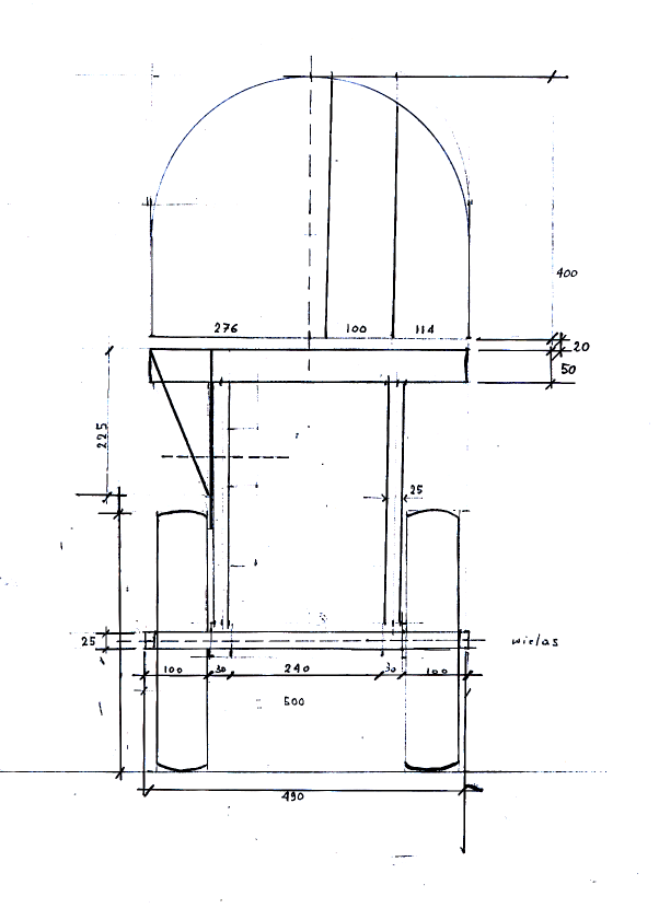
Metal parts sizing and drawings:
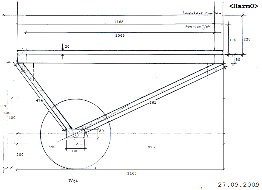
View from the bass side:
Lights:
- Five frontal yellow lights: 1W high power LED reflectors. Lifetime: 50000h.
GU5.3 socket, view angle 25 degrees, diameter 50mm. Voltage 12V. Forward current
350 mA. Operating temperature:-40C to +80C. Type: HomeStar 574568. Source:
Conrad.
- White LED spotlight on the bottom: QRB111. Voltage 230V ac. Switched with
a solid state relay. Lamp base: GU10. As a replacement, Verbatim #52045, 1206-162
can also be used.
- Yellow LED strips (flexible self adhesive strips with SMD LED's) rated for
12V dc.
- Bright red LED light oriented towards tremulant: LRW5SN VPA1A, 120 degrees,
Vf=3.3V. Two such LED's in series with current limiting wirewound power resistor.
(mapped on midi note 121)
Technical revisions and maintenance notes:
- 18.09.2009: Instrument signaled to us by Zimcke Van de Staey.
- 19.09.2009: purchase of the original Emile Kerkhoff instrument in Herselt.
Brought to Ghent by Yvan Vander Sanden. Basic tuning checked to be 440 Hz.
The case had to be taken apart in order to make the transport possible.
- 22-24.09.2009: Measurement of components, further dismantling of the original
instrument, first sketches for a new design.
- 26.09.2009: original instrument further taken apart and analyzed.
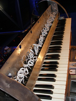
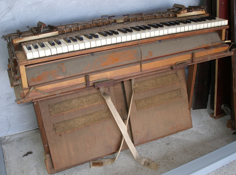 On the picture the instrument is shown in the state we received it in the
workshop.
On the picture the instrument is shown in the state we received it in the
workshop.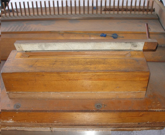 The sound board has a series number: 54938. After removal of the keyboard
assembly the box containing the 13 reeds for the subbass extension becomes
visible. The problem will be to make all the mechanics such that noise is
minimized. We decided to preserve the keyboard, since it seems to help reducing
the required solenoid forces for they function as levers. Solenoids ordered
from Farnell: Black Knight type 121-420-620-620.
The sound board has a series number: 54938. After removal of the keyboard
assembly the box containing the 13 reeds for the subbass extension becomes
visible. The problem will be to make all the mechanics such that noise is
minimized. We decided to preserve the keyboard, since it seems to help reducing
the required solenoid forces for they function as levers. Solenoids ordered
from Farnell: Black Knight type 121-420-620-620.
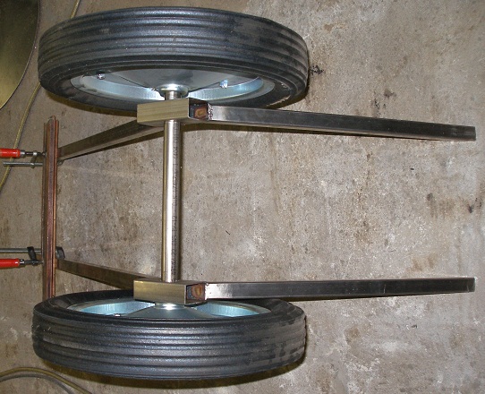
- 27.09.2009: TIG welding of the support frame for the bottom plate of the
windchest: 2 pieces 50x50x2 square tube, length 484mm welded on 50x3x1165mm,
flat stainless steel. Wheel axis tubing: 25 x 2 x 500. Wheels: 400mm diameter.
Ventola blower ordered from August Laukhuff. (order number 612380). This blower
will be mounted vertically, under the windchest. The bottom plate of the windchest
is to be mounted on this frame in a permanent way.
- 28.09.2009: Harmo building project shown and explained to Kristof Lauwers
and Troy Rogers. Further design of the wheelbase.
- 29.09.2009: TIG welding work on the frontal square tubing connecting the
wheel assembly to the windchest carrier.
- 30.09.2009: Further TIG welding work on the trolley. Some tuition given
to Troy Rogers on welding technology, metal working and robot construction.
- 01.10.2009: drawing of circuit overview. Estimation of board real estate
required.
- 02.10.2009: design session for the mechanics of the registers and expression
mechanism.
- 03.10.2009: Further work on the trolley construction.
- 04.10.2009: design of wind-inlet and motor mounting. Varnish restored with
polyvinyl alcohol.
- 05.10.2009: Drawing of the welding plan.
- 06.10.2009: Start construction of the solenoid holding structure. The structure
is a piece of stainless steel plate, 2mm thick bend in an asymmetric U shape:
140mm x 60mm x 50mm, cut to a length of 1050mm. Drawing, marking, centering
and drilling of the 73 holes, diameter 14.5mm, with the help of Troy Rogers.
Delivery of a first set of 29 solenoids from Farnell.
- 09.10.2009: Drilling and centering works.
- 11-12.10.2009: More drilling work... all 14.5mm holes drilled.
- 13.10.2009: 10mm thick side-plates for the 'vorsetzer' cut out. Placement
of the six note-control PC-boards decided: the will lean against the back
of the solenoid assembly. The wires from the solenoids will get through the
PC boards via large holes drilled in the backplate. This gives us space for
some lights on the frontal side.
- 14.10.2009: Further work on the vorsetzer design.
- 15.10.2009: T-shaped back bounce bar designed. This can be either made of
hardened brass or stainless steel 30x30. The flat side should have 6 to 10mm
thick felt. Measurement of required force to pull the registers: 5 Newton
(peak <=10 Newton) Thus August Laukhuff - Trakturmagnet, 24 V 0.5 A @ 100%DC
- 10 Newton
 can be used for all 8 registers. The power supply at 24V therefore will have
to be dimensioned for at least 4A at 24V continuous. A 100 Watt SMPS type
can be used. The front and back swell require a force smaller than 3 Newton,
when the needle return springs are removed. With the springs, the required
force is 10 to 15 Newton. We will try softshift solenoids: Ledex Softshift
type 5EP, number 193015-026. Cold DC resistance 10.3 Ohm. Nominal working
voltage at 100% duty cycle: 14 V (force = 8 Newton), at 50% (force = 18 Newton)
, 20 V, at 25% (force= 30Newton) , 28 V at 10%, 44 V (force= 50 Newton) .
Price (no joke): 144 US $ a piece... Since we expect most users to have the
swells opened most of the time, we should design for operation at 100% duty
cycle.
can be used for all 8 registers. The power supply at 24V therefore will have
to be dimensioned for at least 4A at 24V continuous. A 100 Watt SMPS type
can be used. The front and back swell require a force smaller than 3 Newton,
when the needle return springs are removed. With the springs, the required
force is 10 to 15 Newton. We will try softshift solenoids: Ledex Softshift
type 5EP, number 193015-026. Cold DC resistance 10.3 Ohm. Nominal working
voltage at 100% duty cycle: 14 V (force = 8 Newton), at 50% (force = 18 Newton)
, 20 V, at 25% (force= 30Newton) , 28 V at 10%, 44 V (force= 50 Newton) .
Price (no joke): 144 US $ a piece... Since we expect most users to have the
swells opened most of the time, we should design for operation at 100% duty
cycle.
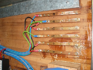
- 17.10.2009: Construction of the power supply bars in red copper. Drilling
of the 12 mm holes in the mounting flanges. Vorsetzer assembly welded together.
- 18.10.2009: Test assembly.
 Exact measurement of required solenoid travel on the different components
to be automated. The hold voltage for the key-solenoids will definitely not
have to be greater than 12V. If we would want to allow full clusters, this
would entail a power supply capable of delivering some 45 A. (500 Watt).The
velocity pulse voltage can be a relaxed 24 V and certainly not more than 48
V.
Exact measurement of required solenoid travel on the different components
to be automated. The hold voltage for the key-solenoids will definitely not
have to be greater than 12V. If we would want to allow full clusters, this
would entail a power supply capable of delivering some 45 A. (500 Watt).The
velocity pulse voltage can be a relaxed 24 V and certainly not more than 48
V.
- 19.10.2009: In place check & verify design:
 Sideplates to
carry the vorzetzer.
Sideplates to
carry the vorzetzer.
 Left en right side
pushing solenoids with rubber feet.
Left en right side
pushing solenoids with rubber feet.
- 20.10.2009: Wiring tables fixed for the pulse/hold boards. Bending of the
limiting side arc profiles (50 x 3 stainless steel) with Troy Rogers.
- 22.10.2009: News from Laukhuff: the compressor, as ordered, will be delivered
week 44, that is first week of November.
- 23.10.2009: Cutting and drilling of the four vertically mounted register
solenoid holding plates.
- 24.10.2009: further work on the carrying structure for the vorsetzer and
the register solenoids. The two solenoids on each side placed in a horizontal
plane are mounted with M3 bolts. The holes in the chassis are threaded. The
vertical ones are mounted with bolt and nut, M3. Mounting slots drilled and
filed out.
 \
\
- 25.10.2009: Mounting slots bass side filed out. Solenoids ordered from Laukhuff:
Trakturmagnet 24V, catalog number 300810. TIG welding work on the bass side
vorsetzer holder.
- 26.10.2009: Welding work on the arc, treble side after cutting out the arc
section in the thick vertical holding plate. Construction of a guiding wheel
with a 16mm outer diameter ball bearing for the movement of the frontal shutters.
- 27.10.2009: Bass side finished similarly as the treble side: arc cut out
and welded on the thick vertical plate. Removal of all needle springs on the
registers and the shutters. Experiments with the soft shift solenoids (Size
5EP, Lucas Ledex, order number 193015-026) carried out. At 100% duty cycle
operated on 14V dc these have a starting force of 8.8 Newton, at the end of
the 10mm stroke traject the force goes up a bit, reaching 13.3 Newton. Power
consumption under these conditions is about 21 Watt. Speed (unloaded) is ca.
45ms for the full traject. Wheel mounted on the key-holder plate. Pulling
thread connected to the frontal shutter.
- 28.10.2009: Linear stepper motors ordered as an alternative for the soft
shift solenoids: Nanotec L5609X2008-M6x0.5. This type has a thrust of 85 Newton,
a resolution of 0.00125 mm and a feed of 20 mm/s. Current per winding is 2
A. ( http://www.nanotec.com ). The cost (including the spindle, with a M6
x 0.5 thread, which is to be ordered separately) is about 120 Euro a piece.
We ordered stepper controllers for these motors (Type SMC42) and these cost
93 Euro a piece, bringing the price for the entire mechanism to about 426
Euro. Mounting plates with holes for either softshifts or these linear motors
made and welded into the treble side chassis.
- 29.10.2009: Design of the mechanism for the back shutters to be mounted
on the bass side chassis. Here the traject can be kept pure vertical without
any need for a guiding wheel. The way it looks now, we can probably go without
using sensors, on the sole condition that on startup, the shutter valves will
always be in a fully closed position. They can be brought there by hand, by
rotating the cylindrical part of the hollow bronze motor shaft. The midi controller
range 0-127 should be remapped on the number of rotations required for the
full traject. A counter should be kept in the software. Welding and mounting
works on the bass side chassis for the linear stepping motor.

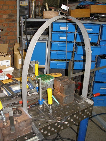
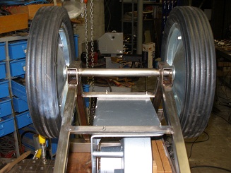
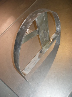 The pictures
show the welded and roughly brushed assembly for the bass side chassis with
no parts mounted.
The pictures
show the welded and roughly brushed assembly for the bass side chassis with
no parts mounted.
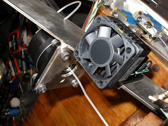
- 30.10.2009: Nanotec stepper motor controller delivered.
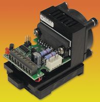 The fan will have to be removed since it is noisy and in this application
not even required, taking into account the duty cycle applicable to the shutter
valves. The controllers will be mounted right on the curved side chassis in
order to reduce possible EMC from the otherwise long wire bundles to the motors.
The motors have 8 wires and the windings are connected in series for full
bipolar operation. Mounting holes drilled in the side chassis. The controllers
are mounted with two M3 x 10 bolts.
The fan will have to be removed since it is noisy and in this application
not even required, taking into account the duty cycle applicable to the shutter
valves. The controllers will be mounted right on the curved side chassis in
order to reduce possible EMC from the otherwise long wire bundles to the motors.
The motors have 8 wires and the windings are connected in series for full
bipolar operation. Mounting holes drilled in the side chassis. The controllers
are mounted with two M3 x 10 bolts.
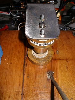
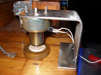
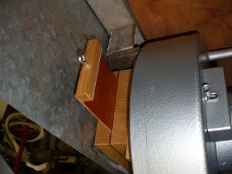
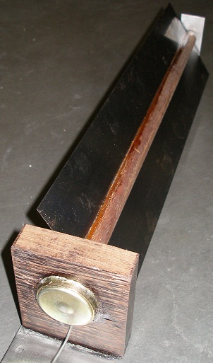
- 31.10.2009: Construction of the register lifter for the subbass box.
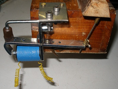 The picture shows the construction, but the felt washers are missing. The
solenoid is a small Laukhuff pallet lifter rated for 24V. The force at the
nominal voltage is too small to securely lift up the register valve, but when
driven with 30V it opens smoothly. The hold voltage can be kept at 24V. Another
solution would be to add a second solenoid -operating in parallel- at the
other side of the valve, thus doubling the force. That's the way we decided
to go, for it saved us complications with too many different power supply
voltages. Experiments did reveal that it would be possible to use the registers
in a gradual way, provided they are always switched off with the full voltage
and then lowering this voltage with PWM. The down traject is very well controllable,
not the upwards traject.
The picture shows the construction, but the felt washers are missing. The
solenoid is a small Laukhuff pallet lifter rated for 24V. The force at the
nominal voltage is too small to securely lift up the register valve, but when
driven with 30V it opens smoothly. The hold voltage can be kept at 24V. Another
solution would be to add a second solenoid -operating in parallel- at the
other side of the valve, thus doubling the force. That's the way we decided
to go, for it saved us complications with too many different power supply
voltages. Experiments did reveal that it would be possible to use the registers
in a gradual way, provided they are always switched off with the full voltage
and then lowering this voltage with PWM. The down traject is very well controllable,
not the upwards traject.
- 01.11.2009: Construction
of the tremulant mechanism using a softshift solenoid and a conical valve.
The seating for the valve was milled out in hard wood, such that it can be
glued right on the 16mm hole for the original tremulant, in the soundboard.
Start mounting of the key pressing solenoids on the Vorsetzer chassis. The
nuts are fixed with Loctite 243 (blue).
- 02.11.2009: Assembly of the spindle motors and controllers:
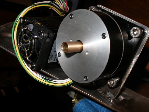
 The fans have
to be removed. The first picture shows the horizontal spindle motor driving
the frontal swell, the second the vertical spindle motor driving the backside
swell. Start soldering work on the note driver boards. The bass side board
is only fully populated for the highest 8 outputs. Series diodes here are
BYV28 - 200V. Mosfets: all IRL640, P-channel mosfets: BSP254A. It is harmless
to mount all P-channel mosfets, regardless the way the board is used. Troy
Rogers is helping us out with the soldering works on these boards. Boards
2-5 are identical, boards 1 and 6 have a slightly different component selection
due to the use of outputs for the register solenoids. Just for the sake of
comparative measurement and evaluation, we populated the high note board (board
6) with BS250 P-channel mosfets and did all soldering lead-free.
The fans have
to be removed. The first picture shows the horizontal spindle motor driving
the frontal swell, the second the vertical spindle motor driving the backside
swell. Start soldering work on the note driver boards. The bass side board
is only fully populated for the highest 8 outputs. Series diodes here are
BYV28 - 200V. Mosfets: all IRL640, P-channel mosfets: BSP254A. It is harmless
to mount all P-channel mosfets, regardless the way the board is used. Troy
Rogers is helping us out with the soldering works on these boards. Boards
2-5 are identical, boards 1 and 6 have a slightly different component selection
due to the use of outputs for the register solenoids. Just for the sake of
comparative measurement and evaluation, we populated the high note board (board
6) with BS250 P-channel mosfets and did all soldering lead-free.
- 03.11.2009: Continuation of soldering works. We run out of diodes... fast
order to Farnell. Three board are already fully populated and finished. Three
more to go... The picture shows board 6, with special component selection
in order that the same board can be used for switching 4 registers, one light
and nine notes.
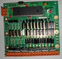 Since
the register solenoids are switched to the negative 24V supply, the protection
diodes (BYV32) have their central pin connected to ground. In order to gain
some more experience in future technologies (Sn/Pb solder may disappear...)
, we soldered this board leadless. It looks dull...
Since
the register solenoids are switched to the negative 24V supply, the protection
diodes (BYV32) have their central pin connected to ground. In order to gain
some more experience in future technologies (Sn/Pb solder may disappear...)
, we soldered this board leadless. It looks dull...
- 04.11.2009: Work on the red copper power supply bars connecting the boards
on the backside of the vorsetzer. The missing tracker solenoids from Laukhuff
have flown in and thus the register automation can be finished as well. Orders
placed for two Siemens Sitop 24V/10A supplies as well as for a 20A 12V supply,
made in Norway. Lets pray they come without fans and can cope with the surges
caused by the switching solenoids... With these components in the power supply,
polyphony will be limited to 32 notes simultaneous. We decided not to provide
full 73 note polyphony (requiring a 45A power supply for the +12V) because
the compressor would never be capable to provide enough wind to make all those
reeds sound properly.
- 05.11.2009: delivery of the compressor as ordered, only... Laukhuff did
mount the regulation valve on the suction side, whereas we wanted it on the
wind inlet side... This way it does not fit on the trolley we have already
welded together. Finalisation of the board soldering works after delivery
of the missing diodes by Farnell. The power supplies came flowing in and they
are fan-less!
- 06.11.2009: Preliminary mounting and assembly of the entire robot with clamps.
Verification of the construction drawings. Start construction of the windchest
inlet for the compressor.
 Opening of
the original windchest and pallet/reed check. We took the decision to leave
the slider wind control on the suction side.
Opening of
the original windchest and pallet/reed check. We took the decision to leave
the slider wind control on the suction side.
- 07.11.2009: Welding works on the trolley. Design of an automation for the
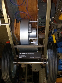
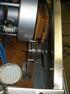
windvalve; a motor driven dented belt seems appropriate here.
 The windchest slider can be seen on the picture. The motor, the rotor is clearly
visible, mounted on its supporting bars:
The windchest slider can be seen on the picture. The motor, the rotor is clearly
visible, mounted on its supporting bars: 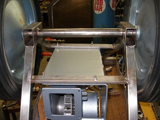
 We may even have enough space for the power supply (12V/20A) under the bottomplate
of the motor. Closing blocks made from teakwood for the closing sides of the
windchest inlet. These are glued on with silicone compound. After curing,
we will close the windchest with a plate of 2mm thick stainless steel, 960mm
x 24mm.
We may even have enough space for the power supply (12V/20A) under the bottomplate
of the motor. Closing blocks made from teakwood for the closing sides of the
windchest inlet. These are glued on with silicone compound. After curing,
we will close the windchest with a plate of 2mm thick stainless steel, 960mm
x 24mm.
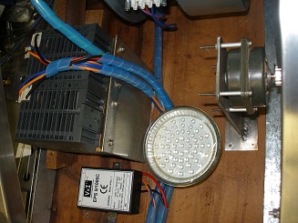
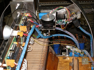
- 08.11.2009: Positioning of the power supply components and the Siemens motor
controller. Mounting brackets made for motor controller, two Siemens power
supplies (rail mount) and the 12V power supply. Power wiring can start now.
The 5V power supply still has to be given a place. Windchest closed with 2mm
stainless steel plate. Recycled antique power switch mounted under the windchest.
In this picture we see the 12V power supply mounted under the motor:
 This picture shows the two Siemens 24V power supplies:
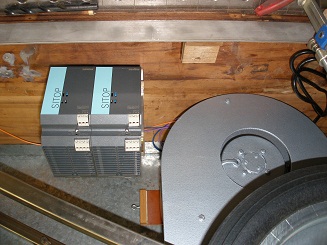 This is a view from underneath, showing the now completely closed windchest
inlet:
This is a view from underneath, showing the now completely closed windchest
inlet:  This
picture shows the positioning of the motor controller such that it is easy
accessible for the programming of the motor parameters:
This
picture shows the positioning of the motor controller such that it is easy
accessible for the programming of the motor parameters: 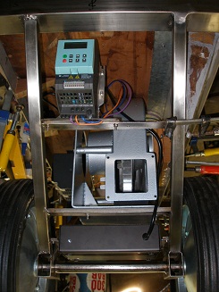
- 09.11.2009: Placement of 5V power supply. Design of the mounting of the
power inlet, the midi hub board and the extra required board for the ghost
and the steppers. Wiring of the all mains connections as well as the power
switch. The motor is now star-connected for operation on 3-phase 230V.
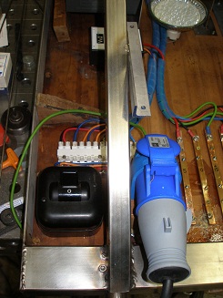
- 10.11.2009: Mounting of the mains power inlet (male CEE blue). Cutting out
of a polycarbonate carrier plate for the midi input board. Check of motor
operation. Should we provide build in metering/monitoring of the critical
voltages? Start of the design and construction of the third standing leg.
- 11.11.2009: Construction of the standing leg. This leg is demountable and
fixed to the chassis with two 12mm bolts. Programming of the motor controller
and test. The motor to windslide connection is still a bit leaky. Fixing bolts
mounted for the windchest closing plate (M4 x 35). White LED spotlight mounted
on the underside, pointing to the floor.
- 12.11.2009: Construction of the steering handle and the wire feedthroughs
to the upper side of the robot. Design of a metering panel. Design of the
poltergeist... Construction of the power feeds in red copper strips mounted
under the windchest. The screw heads (brass screws) are soldered to the copper
strips.
- 13.11.2009: The spindles with the M6x0.5 thread came in. Wiring of the spindle
steppers. Mounting of the ghost solenoids on the back of the windchest. Beaters
are made of wood. Cables bundled on the underside.
- 14.11.2009: Wiring of the midi-input board. We may run out of Weidmueller
connectors today... Mounting of an experimental drive for the windvalve on
the motor. It's using a recycled Burroughs Sonceboz motor (type 1251 0228)
rated 0.6A /phase and 9.5 Ohm/phase and a Nanotec motor controller. Furthermore
it drives a dented belt (cut) length 78cm that connects at both ends to the
slide with two M3 bolts.
 Cutting out
of the front panel for the analog meters for power supply monitoring. Welding
of the stand off's.
Cutting out
of the front panel for the analog meters for power supply monitoring. Welding
of the stand off's.
- 15.11.2009: Finish of the analog power supply voltage metering panel. Mounting
of the Nanotec stepping motor controller for the Burroughs stepper. Tests
of this motor in combination with the controller: the optimum clock frequency
for this motor seems to fall in the range 186 Hz to 240 Hz. At 186 Hz it draws
(both phases together) 1.2 A from our 24 V bench supply. At 240 Hz, the current
sinks to 840 mA. Higher clocks reduce the torque such that it becomes unusable
in this application. It it essential to set the enable pin to high whenever
the motor is not running. The holding current at halt is way too high, and
we do not need any holding torque anyway. For the potentiometer sensor, we
need a dented wheel with a diameter of minimum 30 mm, since we should have
less than 300 degrees of rotation for a movement traject of 65 mm. Start writing
out of the PIC programming specifications.
- 16.11.2009: Up to MEA for ordering the missing mechanical parts... Check
of component placement and lay out of midi hub board recycled from the previous
version of Autosax. This board can take care of the compressor motor as well
as the two linear steppers for the swells.
- 17.11.2009: Component selection and placement for the small pulse board.
Since this board does not have programming pins, we make sure not to use those
pins on the pic, such that we preserve the goodies of in circuit debugging.
Wiring windslide motor controller to mini-PIC board. Finishing of the horizontal
movement of the windslide, using an extra dented guiding wheel in nylon. Belt
cut to size and fixed to the slide with M3 bolts and an insulating washer.
- 18.11.2009: M&M darkness concert: no HarmO works. To to: change the
Burroughs motor bolts to M3.5 x40 types. (Now: M3 x 50)
- 19.11.2009: further work on PIC-specs. Further work on wiring as well as
mounting of the pulse/hold boards on the vorsetzer. Copper power supply rails
fitted to the six boards with assistance from Troy Rogers. Saturday promises
to become PIC programming day with Johannes Taelman...
- 20.11.2009: Weidmueller connectors delivered. Further wiring... First test
of the reeds and registers with the new wind supply. In the high treble, there
are quite many problems with the reeds. The design of the tremulant using
a conical valve was a big mistake as it came out. The tremulant in a reed
organ does not work at all in the same way as in pipeorgans, but simply works
by waving a reflective surface in front of the sound source... We are up for
a new design now.
- 21.11.2009: Reed testing. First programming session on the PIC's with Johannes
Taelman. All note/velo boards programmed (boards 1 to 6) . Midi-hub board
PIC programmed for compressor motor functions. To be done: stepper motors
for swells as well as the PIC processor on the 16-output board. Mounting of
the five frontal yellow 1W high power LED reflectors.
- 22.11.2009: Wiring of the 5 frontal lights. Experiments with different doppler-based
tremulant drives. Wiring of the solenoids finished by Troy Rogers. Found a
nice DC motor from an old portable tape recorder very suitable for driving
the doppler-tremulant. The advantage of using a DC motor here being silent
operation and ease of control: it just requires a single PWM output from a
PIC. The motor is rated for 6V, but can be driven at much higher voltages.
As an alternative, a Crouzet stepper could be used with a steering circuit
as:
 The
50k pot could be exchanged for an optor and thus the circuit would become
compatible with the PWM PIC output drive.
The
50k pot could be exchanged for an optor and thus the circuit would become
compatible with the PWM PIC output drive.
- 24.11.2009: Design and construction of a connector for the high side spindle
motor (Bulgin 8-way connector), such that the side parts can be taken of without
having to loosen screws. Two connector contacts are as yet uncommisioned.
Final wiring of the high side register solenoids.
- 25.11.2009: Design of a similar connector for the low side. The support
for the 12-pole Bulgin connectors selected here, welded on the structure.
The input signal for an optional sensor is connected in the male connector
(white wire). Wiring of the bass-side. Wire bundling.
- 26.11.2009: further wiring: subbassregisterbox. Corrections of the attack
points of the solenoids on the keys. Fixation of the rubber feet on the anchors
with cyanoacrylate glue (Loctite 431). GMT test code written by Kristof Lauwers
tested on the instrument. HarmO played already its first complete scale...
Some reeds need fixing however. There is a noticeable difference in the required
velocities for the front row solenoids as compared to those on the back row.
This must be fixed in the sysex lookups.
- 27.11.2009: Wiring of the two super bright red led's for the tremulant mechanism.
This will work as a rotating flashlight. Construction of tracker wires for
the register solenoids using guitar strings. This is as yet not an optimum
solution and the registers may need a small spring or counter weight to make
sure they always return to a fully closed position. Construction of the wings
and the motor mount for the tremulant mechanism. The wings are made from Hasberg
measurement steel, 50mm wide and 0.5mm thick.
- 28.11.2009: Search for a solution for the 2-pole connector required for
demounting the subbasbox register solenoid assembly. Rewiring of the ground
connections for the high side register solenoids. Rotator for the tremulant
mounting with a PTFE spacer. Fixed on 2 mm motor shaft with cyanoacrylate.
The motor mount was made from black tropical hardwood, glued to the stainless
steel baseplate with silicon glue.
- 29.11.2009: Wiring and mounting of the tremulant mechanism. Test controller
82.
 Something
must go wrong, because our +12V supply lead went into flames... Shorted mosfet?
Something
must go wrong, because our +12V supply lead went into flames... Shorted mosfet?
- 30.11.2009: Hardware debug of midihub board: no failure detected. Board
mounted again. Functions o.k. but speed will have to be limited. Also there
is a bug in the PIC software, since the motor speed control (midi controller
82) works the other way round. Mounting of the yellow SMD-LED strip under
the vorsetzer assembly. This is mapped on midi note 127, tested o.k. Start
construction of the damper bar from hard brass. The mounting is not without
problems because the M10 bolts holding the vorsetzer are in the way of the
four M6 bolts required for adjusting the damper bar.
- 01.12.2009: Construction of precision mounting blocks in hardwood to facilitate
allignment after disassembly of the vorsetzer. Further study of the damper
bar construction problem. Felt strip cut out (12mm thick, 30mm wide) and glued
to the brass damper holder with polyurethane glue. Adjustment must be done
with the 4 M6 nuts.
- 02.12.2009: M10 kogelkoppen ingekocht voor montage en vastzetten van de
vorsetzer. Bouten vervangen door M10 x 30 exemplaren. Oud tremulant windgat
gedicht met een messing ornamentje, vastgezet met siliconen rubber. Aanpassing
van het GMT test en stuurprogramma door Kristof Lauwers.
- 03.12.2009: Considering some frontal ornamental parts to break the strong
horizontalism of the automate. Construction of the cable guide on the backside
from stainless steel L profile 20x20x3. This part is removable and fixed to
the side bows with two M6x16 inbus bolts. Finalisation of the single standing
leg: welding of a 30x10x80 standing plate on the 25mm tube, glueing of a 7mm
thick hard rubber pad underneeth. Pic-spec file updated for Johannes Taelman.
- 04.12.2009: Wooden wings sawn out for the front: derived from the original
knee-swell levers. These are functional in that they prevent damage on the
keys in transportation, as the keyboard sticks out slightly from the base.
Decided to add a stainless steel arc to connect both bows on the side. In
common consent with Troy Rogers, Moniek Darge, Kristof Lauwers and more collaborators
and users here at Logos. A spherical mirror will also be added to the motor
underneeth.
- 05.12.2009: Update of the test software in GMT. Construction of the arc.
- 06.12.2009: Further tests under software control. HarmO played the complete
Goldberg Variations today... Return springs added to the registers. Great
discovery: it is possible to remove the reeds without dismantling the entire
automate. However, we need to design a special tool, a reed-puller, first.
- 07.12.2009: HarmO demonstration for my collaborators at Logos.
- 08.12.2009: Whilst I'm trying to trace a reed extractor for HarmO, Troy
Rogers started exploring the almost newborn robot.
- 09.12.2009: <harmO> weighted: 115kg.
- 10.12.2009: Construction of a tool to extract the reeds for tuning and maintenance.
- 11.12.2009: Cleaning out of non-speaking reeds. Sysex lookup tables programmed
by Kristof Lauwers. To use this velocity scaling, send a program change command
with value 122.
- 12.12.2009: Waiting for Johannes for further work on the PIC firmware...
New doppler-sonar gestrobo study written, including <HarmO>: 'Far stars
fade with spectral shifts'. Will be premiered on december 17th by Dominica
Eyckmans and myself.
- 15.12.2009: PIC works with Johannes: bugs in boards 1 and 6 repaired. Inverted
PWM on tremulant motor corrected. First version firmware for the pulse board
(#8): the lights are all implemented now.
- 16.12.2009: Redump sysex lookups for boards 1 and 6. Adjustment of the register
springs and solenoid trajects by Troy Rogers. Yvan Vander Sanden and Troy
Rogers are writing a piece for <harmO>, to be premiered tomorrow! Rehearsal
of the interactive piece with Dominica Eyckmans. Blue LED spotlite added and
mapped on midi note 119.
- 17.12.2009: First public appearance of <harmO>.
- 18.12.2009: Mounting of an AC solid state relay for the white LED spotlite
underneath.
- 19.12.2009: HarmO played a little concert for four bologneser dogs...
- 20.12.2009: Programming connector mounted on the 16 pulse output board to
facilitate in-circuit programming and debugging of the windslide motor control
firmware.
- 21.12.2009: mounting of an AC solid state relay for the white LED spotlite,
mapped on midi note 120. Circuit drawings updated as well as the picspecs
for programming. Solid stated relay: Siemens V23100-S0032-B302 +3 to +5V DC
switching voltage, 2A/240V switching capacity.
- 22.12.2009: Light test reveals that the white LED spot does not fully turn
off, even though the relay input is off. The leakage current through the solid
state relay is appartently large enough to make the LED assembly light up
gently.
- 23.12.2009: Professional reed organ tuner found in Woerden (Netherlands):
Arie Schuller. Planning to drive HarmO there for tuning.
- 28.12.2009: Appointment made with the reed organ tuner in the first week
of january. Meeting with Johannes Taelman to discuss the implementation of
the two swell stepping motors.
- 02.01.2010: Work session on the firmware for the swell motors and the windvalve
with Johannes Taelman. The swells should now work, although not very fast...
- 05.01.2010: Swell test code added to GMT.
- 06.01.2010: Inventarisation of the fine tuning work to be done on the reeds.
- 07.01.2010: <HarmO> is off to Woerden, Netherlands, with Yvan Vander
Sanden and Troy Rogers for tuning. Despite the snow... It came back around
21h40. A few reeds in the highest octave of the 4" register seem to be
untunable and will need replacement. The problem will be where to find replacement
reeds... Purchase of a special tongue puller tool:
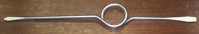
- 08.01.2010: Motor controller, Siemens G110, reprogrammed for higher wind
pressure range. The settings for the volume controller have to be adapted
in all already existing code and file material accordingly. HarmO now has
a very high dynamic range, but caution is required with high wind pressures
as leaks can occur. The default settings in GMT have been updated.
- 11.01.2010: Failure in the back swell solved: a 10x enlarging lens was left
under the flap by the tuner...
- 13.01.2010: Motor controller needs better programming: now it gives error
F910 at sudden changes of wind pressure.
- 17.01.2010: Apparently there must be a firmware bug in the implementation
of controller 66 (motor on/off). To be checked with Johannes.
- 20.01.2010: considering the design of a sensor mechanism for the swells.
Pepperl+Fuchs sensors appear to be a good choice for sensing the closed position
of the swells.
- 23.01.2010: PIC firmware programming session for the windvalve stepper (ctrl.1)
with Johannes Taelman. Now this works pretty well. Maximum speed is about
4 times a second for the entire movement trajectory. The ghost beaters still
have to be implemented.
- 24.01.2010: Thorough test and debug session. We encountered still inconsistencies
in the workings of ctrl.66.
- 25.01.2010: A
note on tuning reeds in reed organs, by Troy Rogers,
- 27.01.2010: Replacement reeds ordered for the untunable reeds in de 4' register.
- 31.01.2010: Extensive tests of the windslide. Slipping can occur, so we
may need to add some kind of position sensor.
- 12.02.2010: <HarmO> is off to Hasselt for the Boink! festival there.
- 15.02.2010: Crash reported in Yvan piece in Hasselt. On return, Harmo was
o.k.. What's the trouble, whats the cause?
- 17.02.2010: Minor repair required on the subbas valves: if struck too hard,
they often do not fall back in place.
- 21.02.2010: Waiting in vain for Johannes to fix some bugs and get the poltergeist
working...
- 27.02.2010: Debug session with Johannes on the new midi-parsing code section
in the midihub and pulse board PIC's. The start-up problem seems to be reproducible
and may have to do with memory initialisation of the PIC. It has been demonstrated
that it is not the midi flow itself that causes the erratic behaviour. The
PIC's seem to reset automatically under certain as yet undetermined conditions.
This is problematic since it also means that the PIC then forgets the position
of the swell controllers.
- 13-18.03.2010: Work on interactive code for the demo at the Jazz & Sounds
festival. Loss of controller 66 signal is still a recurrent problem.
- 19.03.2010: The dented wheel got loose from the motor axle and needed a
repair. After this, controller 1 for the windslide will be functional again.
- 22.03.2010: HarmO demonstrated at Bijloke, Jazz & Soundsfestival
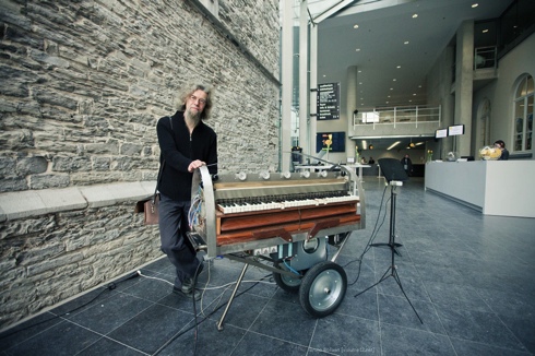
- 26.03.2010: Work on the interactive code for tomorrows concert with clarinetist
Daniel Pastene.
- 22.05.2010: Revision of the firmware for the midihub board PIC controller.
Hopefully we solved the bug in the quite unreliable startup, most noticeble
with the implementation of ctrl 66. Though this board is still programmed
in C, we believe assembly (or... Basic) to be much more reliable...
- 01.07.2010: Harmo seems to work reliably now, but the Poltergeist is still
not implemented in the PIC code.
- 09-10.10.2010: Harmo plays on the opening of the STAM museum on the Bijloke
campus: 12700 visitors...
- 11.10.2010: Basic proves to be a much tighter programming language than
C for our PIC controllers. The Proton+ compiler produces a lot tighter and
more efficient code than Microchip's own C compiler.
- 10.11.2010: Reconsidering the firmware coding for the windslide motor.
- 30.11.2010: Redesign of windslide motor circuitry, using a separate PIC
controller and at least one position sensor. This PIC can also take over the
control for the ghost beaters
- 02.12.2010: Small ferromagnetic hooks mounted on the edges of the windvalve
slider such that we have something to sense for our NAMUR proximity sensors.
Pepperl+Fuchs NAMUR sensors mounted on two small blocks of hardwood. These
will be glued on the side of the windchest such that they can sense the endpositions
of the slide
- 23.11.2012: White GU10 socket bulb replaced with Verbatim 6.5W LED.
23.02.2015: New circuit and PCB designed and drawn for the radial compressor
motor controller.
And here is the new circuit drawing: 
- 24.02.2015: Etching , drilling and soldering of the new motor control circuit
board. This is the connection diagram for the Sinamics motor controller:
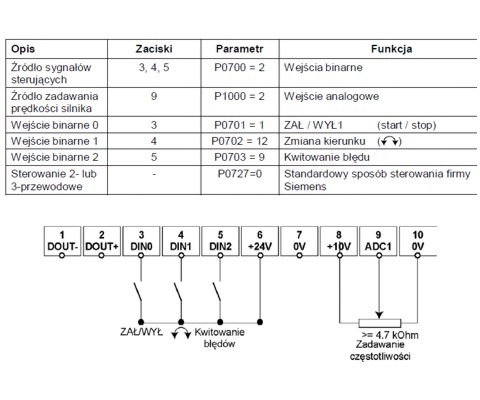
- 25.02.2015: Writing and testing of the motor control firmware, with build-in
intelligence. Here is the source
code. (Proton compiler).
- 26.02.2015: Start mounting of the new motor control board on the chassis.
- 27.02.2015: Test session with the new motor control board. Close inspection
of the swells revealed broken hinges. In fact, a piece of glued-on textile
ribbon was used as hinge material here. We will need to replace this with
something more durable.
- 28.02.2015: Bug removed in the hardware of the motor controller PIC: the
opamp should not be inverting! Corrected on the board and in the circuit drawing.
Further tests under GMT.
- 13.09.2018: <HarmO> found no longer functioning. Apparently something
goes wrong with the port assignments.
- 16.09.2018: Harmo replaces Krum now. Everyhing works fine, except the 'intelligent
motor control'... Setting ctrl.67 to 1 and steering the wind with commands
solves the problem for now. We have to continue the work on the motor microcontroller
firmware.
- 16-18.04.2020: The corona madness gives us some time to have a look again
at the motor control firmware for <harmO>.
- 27.11.2020: Rehearsing with Emilie De Vlam for a corona-lockdown streaming
on december 3th.
- 04.04.2021: Motor control PIC reprogrammed. There is still ample space for
refinements.
- 05.04.2021: Apparently we never got to improve the firmware on the hub board...
It's about time to get this done... We might consider to change the swells
completely, by using DC motors and sensors. The steppers we had are too noisy
in any case.
- 27.11.2022: Revision of the motor control firmware. Now using 10-bit PWM
at 39kHz. Efficiency greatly improved.
- 12.01.2023: due a a leak in our roof (a consequence of the budget cuts we
had to undergo as 'diversity' is not our prime concern...) , we suffered from
rust on the tremulant mechanism... It's function is now severely compromized.
To be done:
- coding for the ghost beaters mapped on notes 0 and 1
- PWM implementation for the yellow led's such that they can be dimmed.
- replacement of the non-speaking reeds in the highest octave of the 4' register.
- re-write the PIC firmware for the windslide (Controller #1) and throw in
end position sensors.
- wiring clean-up.
Literature and bibliography:
- Analog Devices: AD820 Datasheet
Sears, Roebuck and Co., "The reed organ", Chicago, 1910
- Barbara Owen, "Reed organ", in: 'The new Grove dictionary of musical
instruments', ed. Stanley Sadie, Macmillan Press Ltd, NY 1984
- Robert F. Gellerman, "Gellerman's International Reed Organ Atlas",
ed. Vestal Press. (ISBN 1-879511-34-7)
- Bowers, David Q., "Encyclopedia of Automatic Musical Instruments",
ed. Vestal Press, New York 1972 (ISBN 0-911572-08-2)
- Raes, Godfried-Willem, "Expression
control in automated instruments", 2010/2022
- Raes, Godfried-Willem, "Logos @ 50, het kloppend hart van de avant-gardemuziek
in Vlaanderen" (ed. Stichting Kunstboek, Oostkamp, 2018)
- http://www.perfectthird.com/harmonium_repair.htm
- Rogers, Troy, "A note on tuning reeds
in reed organs" (2010)
- Siemens Gmbh, 'Sinamics Motor
Controller Manual' (2005)
- Siemens Gmbh, 'Sinamics Motor Controller
G110 parameter list. (2005)
Robody picture with <HarmO>
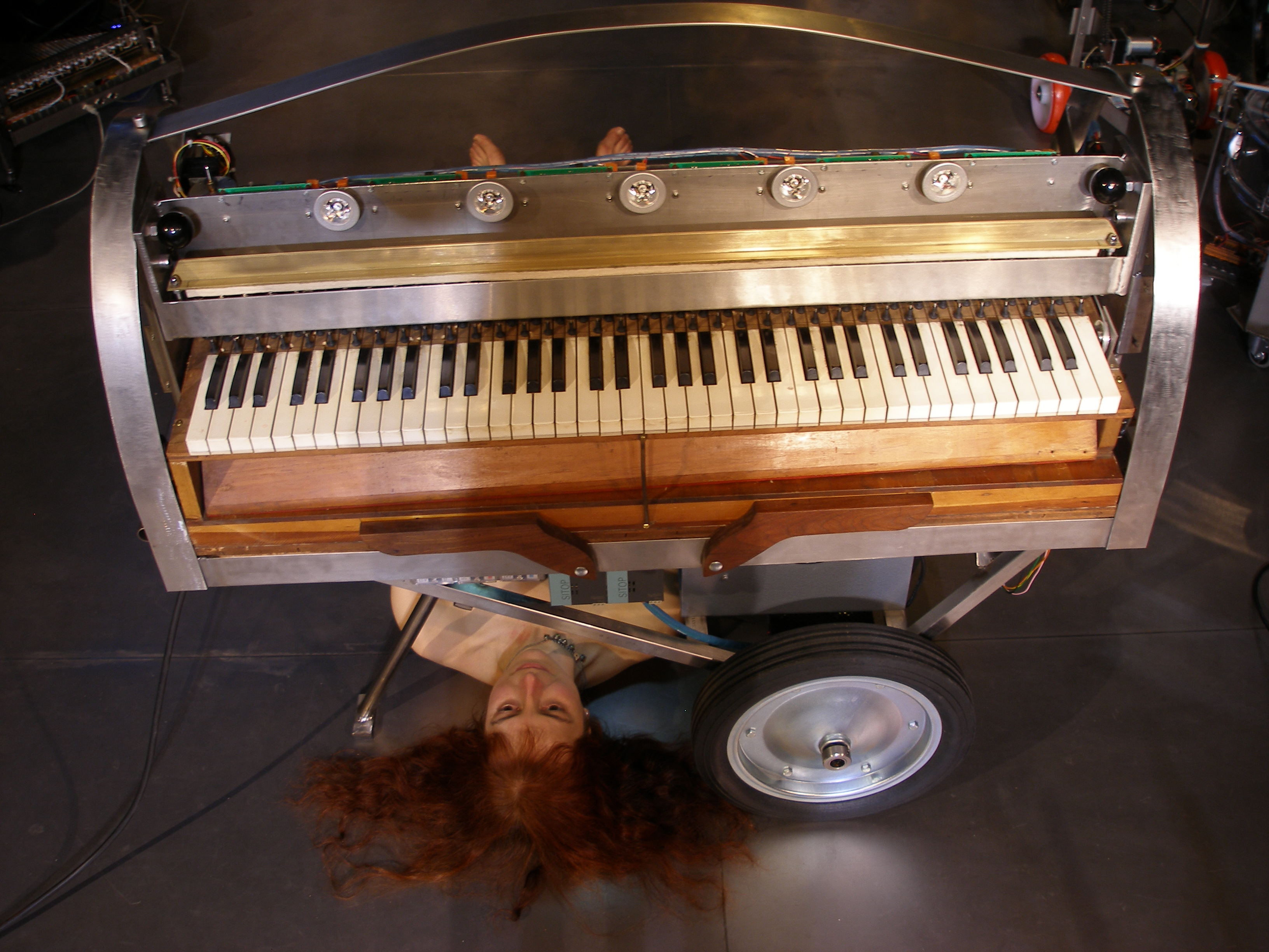
last update: 2026-07-17
by Godfried-Willem Raes