|
|
|
<Chi>
automated orchestral chimes
dr.Godfried-Willem
RAES
2016
|
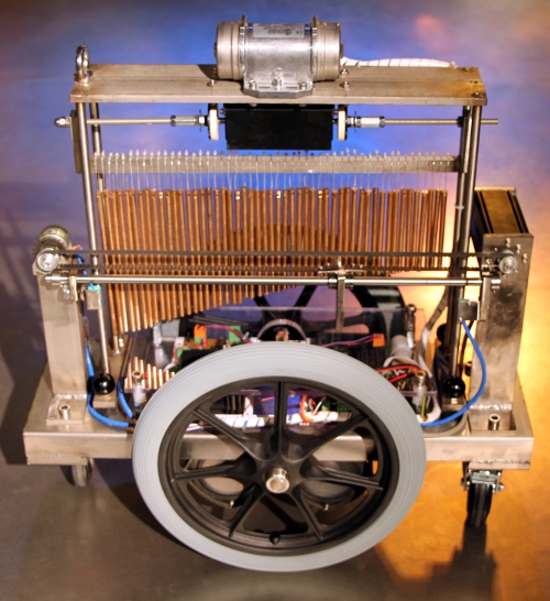
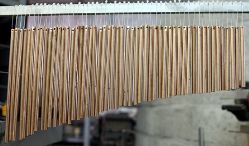
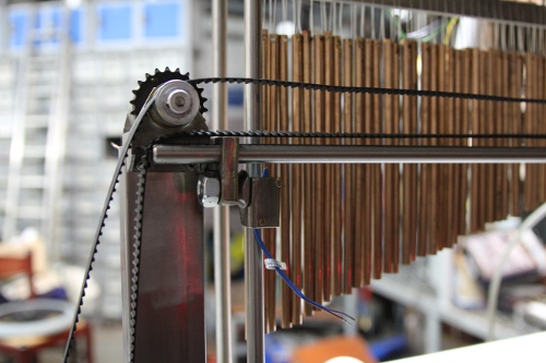
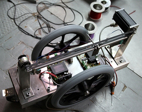
Orchestral chimes are a relatively new addition to the gamut of orchestral
percussion instruments. They entered our orchestras in the early seventies of
the 20th century. Generally they are made from aluminum staff material, in rods
of ca. 6 to 8 mm in diameter. The number of chimes in a set ranges between 28
and up to 42. One of the main considerations in the design of this robot was
to build it from materials we had in stock. The reason being that in the period
of its conception and construction, we suffered from very serious insecurities
with regard to the funding of the Logos Foundation by the Flemish government.
So we had to avoid any kind of extra expenses.
From an acoustical point of view, orchestral chimes behave as freely vibrating
rods. For our instrument we used bronze, mainly for the greater clarity of sound
and the much larger ultrasonic spectrum. The fundamental resonant frequency
of these rods is inversely proportional to the square of the length of the rod:
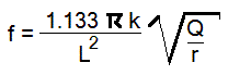 With: f= fundamental frequency
in Hz, L= length of the rod, k=diameter of the rod, Q= modulus of elasticity,
r= density of the material. (Olson, p.77). The overtones are a non-harmonic
series, given in the literature as:
With: f= fundamental frequency
in Hz, L= length of the rod, k=diameter of the rod, Q= modulus of elasticity,
r= density of the material. (Olson, p.77). The overtones are a non-harmonic
series, given in the literature as:
- f1 = 2.756 f0
- f2 = 5.404 f0
- f3 = 8.933 f0
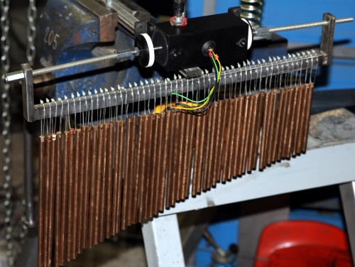
Excitation of the chimes can be achieved in three different ways:
- 1.- by shaking left/right of the entire chime assembly. This is implemented
with a large bi-directional solenoid.
- 2.- by vibrating the assembly in a front/back motion. This is implemented
with a motor driven vibrator. This gives a quite rich sound cloud.
- 3.- by striking the rods with a metal bar left to right and reverse. This
is implemented with a servo motor driven linear motion mechanism. This gives
the traditional 'glissando effect'.
All different modes of excitation can be combined freely.
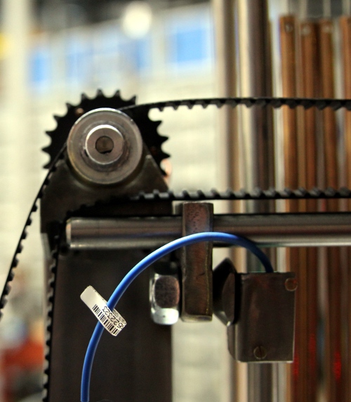
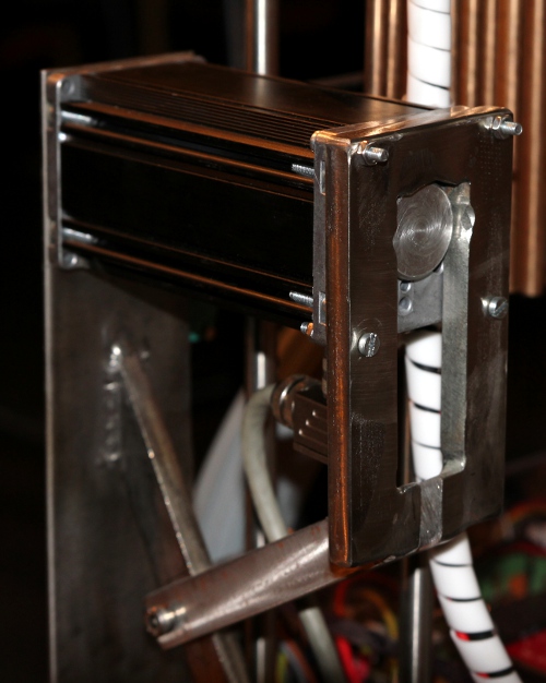
For the linear motion, we used a Dunkermotor, type BG65x50SI, rated for 24
V operation. Nominal rpm for this motor is 3090, as this, if it were to drive
a threaded rod (M10 thread) directly, would lead to a pretty slow linear motion
in the order of 10 seconds for the full glissando, we used a dented belt mechanism
between the motor and the rod. Proximity sensors are mounted on both ends of
the striking mechanism. The motor can be speed controlled and can move to the
left or to the right. However, jumping from one spot to another is not possible.
On reaching either end position, the motor will stop automatically. It is up
to the user to reverse the direction of rotation. A command to make the motor
move and go over and back between two given positions is also implemented. On
cold boot, the robot will always perform a calibration and than return to the
extreme left position. Users should never move the motorised slide by hand,
as doing this will invalidate the calibration. Note that fast changes of motor
speed may cause motor stalling and should be avoided.
We did not provide in a damping mechanism for the chimes. Thus users are warned
that the sound may go on for much longer than the actual duration of the excitation.
Just like in the case of our <Tinti> robot, a nice and original feature
here again is that the sounds it produces are extremely high pitched and their
spectral components extend well into the ultrasonic range. We measured sound
pressure levels up to 114 dBC in the frequency range between 25 and 35 kHz.
(Note that the dBA scale cannot be used, as this is corrected for the characteristics
of the human ear). This opened a wealth of musical possibilities when used in
combination with our ultrasound based
invisible instrument technology. In fact, the sensors we developed capture
the ultrasonic components of the chimes very well and, due to the demodulation
circuitry, can be brought into the audible range and even be modulated through
gesture and movement. Quite magic in fact.
The idea behind the technology being very similar, the implementation for <Chi>
however, came out quite different than what we did for <Tinti>. First
of all, we used the PIC microprocessor on the midihub board to generate ultrasonic
frequencies in the range 16 kHz to 38 kHz. The frequency can be modulated on
the fly using pitch bend commands. The amplitude of the ultrasonic carrier signal
used for demodulation can be controlled with controller #8. However, other than
in <Tinti>, here we feed the ultrasonic carrier frequency directly into
a multiplier circuit, thus circumventing the problem of finding suitable wide
band ultrasonic transducers. Thus we perform frequency demodulation on the ultrasonic
spectral contents of the chimes, transposing them into the audible range. If
this feature is enabled on the <Chi> robot, the audible result is that
all difference tones between the carrier frequency and the ultrasonic components
of the chimes become audible through the build-in speakers. Although this robot
has indeed a pair of loudspeakers, it should not be considered an electronic
instrument at all, as all sound produced is inherently acoustic. By modulating
the carrier frequency, pitch shifts of the chime sounds become possible. The
effect is quite mesmerizing.
A final remark: as this robot makes use of ultrasonic frequencies it may show
interference with our ultrasound based gesture sensing technology, as the acoustic
frequencies used could interfere with the invisible instrument used for gesture
recognition. So composers should make sure they test their concept thoroughly
before attempting to use <Chi> in our sonar based gesture-interactive
environment. If our radar equipment (PicRadar, Quadrada etc...) is used at the
other hand, no interference can occur as its working principle is based on microwaves
and not on sound. The same problem with interference can also happen if the
<Chi> robot is used together with the <Tinti> robot, as <Tinti>
is capable of emitting ultrasound as well.
Only when integrated in the context of our robot
orchestra with its wealth of varied sensor systems allowing full interactivity
with gesture and audio, this automate will become a true robot. That's after
all were its destination is to be sought.
Midi Mapping and implementation:
This is the ambitus for the instrument: 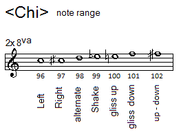
Midi channel: 9 (10 if counting 1-16).
- Note 96: the bronze tine assembly will move to the left. The force is controlled
by the velocity byte.
- Note 97: the bronze tine assembly will move to the right. The force is controlled
by the velocity byte.
- Note 98: the bronze tine assembly will move in alternating directions. The
force is controlled by the velocity byte. If a repetition rate is programmed
using the key pressure command, the over and back movement will continue until
a note off command is received.
- Note 99: The vibrator will be activated. The intensity of the vibrator is
steered by the velo byte. Key pressure can be used for automated repeats.
- Note 100: the motor will run in clockwise direction ( the sledge moves to
the left then) and play the downwards glissando as long as the note stays
on. When the left end position is reached it will automatically stop. The
speed of the movement is controlled by the value of the velocity byte. The
left end position can be controlled with controller #74.
- Note 101: the motor will run in counter clockwise direction (the sledge
moven to the right) and play the upwards glissando as long as the note stays
on. When the right end position is reached it will automatically stop. The
speed of the movement is controlled by the value of the velocity byte. The
right end position can be controlled with controller #75.
- Note 102: the motor will move over and back between the positions set with
the controllers #74 and #75. If these controllers are not sent, the movement
will use the entire trajectory. The maximum speed of the movement after the
ramping is controlled with the value of the velocity byte. Whilst the motor
is running, the speed can be changed using the key-pressure command.
- Note 103: will activate the brake. The braking force can be controlled with
the velocity byte. Braking also stops the motor. On reception of a note off
for note 103, the clutch will release.
- Note 120: Red Lite, the velo byte steers the flashing frequency
- Note 121: Red Lite, the velo byte steers the flashing frequency.
- Note 122: Tungsten lights, left and right together. The brightness can be
steered with the velocity byte. Flashing is implemented with the key-pressure
command.
Controller 7: Volume control for the ultrasonic receiver and amplification.
Setting this controller to zero will mute the amplifier.
Controller 8: Level for the ultrasonic carrier wave. This works by PWM on the
carrier wave (range 0-50%). The effect is not spectacular, but using lower settings
helps to reduce the spikes in the bell sounds. With a setting to maximum, the
duty cycle will be 50% and the waveform symmetrical and reasonably sinusoidal..
With low values for this controller, leak through of the carrier frequency,
if this is set to values within the human perception range, can be minimized.
Controller 30: sets the repetition rate for all components that have auto-repeat
implemented, including the lights.
Controller 31: can be used to shift the frequency range
of the carrier frequency in chromatic steps as shown in this table:
| Value |
base frequency |
midi note |
note name |
| < 39 |
21096 Hz |
136 |
E |
| 39 |
2489 Hz |
99 |
Eb |
| 40 |
2637 Hz |
100 |
E |
| 41 |
2794 Hz |
101 |
F |
| 42 |
2960 Hz |
102 |
F# |
| 43 |
3136 Hz |
103 |
G |
| 44 |
3322 Hz |
104 |
G# |
| 45 |
3520 Hz |
105 |
A |
| 46 |
3729 Hz |
106 |
Bb |
| 47 |
3951 Hz |
107 |
B |
| 48 |
4186 Hz |
108 |
C |
| 49 |
4435 Hz |
109 |
C# |
| 50 |
4698 Hz |
110 |
D |
| 51 |
4978 Hz |
111 |
Eb |
| 52 |
5274 Hz |
112 |
E |
| 53 |
5587 Hz |
113 |
F |
| 54 |
5920 Hz |
114 |
F# |
| 55 |
6272 Hz |
115 |
G |
| 56 |
6644 Hz |
116 |
G# |
| 57 |
7040 Hz |
117 |
A |
| 58 |
7458 Hz |
118 |
Bb |
| 59 |
7902 Hz |
119 |
B |
| 60 |
8372 Hz |
120 |
C |
| 61 |
8870 Hz |
121 |
C# |
| 62 |
9397 Hz |
122 |
D |
| 63 |
9956 Hz |
123 |
Eb |
| 64 |
10548 Hz |
124 |
E |
| 65 |
11175 Hz |
125 |
F |
| 66 |
11840 Hz |
126 |
F# |
| 67 |
12544 Hz |
127 |
G |
| 68 |
13289 Hz |
128 |
G# |
| 69 |
14080 Hz |
129 |
A |
| 70 |
14917 Hz |
130 |
Bb |
| 71 |
15804 Hz |
131 |
B |
| 72 |
16744 Hz |
132 |
C |
| 73 |
17739 Hz |
133 |
C# |
| 74 |
18794 Hz |
134 |
D |
| 75 |
19912 Hz |
135 |
Eb |
| 76 |
21096 Hz |
136 |
E |
| >76 |
21096 Hz |
136 |
E |
If any controller value setting in the midi note range higher than note 127
is send (controller values > 67) , the blue LED on the demodulation board
will light up. The actual frequency generated will always be the base frequency
with the 14-bit value send with the pitch shift command added. The default value
for this controller is 76. The formula for calculating the frequency of the
emitted sound is: f = (2489 * 2^((CC31 - 39)/12)) + (pbmsb * 128) + pblsb, wherein
CC31 is the setting for controller 31 within the limits 39 to 76, pbmsb the
7-bit value sent with the pitchbend command and pblsb the low 7-bit value of
the pitchbend command.
Controller 65: Mute switch for the amplifier section. Value 0 mutes the amplifier,
any other value will turn it on.
Controller 66: Robot on/off switch. Sending this controller with value zero
will power down the robot and reset all controllers to their default value.
The glissando motor will return to its default extreme left position if it wasn't
there already. The amplifier will be muted.
Controller 70: Calibrates the movement motor position and brings it to a left
position. This command should only be sent on a full stop of all motors, i.e.
no other midi motor related commands should be sent during this calibration.
The parameter can be any non-zero value. This calibration also takes place automatically
after a cold start of the robot. Do not use this controller in any sequenced
composition. If the motorised sledge has been moved by hand with the robot turned
on, this command must be send in order to recalibrate the positions.
Controller 71: implemented for hardware debugging: Motor OFF. Do not use this.
Controller 72: implemented for hardware debugging. Absolute
run clockwise. Do not use this.
Controller 73: implemented for hardware debugging. Absolute
run counterclockwize. Do not use this.
Controller 74: sets a left side start or end position for the motor carriage.
By default this controller is set to 0, corresponding to extreme left.
If a value is given larger then the setting for controller #75, the robot will
correct this and set the controller to the value for controller #75 minus one.
On reception of this controller the motor will
move to the position given by the value of the parameter.
Controller 75: sets a right side start or end position for the motor carriage.
By default this controller is set to the extreme right if calibration was performed.
This setting may be smaller than 127. If a value for this parameter is send
smaller then the value for controller #74, the robot will correct this and will
set the controller to the value for controller #74 + 1. The setting for the
right side position must always be larger then the position for the left side.
The minimum value for this controller is 1.
Controller 76: sets the ramping speed for motor acceleration. Default startup
value = 64. Minimum value =1. Note that ramping is never applied to slowing
down.
Controller 123: All notes off, preserving controller settings and motor position.
The motor will be halted.
Pitch bend: used to modulate the ultrasonic carrier wave. (All 14 bits are
used as a unipolar unsigned 14 bit value). The frequency can be controlled between
basefrequency (by default 21096 Hz) and basefrequency + 16384. So the upper
limit for the ultrasonic frequency is 37480 Hz. With CC31 set to 39, the lower
limit is 2489 Hz.
Status indicators on the PCB's:
- Ultrasonic microphone board:
- The vertical LED-bar serves as a VU meter.
The lowest bar
should never lite up, as this indicates saturation of the pre-amp.
- Ultrasound demodulation board:
- Red LED: Processor watchdog. This LED flashes on/off at a rate of ca.
0.75 Hz
- Blue LED: This led will be on as soon as the demodulating signal is
ultrasonic (> 20 kHz)
- Green LED: This LED follows the power on/off status. When controller
#66 is set to ON, this LED will be on.
- Yellow LED: If this LED is off, the amplifier is muted. If on, the audio
system is turned on. The LED follows the status of controller #65.
- Motor controller board:
- Red LED: Processor watchdog. This LED flashes on/off at a rate of ca.
0.75 Hz
- Blue LED: Flashes as the position of the motor driven slide changes.
- White LED: this LED is always on when the 5V processor voltage is present.
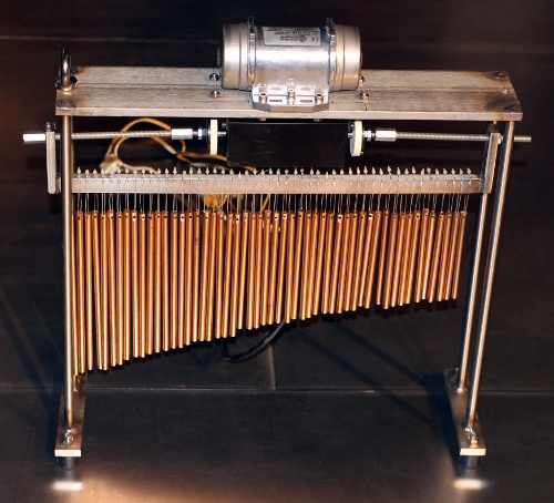
Technical specifications:
- size: width 560 mm, height 500 mm, depth 200 mm
- weight: 40 kg
- transportation: needs a flightcase.
- power: 230 V ac / 165 W (peak, normal playing less than 50 W)
- Ambitus: untuned.
- control: MIDI-input, 3 MIDI-Thru, differential. (UDP/IP Ethernet port to
be implemented later)
- loudness: <=98dBA at 1m distance.
- Insurance value: 11.500 Euro
Design and construction: dr.Godfried-Willem
Raes
Collaborators on the construction of this robot:
- Mattias Parent ( mechanics, PCB drilling, workshop assistant)
Music composed for <Chi>:
Godfried-Willem Raes:
'Namuda Study #60 : The Passion of Chi' (2016)
Kristof Lauwers: new piece including Chi (2016)
Kristof Lauwers: 'Picradar Study for Chi' (2016)
Pictures taken during the construction in our workshop (in chronological
order):


Robodies picture with <Chi>:
[waiting for nude model candidates]
Construction & Research Diary:
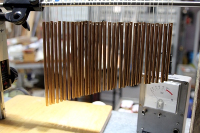
- 28.02.2016: Start construction of a set of chimes from bronze staff material.
- 29.02.2016: Measurements on the ultrasonic power spectrum performed.
- 01.03.2016: 43 tone rods cut and drilled. Lengths varying between 240 mm
and 120 mm. This gives a range of four octaves.
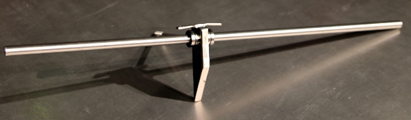
- 02.03.2016: design of a suspension bar. Distance between rods taken as 9
mm. This gives us a 1 mm space between the rods. Experiments carried out with
a large fan in order to find out in how far it would be possible to agitate
the chimes with wind. Result: possible, but at the required wind-speed, the
fan becomes way too noisy.
- 03.03.2016: Experiments with a motor driven vibrator (Italvibras). Number
of chimes augmented to 51. Construction of the suspension staff: stainless
steel 500 x 10 x 25, with slots 0.8 mm wide on 9 mm distance between slots.
First tests with a Laukhuff bi-directional solenoid, same type as used for
<Klung>.
- 04.03.2016: Construction of the upper mounting plate: stainless steel 500
x 100 x 10. This plate holds both the bi-directional solenoid as the vibrator
motor. Welding works: vertical poles are 450 mm long, 12 mm diameter, these
are strongly welded on the upper plate as well as on the base strips (30 x
10 x 160).
- 05.03.2016: Research and measurement of the ultrasonic spectrum of the chimes.
Design of a motorized striking rod for linear motion. Here we could use an
M10 threaded rod with a high nut. The speed is 1.5 mm / rotation. Hence for
the 50 cm trajectory, 333 rotations are required. If we use a 3000 rpm motor,
the whole trajectory would take about 10 seconds.
 Not
really fast... Anyhow the use of a DC motor seems mandatory here. A stepper
would be way to noisy here.
Not
really fast... Anyhow the use of a DC motor seems mandatory here. A stepper
would be way to noisy here.
- 06.03.2016: Experiments with a Dunkermotor servo, type BG65x50SI.
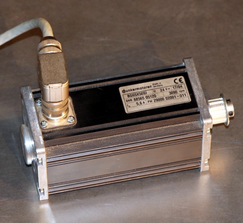 Maybe a bit overkill, taking into account the price being far over 1000 Euro...
First version for a control board using an 18F2525 microcontroller. In any
case, two microcontrollers will be required as we are in need of at least
3 PWM channels. For the end-sensors we can make use of two Pepperl-Fuchs NAMUR
proximity sensors, type NJ 2-V3-N. These can be powered from 5V directly,
although this is lower then the 8.2 V after the NAMUR specification. We used
then in earlier robots such as <Korn> as well.
Maybe a bit overkill, taking into account the price being far over 1000 Euro...
First version for a control board using an 18F2525 microcontroller. In any
case, two microcontrollers will be required as we are in need of at least
3 PWM channels. For the end-sensors we can make use of two Pepperl-Fuchs NAMUR
proximity sensors, type NJ 2-V3-N. These can be powered from 5V directly,
although this is lower then the 8.2 V after the NAMUR specification. We used
then in earlier robots such as <Korn> as well.
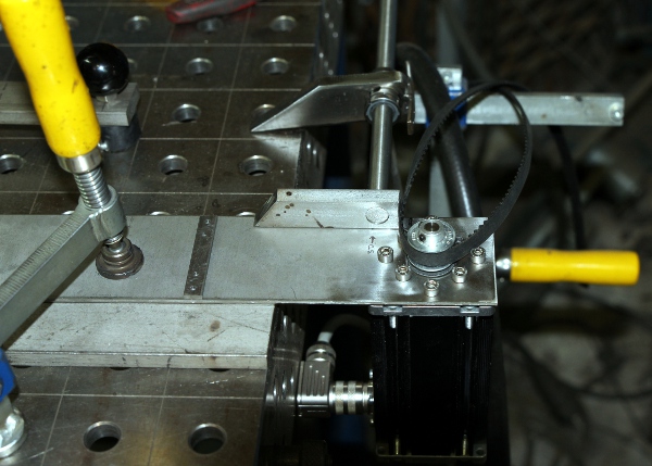
- 07.03.2016: Alternative design worked out for the horizontal movement: a
spindle, 12 mm, with a linear ball bearing sliding over it and driven via
a dented belt would allow for movement speeds at least a factor 20 faster
than in the threaded rod approach.
 The
Dunkermotor can still be used in this design. Detailed technical drawing of
the mechanical construction, scale 1:1. First prototype of the linear motion
mechanism welded in stainless steel.
The
Dunkermotor can still be used in this design. Detailed technical drawing of
the mechanical construction, scale 1:1. First prototype of the linear motion
mechanism welded in stainless steel.
- 08.03.2016: Cutting of the bottom mounting plate. Delivery of 24 V / 6 A
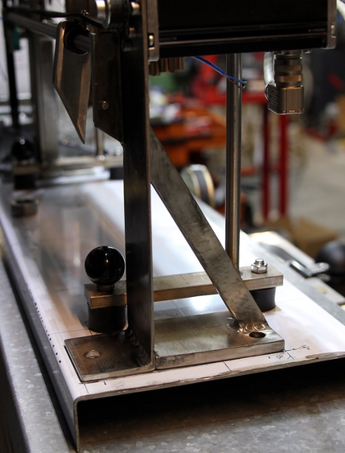
power supply and solid state relays from Farnell. Welding of the slide assembly:
The distance between
bottom plate and center of excitation point for the chimes determined and
fixed to 220 mm. For the non-motorised side of the spindle we mounted a solenoid
operated clutch with ball bearings. It's a part we recycled from an old photocopier.
It will allow us to perform easy braking in the movement.
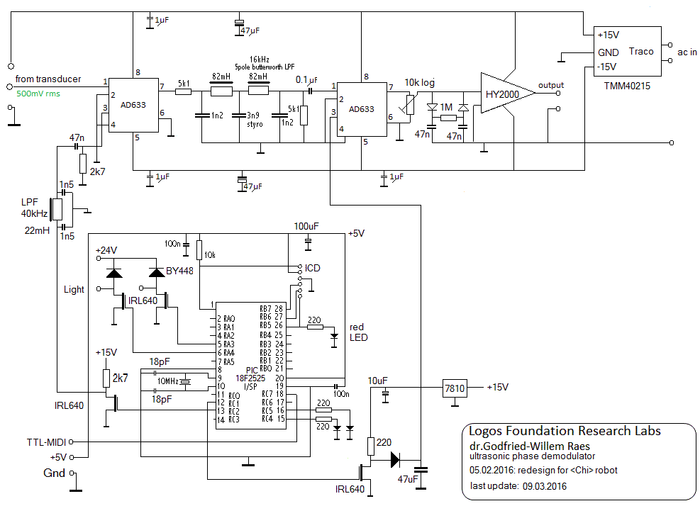
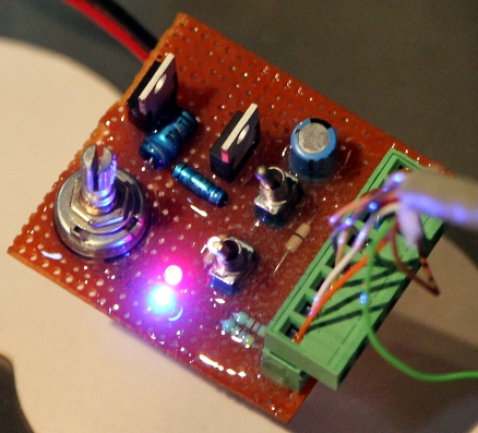
- 09.03.2016: Design of the ultrasonic demodulation board. There are some
major improvements in this design as compared to what we did for <Tinti>.
For the volume control, here we are using a second AD633 multiplier wired
as a VCA. Start of the design of the PCB for this circuit.
- 10.03.2016: Design for the ultrasound demodulation board finished. No response
yet from ILP with regard to our order. Are they going out of business?
- 11.03.2016: Design of the hub and motor control PCB. Welding works on the
motor stand. Calculation
of a suitable wheel base.
- 12.03.2016: Looks like ILP Electronics Ltd. is out of business. This means
we have to redesign the PCB and circuit for the demodulation board. The TDA7264
looks like an easy candidate for the substitution. It's a 2-channel chip rated
for 2 x 15 W. This could be the new circuit:
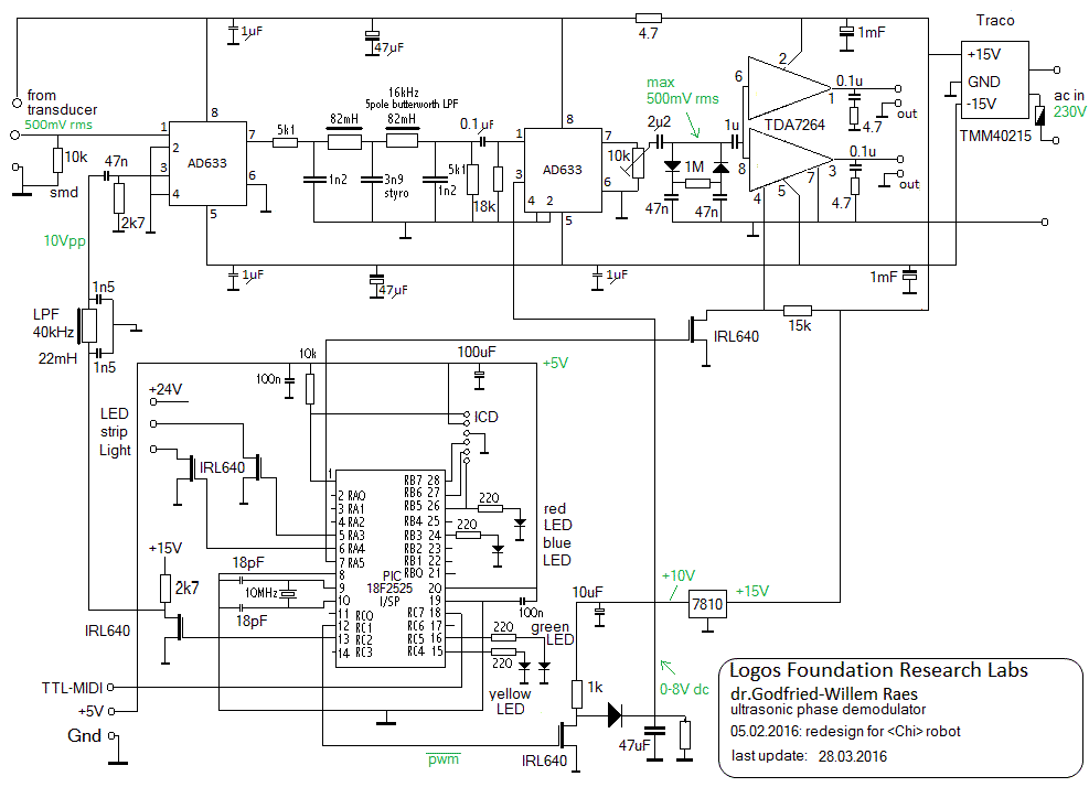 An extra feature here is the addition of a mute circuit, controlled by a PIC
port. Also, since it's a 2-channel chip without facilities to use it in bridge
mode, we will connect two small loudspeakers on the outputs. PCB board for
this design drawn out. This is ready for production now. TDA7264 chips ordered
from Farnell.
An extra feature here is the addition of a mute circuit, controlled by a PIC
port. Also, since it's a 2-channel chip without facilities to use it in bridge
mode, we will connect two small loudspeakers on the outputs. PCB board for
this design drawn out. This is ready for production now. TDA7264 chips ordered
from Farnell.
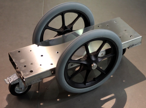
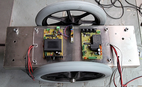
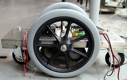
- 13.03.2016: Construction of the wheelbase. Axle for the 400 mm diameter
spoke wheels is 20 mm. The smaller pivoting wheels have 120 mm diameter and
a building height of 160 mm. Drawing and construction of the mounting plate
for the two SMPS modules as well as the IEC power entry with switch. This
plate mounts with four M8 bolts to the main chassis.
- 14.03.2016: Design and construction of the mounting plate for the transducers.
This plate connects to the main chassis with 4 countersunk M8 x 16 bolts and
nuts on the backside of the robot. Start wiring of the power supply assembly.
Welding of the wheelholder plates to the main chassis. Mounting of the wheels.
Test of the movement.
- 15.03.2016: Bulb sockets mounted on chassis using Parabond. The TDA7264
audio amplifier chips came flowing in from Farnell. Exposure, development
and etching of the PCB's. Start soldering of the hub and motor control board.
Around midnight we had both PCB's assembled...
- 16.03.2016: Hardware testing and checking. Demodulator board thoroughly
tested and firmware version 1.0 written and debugged. Some minor bugs in the
hardware solved. Testcode added to our GMT software. <Chi> is fully
implemented now as a member of the robot orchestra. A pair of new encapsulated
squawkers digged up and tested. Philips AD50600/SQ8. Here is a picture:
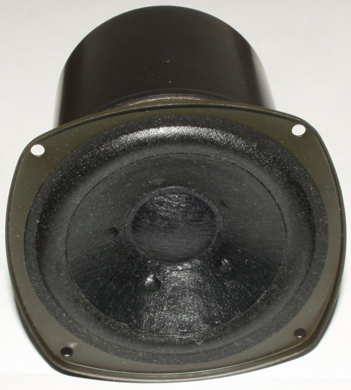 Real
vintage items as they were produced in 1972. They have been living on our
shelves since then... Eight standoff tubes cut from brass, 102 mm long. Mounting
will be done with M4 threaded rods.
Real
vintage items as they were produced in 1972. They have been living on our
shelves since then... Eight standoff tubes cut from brass, 102 mm long. Mounting
will be done with M4 threaded rods.
- 17.03.2016: Firmware for the demodulator board improved. Now version 1.1.
Mounting of the loudspeakers on the backplate. Cutting of the polycarbonate
mounting plate for the PCB's and the ultrasonic microphone. Start wiring of
the components mounted under the main chassis plate.
- 18.03.2016: Mounting of the loudspeaker assembly. Mounting of the PCB's
on the polycarbonate plate. Mounting of the motor mechanics on the main chassis.
Start wiring of the boards. This is the wiring diagram for the motor and hub
board:

- 19.03.2016: Further wiring of the <Chi> robot. Running out of 2-pole
Weidmueller connectors as well as shrink tube... Missing components ordered
from Farnell. Start writing the firmware for the motor and movement control
board.
- 20.03.2016: a full day of debugging the firmware for the motor board. Not
working yet!
- 21.03.2016: Set rings placed on the horizontal slide, one side flattened.
Further work on the motorboard firmware. Waiting for connectors and shrink
tubing, ordered from Farnell.
- 26.03.2016: Missing parts came in. Continuing work on the wiring. First
firing up of the robot... no smoke stacks in any case. Placement of the motor
AC capacitor (0.8uF/ 450V ac). Observing a nasty sound from the +5V/3A power
supply module on the hub board, the pitch changing with the load... This SMPS
module is produced by Vigortronics (VTX-214-015-105)... Shame over them.
- 27.03.2016: Further work on the assembly. First tests. US-demodulation board
fully saturating and even motorboating... The amplifier mute function works
well though... The lights do work as expected.
- 28.03.2016: Hardware debug of the demodulation board: pin 1 on the first
multiplier needs a DC return to ground: 10 k SMD resistor soldered on the
copper side. Same problem for pin 3 on the second multiplier: 18k resistor
soldered in. Motorboating problem remedied by placing a 4.7 Ohm resistor in
the +15 V line to the analog processing circuitry. Circuit drawing updated
accordingly. Sofar, this part of the robot seems to work quite well and as
expected. However we meet a problem with the +5 V/3 A power supply on the
motor board as it gives off sounds that get picked up by our microphone, get
demodulated and give a most disturbing varying pitch on the output... Testing
the motor board revealed following problems and deficiencies: the Laukhuff
solenoid works very well but needs rescaling of the velocities. The vibrator
motor works fine, but here also some rescaling might be required. The clutch
works fine, but has intermittent glitches. Either the connector is shaky,
or a bleeding resistor over the high voltage capacitor is required. Checks
revealed the connector (a French make...) was shaky. The Dunkermotor for the
slide mechanism remains fully dead... A deep going debug is required. The
position pulse counter works and the motor does not give an error signal.
The maximum DC voltage we get on the speed input is 7.8 V, well within specs.
- 29.03.2016: No matter what we try, the Dunkermotor (type BG65x50 SI, serial
number 88565 05120) remains dead. Would it have been too near to my welding
works? It does not give out an error message... We made a special manual control
board, but even with this it does not give a kick.
 At
startup, connecting the 24 V power supply, it draws some 280 mA current and
the shaft feels slightly locked. After a few seconds, the current falls back
to 20 mA and the shaft is fully released. Seems the Dunker motors are now
distributed by Eriks. Alternative 5 V SMPS power supply modules ordered from
Farnell. The Vigortronics type is trashworthy. Shaking mode and vibrator demonstrated
with the nicely working ultrasonic demodulation for Luk Vaes and Kristof Lauwers.
At
startup, connecting the 24 V power supply, it draws some 280 mA current and
the shaft feels slightly locked. After a few seconds, the current falls back
to 20 mA and the shaft is fully released. Seems the Dunker motors are now
distributed by Eriks. Alternative 5 V SMPS power supply modules ordered from
Farnell. The Vigortronics type is trashworthy. Shaking mode and vibrator demonstrated
with the nicely working ultrasonic demodulation for Luk Vaes and Kristof Lauwers.
- 30.03.2016: Work on the horizontal striking mechanism. Construction of a
polycarbonate cover plate. Fastening bolts and nuts. Visually it looks ready
(almost) now...
- 31.03.2016: Further work on the firmware: scalings for the Laukhuff solenoid
(now 10 to 60 ms), flashing for the tungsten lites implemented. 5 V Vigortronix
power supply module replaced with Traco Power type TML05105. This type fits
on the PCB. Autorepeat implemented also for the vibrator motor. Firmware flashed
and tested o.k. Polycarbonate upperplate bolted on with M10 x 40 bolts and
Epramid standoff's.
- 01.04.2016: Extensive testing under GMT control. Measurement of the loopspeed
-and thus the timing resolution- of the firmware in the motor control board:
11.7 us or 85.47 kHz. On heavy loads this value can reach a maximum of 14.2
us. (Tektronix TDS2024C measurement).
- 02.04.2016: Starting to write a Namuda Study demonstrating the wide range
of possibilities of the new robot.
- 03-04.2016: further application code development. Specific library functions
for <Chi> added to our g_file.dll library.
- 05.04.2016: Refinement of the slow PWM coding for the vibrator motor. Now
the pulse duration range is 20 ms to 100 ms, measured and verified on the
TDS2024C. Idealy, the motor control should take the phase of the mains voltage
into account. To avoid firmware complexity, it would be better to provide
in a microcontroller just to generate mains-voltage independent signals, 90
degrees phase shifted. Thus we could leave out the large AC capacitor form
the motor circuit and steer the motor with variable frequency directly.
- 06.04.2016: Further testing of useable ranges for controllers.
- 07-10.04.2016: Composition of the first gesture interactive piece for <Chi>"
'Chi's Passion'. Discovered that the vibrator can cause the midi connector
to come loose... If that happens, the robot is out of control of course...
- 17.04.2016: First rehearsals of 'Chi's Passion' with Dominica Eyckmans.
- 18.04.2016: Construction of a sturdy stud for the backside of the Dunkermotor,
as this one tends to resonate dangerously much when the vibrator is turned
on. The support mounts on the back motor flange with four M4 bolts. It is
clamped to the motor holder base with a single M6 x 40 bolt.

- 19.04.2016: Awaiting delivery of the new Dunker motor...
- 20.04.2016: Rehearsal for Chi's Passion with Dominica Eyckmans. The nylon
straps do tend to break off. We will have to round off the sharp edges on
the suspension slots.
- 21.04.2016: Premiere performance of Chi's passion as well as a new piece
by Kristof Lauwers, including Chi.
- 27.05.2016: The new Dunker motor came in. Problem: the mounting holes are
different from those on the original motor, so we will have to change the
holding chassis accordingly.
- 06.06.2016: Further work on the Dunker motor failure. Looks like the controll
signals for the Dunker motor BG65x50SI have to be 24V and not 5V TTL! (this
is contrary to what it says in the manual though). So, a modification on the
PCB will be required. We designed a simple logic level shifter as follows:
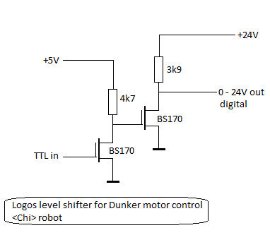 We mounted it
on a small piece of breadboard. The board accomodates two level shifters as
these are required for both the cw and the cww input to the Dunker motor.
First tests carried out with the original motor, as very likely there is nothing
wrong with it... and indeed, the motor is o.k. Now we can go on fine tuning
the firmware for the motor control...
We mounted it
on a small piece of breadboard. The board accomodates two level shifters as
these are required for both the cw and the cww input to the Dunker motor.
First tests carried out with the original motor, as very likely there is nothing
wrong with it... and indeed, the motor is o.k. Now we can go on fine tuning
the firmware for the motor control...
- 07.06.2016: Further firmware development on Chi: Motor controller.
- 08.06.2016: Finally got it working! Version Chi_Mot V1.1 flashed into the
motor PIC. Awaiting user feedback now.
- 09.06.2016: Lookup tables for Dunker motor speeds added in the firmware.
Firmware version is now V1.2 Adding ramping in the firmware implemented for
acceleration only, is still an open option. Chi demonstrated for our Berlin
guests.
- 10.09.2016: Working on motor firmware version 1.3, with ramping implemented.
Controller #76 added to make user control of ramping speed possible. Ramping
is only applied to speed up, as for slowing down and stopping, a mimimal ramping
function is implemented in the hardware (0.2s).
- 11.06.2016: Further debugging and smoothing of the motor control firmware/
- 12.06.2016: Firmware version 1.4 for the motor PIC flashed.
- 18.07.2017: <Chi> used in the orchestration of our Erik Satie 'Parade'
production.
- 24.07.2017: <Chi> added in the orchestration of 'Summer' in Godfried-Willem
Raes' Symphony #3.
- 23.10.2020: <Chi> gets an important role in our Ukiyo-E production.
- 22.01.2021: <Chi> found to be vandalized, despite our warnings: "The
placement of the midi I/O connectors behind the back wheel, is awkward. We
advize users to use an angled DIN connector here. Never lead the midi cable
through the wheel spokes." The reason for this warrning became very clear
now... Repair of the midi-hub board required.
- 23.01.2021: Midi hub board repaired and modified: now the midi-in cable
goes into the PCB vertically. To make this possible, we drilled a large hole
in the polycarbonate cover plate above the PCB's. Also we removed one of the
midi thru connectors, so now Chi only has two functional balanced midi thru
outputs.
- 23.06.2023: The hex-inbus bolts securing the dented drive wheel on the motor
came loose. This was the cause of irregular and erratic behavior of the slide.
Also the sensors were found to be loose. Tightening all bolts solved all reported
problems. Ultrasonic demodulation system checked and found o.k.
- 08.11.2023: Two tines got loose and fell out. We replaced the nylon straps.
<Chi> works fine again and joins in the performance of my 4th symphony.
TO DO:
- This robot became ready on june 12th 2016. However, it was already presented
to our audience, April 21st 2016 at the occasion of the Logos Robot Orchestra
concert that evening.
- Construction of a flightcase with a clamp for the tines.
Last update: 2023-11-08
by Godfried-Willem Raes
The following information is not intended for the general public nor for
composers wanting to make use of our <Chi> robot, but is essential
for maintenance and servicing of the robot by our collaborators. It also
might be useful as a source of inspiration for people that want to undertake
similar projects. Our designs are not copyrighted but placed into the public
domain, thus copying designs is allowed, provided the source is always explicitly
credited and referred to. Feedback is mostly welcomed.
Technical drawings, specs
and data sheets:
Power supplies:
- +5 V DC - 2 A (Logic, led-lights and microcontrollers, mounted on the
hub and motor control board. Traco Power, type TML05105)
- +15 V-0- -15 V DC - 1 A for ultrasonic demodulation circuitry and amp.
(Traco Power SMPS, type TMM40212) (mounted on the ultrasound and amplifier
board).
- +24 V - 6.3 A (SMPS XP-Power, type LCL150P24) [mounting: 4 M4 x 8 bolts]
- +48 V - 2.3 A (Sunpower SMPS, tpe SPS-S100-48) [mounting: 3 M3 x 6 bolts]
Bronze alloy used for the tone rods: Cu Pb 10 Sn, s.g.= 9.1 kg/dm3 (DIN
1716), ordered from Demar Lux bvba.
- Motorvibrator:
- Italvibras M20, Farnell order nr. 7035123, 22 VA - 230 V, phase shift
capacitor: 0.8 uF/ 450 V ac
- http://www.italvibras.it
- Linear motion:
- Dunker servo motor: BG65x50SI (24 V, 100 VA, 70-4000 rpm) [907 Euro,
purchased in 2003]
- dented drive wheels: CTB12037ALU
- dented belt: Gates powergrip 037 672 XL
- linear ball bearing: STAR Linear bushing 0612-012-10 (Deutsche Star
Gmbh, D-97419 Schweinfurt)
- spindle: Stainless steel 12 mm diameter, polished.
- end sensors: NAMUR, Pepperl-Fuchs NJ2-V3-N (read as analog voltages,
the output not being TTL compatible)
-
Bi-directional solenoid: August Laukhuff, kleiner trakturmagnet.
Ultrasound components:
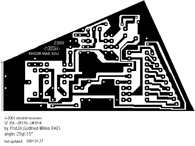
- Circuit drawing for the ultrasound receiver board (designed 2001):
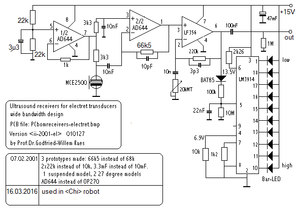
- The PCB for this circuit:
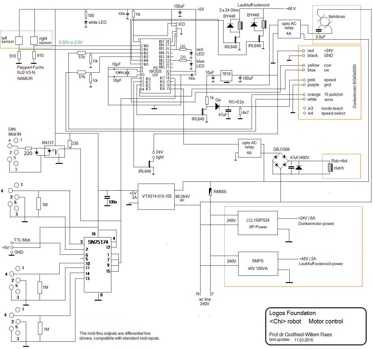
- Demodulator circuit:
- PCB for this board:
- Firmware for this board: Chi_US.bas,
hex dump for this firmware: Chi_US.hex
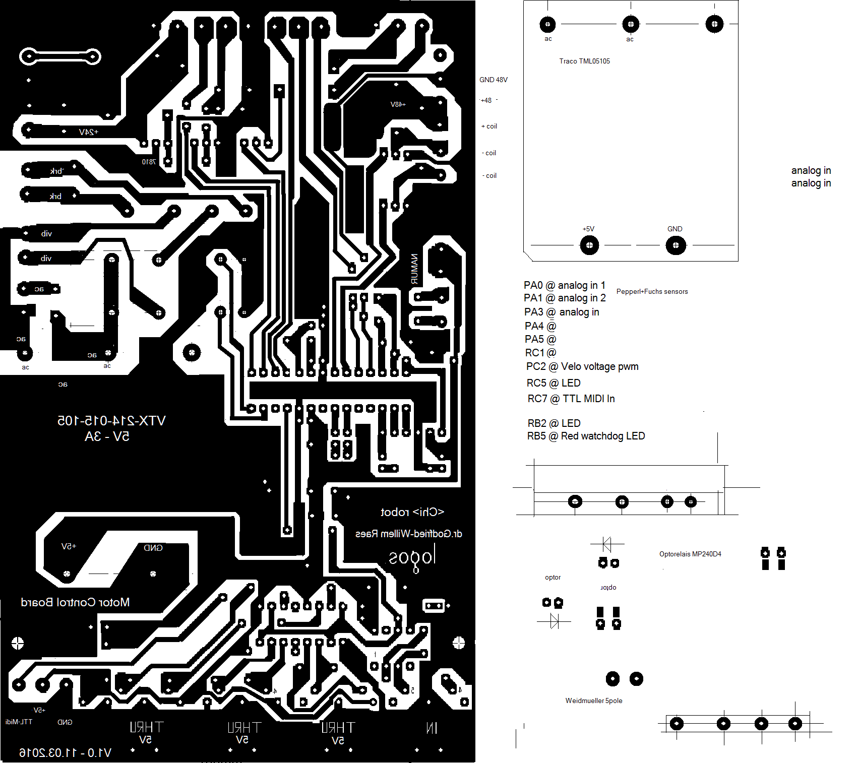
- Motor control and midihub board:
- Firmware for this board: Chi_Mot.bas,
hex dump of the firmware: Chi_Mot.hex
- PCB for this board.
- Light bulbs:
- 24 V, controlled by the motor board (dimmable, tungsten light bulbs,
note 122)
- 24 V, red LED strips controlled by the demodulator board (notes 120,
121)
