|
Microtonal Musical Robot |
|
<Bug>
a robotic and moving Bb flugelhorn dr.Godfried-Willem RAES 2016-2020 |
|
Microtonal Musical Robot |
|
<Bug>
a robotic and moving Bb flugelhorn dr.Godfried-Willem RAES 2016-2020 |
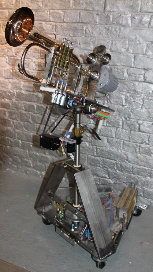
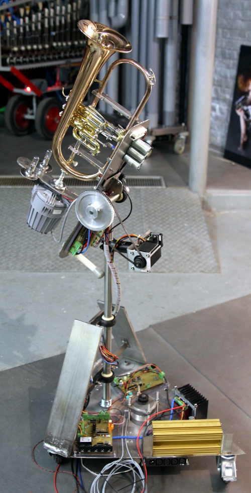
Robot: <Bug>
When starting the design and construction of this musical robot, we could build
further on the experiences gained through the realization of five automated
brass instruments build since 1999: <So>, a sousaphone, <Korn>,
a cornet, <Heli>, a helicon, <Bono>, a valve trombone and <Horny>,
a French horn. This new robot, an automated flugelhorn, was designed and constructed
to the order of LOD, for a theater production 'Helden' with Josse De Pauw. Musically
speaking the cornet, the trumpet and the flugelhorn are very similar instruments,
differing only in the timbre they produce. The flugelhorn is said to sound more
mellow than the trumpet, the cornet finding a place in between. The ambitus,
for Bb instruments, is the same. The name given to this robot was derived from
the Dutch naming of this instrument 'bugel', although the word bugle is also
common in English, referring to a valveless instrument however. The term valve
bugle is often used in English and refers to exactly the same instrument, the
flugelhorn. Organologically speaking it's a saxhorn, its invention going back
to the first half of the 19th century. The bore is much more conical as compared
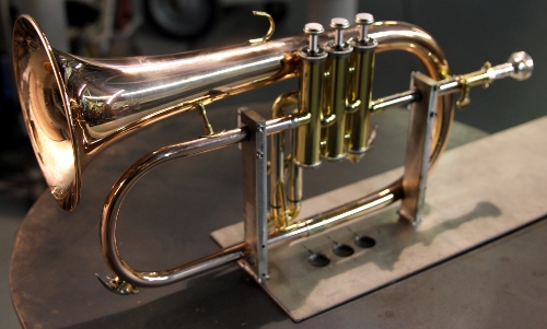
to the trumpet. Here is a picture of the instrument: 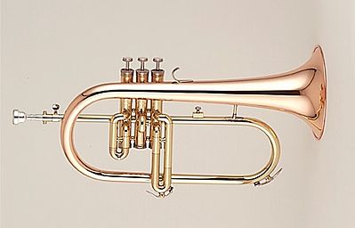
Thus it made sense to start the design of this robot by examining the <Korn> robot and improving over it where ever possible. Main improvements we envisaged were the sound volume, the attack characteristics and the speed of response. For the <Bug> design, we did not start with a mechanical design for an artificial embouchure with mouth, lips and mouthpiece coupled to and in acoustic interaction with the tubing of the instrument, as we did in <So> and the first version of <Bono>, but rather used a membrane compressor directly coupled to the flugelhorn via a capillary comprised in the original mouthpiece.The motor driver causes resonance in the flugelhorn tubing, but in this case there is no unidirectional windflow through the instrument. When a note is requested from the bugle, the firmware will calculate the optimum valve combination -including non orthodox fingerings- for the requested pitch. Thus a resonant standing wave in the instrument can be produced. Microtonal pitches are implemented such that the instrument is capable of performing quartertone music, as well as a wide range of different tunings and temperaments with great perfection. The relatively low Q-factor of the horn (compared to strings...) as an acoustic resonator renders this very well possible. The signal generated in the motor was shaped after a physical model of the air pressure waveform in the mouth cavity of a player. (Beauchamp, 1975,1980). Since there is no loop coupling from the resonator to the generator, the sound generation mechanism is a hybrid somewhere between synthetic/electronic and natural/acoustic. The advantage being that the reliability of the robot becomes very high, but this is obtained a bit at the detriment of realism, in particular with regard to the onset of the sounds, A dynamic formant filter was added using an electronic circuitry, in this case a pair of germanium diodes in series with a resonant LC circuit Thus the sound color will be to a certain extend a nonlinear function of loudness, conform to acoustic reality.
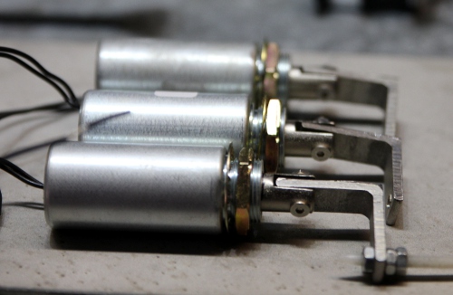
The valves are used in this instrument to tune the fundamental frequency of
the instrument. The valves can be controlled independently from the mouth driver
frequency. They are mechanically driven by unipolar pull solenoids (Emessem
types) and use the return spring provided in the pistons. The notes that are
normally produced using different valve combination, following theory are: 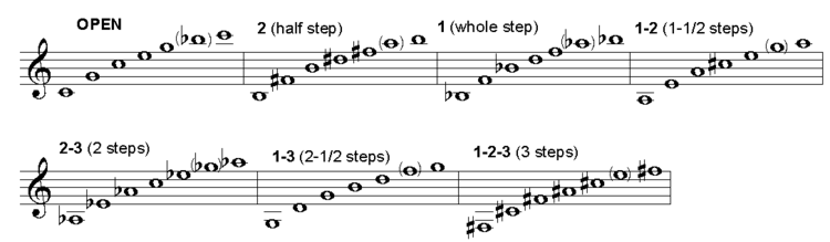 Note that this is untransposed, so in reality everything will sound a full tone
lower on a Bb instrument. However, we found out that using the valve combinations
entailed by this system, does not lead to optimum resonance in the instrument.
Thus we used the optimal valve combinations based on empirical acoustic measurement.
A deficiency we encountered in our <Korn> robot was that the buildup of
a sound pressure wave in the instrument was anticipating the valve movement.
The valves take about 10 ms to take position, thus here we delayed the driver
signal with the same amount in all cases where changes of fingering are involved.
This introduces some latency but makes the sound quite a bit more realistic,
in particular for the attack portion of the envelope.
Note that this is untransposed, so in reality everything will sound a full tone
lower on a Bb instrument. However, we found out that using the valve combinations
entailed by this system, does not lead to optimum resonance in the instrument.
Thus we used the optimal valve combinations based on empirical acoustic measurement.
A deficiency we encountered in our <Korn> robot was that the buildup of
a sound pressure wave in the instrument was anticipating the valve movement.
The valves take about 10 ms to take position, thus here we delayed the driver
signal with the same amount in all cases where changes of fingering are involved.
This introduces some latency but makes the sound quite a bit more realistic,
in particular for the attack portion of the envelope.
High brass instruments in their normal human and musical biotopes tend to move quite a bit in space. The highly directional characteristic of these instruments make this also an expressive valuable parameter. Thus we tried to implement movement in two degrees of freedom in this robot: the flugelhorn can be tilted in the vertical plane over an angle of about 90 degrees and in the horizontal plane, it can rotate over nearly 320 degrees. This conforms pretty well to what human players do in terms of movement on stage. The movements cannot be very fast however, at least not much faster than what a real flugelhorn player could do whilst playing. Horizontal movement is faster than the vertical movement, the forces involved in horizontal movement being much smaller than in the case of vertical movement. However, the intention never was to render Doppler effects possible... Note that on a cold boot, the robot will always perform a calibration of its movement. During this calibration phase the red light on the hub board (the board with the MIDI connectors) will be on and the robot will not be listening to any midi commands sent to it. Before switching the power on, make sure the robot is in a more or less central position, both vertically (pointing straight forward) and central horizontally. As long as power is switched off, the positions can be adjusted manually. Never ever do this when the power in switched on, as this will confuse the firmware and cause forcing on the motors excerting braking force against movement.
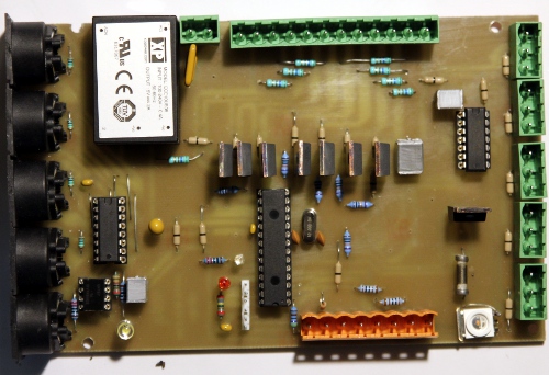
The electronic circuitry -in overview- consists of four PC-boards:
Overview: 
1. Midi-hub board: This board, using a Microchip 18F2525 controller, takes care of the Midi I/O handling and communication as well as the control of all movements: horizontal stepping motor with two end sensors (Pepperl+Fuchs) , and vertical stepper motor with tilt sensor (Penny & Giles). Circuit details, including the PCB design, can be found at the very end of this webpage.
2. Vertical stepping motor driver board using a Nanotec SMC42 compact microstep
constant current driver. 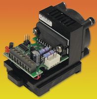 The
noisy fan was removed as well as the DIN-rail mount. The motor is a Nanotec
ST5709L-1108-B. The operating current is set to 2 A.
The
noisy fan was removed as well as the DIN-rail mount. The motor is a Nanotec
ST5709L-1108-B. The operating current is set to 2 A.
 This
motor is designed for 200 steps for a complete rotation in full step mode. In
this robot, the motor is driven in microstepping mode at 8 clocks for a single
step. For the vertical position control we used a Penny+Giles analog tilt sensor
connected to the an0 analog input of the PIC microprocessor.
This
motor is designed for 200 steps for a complete rotation in full step mode. In
this robot, the motor is driven in microstepping mode at 8 clocks for a single
step. For the vertical position control we used a Penny+Giles analog tilt sensor
connected to the an0 analog input of the PIC microprocessor.
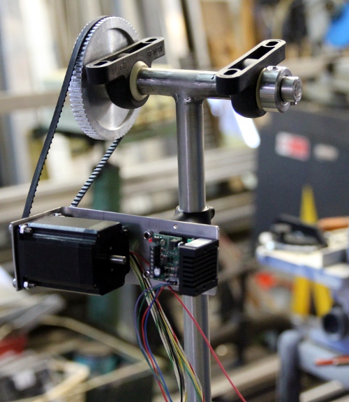
3. Horizontal movement motor: MAE HY200 type  .
The motor controller here is a Geckodrive G203V.
.
The motor controller here is a Geckodrive G203V.
3. Pulse & Hold board: This board steers the three solenoids for the pistons.
The light bulbs and LED's mapped on the midi notes 120 to 127 are also controlled
by this microprocessor board. The board is mounted on the upper part, below
the membrane compressor. The circuit for the pulse/hold circuit applied for
the valves is: 
4. Sound generator board: This board steers the 75 Watt motor compressor horn driver via an audio amplifier module. A 16-bit processor is used to generate the required waveform and two analog multipliers are used for envelope shaping and amplitude modulation. Thus we could maintain audio resolution even at the lowest soundlevels. Handling this in the full digital domain would have required a 32-bit processor. The analog dynamic formant filter also found a place on this board.
All these components are on the upperside of the bottom plate.
Power supply voltages and currents:
Midi Mapping and implementation:
Midi channel: 12 (fixed in the firmware)
Midi note range: 52 to 94. (Optimum sound in the range 66-89) Note on, velocity
is implemented and steers the level of the sustain phase in the adsr.
Note Off commands are required, but can be dropped for pure legato playing. Note off with release is implemented and can steer the release phase of the envelope. Note Off commands for notes that were not sounding are disregarded.
Controllers:
Controller 1: Noisiness of the sound [default = 20]
Controller 3: FM modulation depth (vibrato depth). Large values can cause audible artifacts, due to the modulation of the sampling frequency.
Controller 4: FM modulation speed. (vibrato speed)
Controller 5: AM modulation depth (tremolo depth)
Controller 6: AM modulation speed (tremolo speed)
Controller 7: used as a general volume controller. Note that timbre will change
as the volume is changed. On high settings, the formant frequency becomes more
dominant. [default = 100]
Controller 10: (Panning) Horizontal movement controller. Value 64: center, 127->0= move left (CCW), 0->127=move right(CW). The firmware will recalibrate on each of the extreme positions (0 or 127). The full semicircle takes about 1 second in time., depending of course on the setting for controller #31 (motor speed). The firmware assumes that after a cold start, the flugelhorn is in a more or less central position. It will recalibrate whenever an end position is encountered.
Controller 11: Tilt or inclination controller. Value 64 = Horizontal, values < 64 = downwards, >64 upwards. After reset and on cold boot, it will default to 64.
Controller 13: allows changes of valve fingering during sounding notes. Bit 0 corresponds to the 1/2 tone valve, bit 1 to the 1 tone valves, and bit 2 to the 3 semitone valve. Using this controller it is also possible to change the fingering for a sounding note whilst it is sounding, thus rendering some sound coloration possible without changing the actual pitch.
The table below gives all details:
Ctrl 13 Value -1/2t (valve 2) -1t (valve 1) -1 1/2t (valve 3) 0 off off off 1 on off off 2 off on off 3 on on off 4 off off on 5 on off on 6 off on on 7 on on on
Controller 15: ADSR-period [default 40]
Controller 16: used to control the duration of the attack phase in the ADSR
cycle. [default 16]
Controller 17: set the level of the attack of the sound defined as the extra
boost above the sustain level set with the velo byte.[default 127]
Controller 18 is used to control the duration of the decay after the attack,
the time required to reach the sustain level of the sound. [default 18]
Controller 19 steers the duration of the release decay (from sustain level to
zero) starting after reception of a note off command. Release will we canceled
or interrupted with a new note on command if such a command comes within this
time. [default 64]
The interdependencies of these controllers together with the velo byte is shown in the graph below:
Controller 20: Tuning. To be implemented.
Controller 20 - tuning for the flugelhorn. By default equal temperament and
A = 440 Hz for value 64. Acceptable values for this controller are limited to:
Controller 25: valve movement force controller. With value 18, the movement
is smooth and a bit sluggish, whereas with 127 it may get noisy but very fast.
With values below 18, valve movement may become a bit unpredictable since the
movement will depend on wear, temperature, return spring force variations and
greasing of the pistons. After a cold start, this controller will be in a default
64 position.
Controller 26: This controller steers the time the valves stay in their position after reception of a note-off command. This implements some resonance in the instrument after the excitation from the mouthpiece has stopped. It also avoids unnecessary mechanical noise from the valves, in particular on repeated notes or notes that can be produced with the same valve combination.
Controller 31: Motor speed for the horizontal motor (left-right movements). The speed can be varied between a fixed minimum value and a (safe) and fixed maximum value. Value 0 sets the horizontal motor to move at the slowest speed.[default 80]
Controller 32: Horizontal motor acceleration/deceleration time. On cold boot this controller is always set to 100. Larger values lead to a longer acceleration time on horizontal motor movement starts as well as to longer slowdown times at approaching the destination. Acceleration and deceleration are always symmetric. As a consequence, small movements will be performed slower than longer trajects. The larger the value for this controller, the smoother the movements will be performed.
Controller 33: Vertical motor speed. (Up-down movement). At high speed settings, oscillations can occur.
Controller 66: Power on/off switch (0 = off, any other value is on). Power off also resets all controllers to their default startup values. Also resets the program change to the default startup setting.
Controller 69: Enable or disable automation of the left and right eye lights on the bugle. Default value : > 0, ON. To switch this off, send controller 69 with value = 0.
Controller 80: Dynamic range mapping. The default is 64, resulting in a 40dB dynamic range.
| value | mapping |
| 0-30 | 20dB |
| 31-62 | 30dB |
| 63-94 | 40dB |
| 95-126 | 50dB |
| 127 | 60dB |
Controllers 100, 101, 102, 103: parameters for waveshape. Program change must
have been set to Parametric1 in order for this to work. It is mandatory that
Ctrl100 < Ctrl101 < Ctrl102 < Ctrl103. After reception of controller
103, the wave table will be recalculated. Following graph describes the waveform
and its parameters: 
Controller 104: parameter for setting the symmetry when Program Change has been set to Smoothsquare prior to setting the controller value. Value 64 makes a symmetric square. Valid values are between 1 and 126.
Controllers 105 and 106: parameters for the minimum and maximum points of a
triangle wave. Program Change must have been set to sawtooth prior to sending
these controller values. The parameters will be clear from following waveform
graph:  The wave tables
will be recalculated after reception of the second parameter.
The wave tables
will be recalculated after reception of the second parameter.
Controller 107: parameter for the pulsewidth: range 2 - 126. The graph illustrates the parameter:
Controller 108: parameter for setting the symmetry when Program Change has been set to Assin prior to setting the controller value. Value 64 makes a symmetric sinewave. Valid values are between 1 and 126. The graph illustrates the parameter:
Controller 109: parameter for setting the symmetry when program change has been set to DirtAssin prior to setting the values of the two controllers.
Controller 110: parameter to set the level of noisiness in the waveform. The wave table for the DirtAssin program will only be recalculated after reception of this controller.
Controller 123: switches the sounding note off, unpowers the steppers, dims all the lights.
Program change: implemented to change the wavetable in use for the sound excitation. Following waves are implemented, using the lowest 4 bits of the value.:
Values > 15 (using the 3 highest bits) are used to change the lookup tables in use for the valve combinations. So far following programs are implemented:
Program change commands take some time as the microcontroller recalculates them on the fly. Therefore they should not be issued whilst the robot is playing notes as audible glitches in the sound may occur.
Lights: The lights are mapped on very high midi-notes as follows:
Pitch bend: The <Bug> robot can be used in any tuning system. In the drawing below we give the coding example for a quartertone scale:
 Most good sequencer
software (such as Cakewalk or Sonar) uses the signed 14 bit format. Note that
one unit of the msb corresponds exactly to a 0.78 cent interval. To convert
fractional midi to the msb only pitchbend to apply follow following procedure:
if the fractional part is <= 0.5 then msb= 63 + (FRAC(note) * 128), if the
fractional part is larger than 0.5, we should switch on the note + 1 and lower
the pitch with msb= (1-FRAC(note)) * 128. Note off does
reset the pitch bend for the playing note! The resolution implemented on <Bug>
for pitch bend (and vibrato) is limited to 1/10th of a semitone.
Most good sequencer
software (such as Cakewalk or Sonar) uses the signed 14 bit format. Note that
one unit of the msb corresponds exactly to a 0.78 cent interval. To convert
fractional midi to the msb only pitchbend to apply follow following procedure:
if the fractional part is <= 0.5 then msb= 63 + (FRAC(note) * 128), if the
fractional part is larger than 0.5, we should switch on the note + 1 and lower
the pitch with msb= (1-FRAC(note)) * 128. Note off does
reset the pitch bend for the playing note! The resolution implemented on <Bug>
for pitch bend (and vibrato) is limited to 1/10th of a semitone.
Technical specifications:
Design, research and construction: dr.Godfried-Willem Raes (2016-2020)
Collaborators on the construction of this robot:
Music composed for <Bug>:
| Back to Main Logos page:index.html | To Godfried-Willem Raes personal homepage... | To Instrument catalogue |  |
Construction & Research Diary:
 .
. Both vertical and
horizontal movement will be implemented: up-down and left-right.
Both vertical and
horizontal movement will be implemented: up-down and left-right.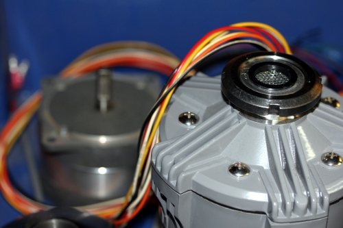 A
stepping motor and a membrane compressor driver. The flugelhorn -brand new,
600 Euro- came in... the first design problems rise up: the line through the
valves crosses the main instrument pipe on the low side valves, so in-line
activation of the valves from underneath requires some redesign and cannot
be optimal. Friction will be unavoidable.
A
stepping motor and a membrane compressor driver. The flugelhorn -brand new,
600 Euro- came in... the first design problems rise up: the line through the
valves crosses the main instrument pipe on the low side valves, so in-line
activation of the valves from underneath requires some redesign and cannot
be optimal. Friction will be unavoidable.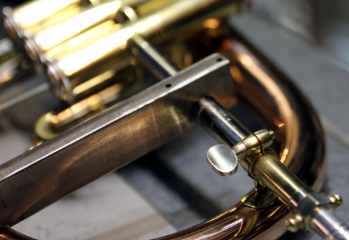
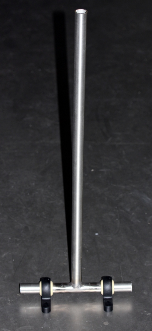
 Test mount of the tractures after welding the vertical posts:
 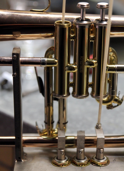 We will use M4 threaded rods made from nylon, to dampen solenoid and mechanical
noise. Start construction of the holder for the membrane compressor. This
has to be minimum 5 mm thick stainless steel (50 x 5). Should lights be implemented?
Two blue eyes would be kind of nice... Mouthpiece to fit the compression driver
turned on the lathe. Precision work this is. Six working days far we are with
it...
We will use M4 threaded rods made from nylon, to dampen solenoid and mechanical
noise. Start construction of the holder for the membrane compressor. This
has to be minimum 5 mm thick stainless steel (50 x 5). Should lights be implemented?
Two blue eyes would be kind of nice... Mouthpiece to fit the compression driver
turned on the lathe. Precision work this is. Six working days far we are with
it... 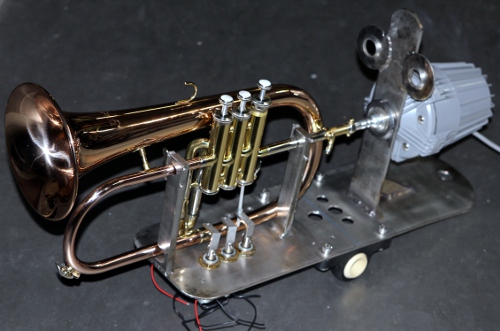 For mounting the special nut on the compression driver, a special tool, a
hook wrench, is required:
For mounting the special nut on the compression driver, a special tool, a
hook wrench, is required: 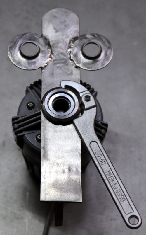 This is a detail of the worked mounthpiece and the fit to the driver:
 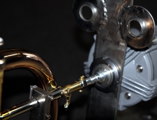 .
Tubular lites (tungsten filament) mounted on the bottom plate of the horn
assembly. On the underside, we mounted a red LED strip light. All lites operate
on the 24V power supply. Balancing point for the assembled structure determined
and two nylon bearings for 15 mm tubing mounted on the determined exact spot.
Mounting with four M8 x 25 cylinder bolts.
.
Tubular lites (tungsten filament) mounted on the bottom plate of the horn
assembly. On the underside, we mounted a red LED strip light. All lites operate
on the 24V power supply. Balancing point for the assembled structure determined
and two nylon bearings for 15 mm tubing mounted on the determined exact spot.
Mounting with four M8 x 25 cylinder bolts.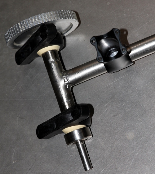
 All
sizes in mm. The distance from the motor axle to the rotating rod is to be
determined, as it will depend on the dented belt to be used. Start sawing
of the required pieces under the correct angles from stainless steel 30 x
10 and 100 x 10. Suitable wheels with brakes bought: building height 100 mm.
All
sizes in mm. The distance from the motor axle to the rotating rod is to be
determined, as it will depend on the dented belt to be used. Start sawing
of the required pieces under the correct angles from stainless steel 30 x
10 and 100 x 10. Suitable wheels with brakes bought: building height 100 mm.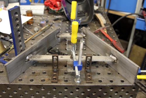 Here is the finished assembly for the horizontal movement:
  Base
plate sawn and sizing determined. Decided to mount it on three wheels, not
four. Tentative placement of components.
Base
plate sawn and sizing determined. Decided to mount it on three wheels, not
four. Tentative placement of components.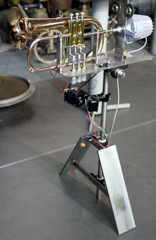 It is clear that the vertical movement will have to be assymetric. The trajectory
for downwards will be much smaller than for upwards movement.
It is clear that the vertical movement will have to be assymetric. The trajectory
for downwards will be much smaller than for upwards movement. 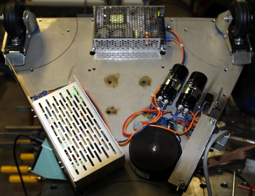
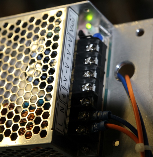
 SMPS voltages checked and found o.k.
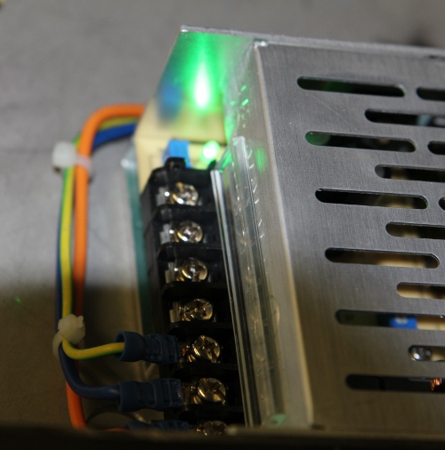
 Vertical
stop designed using a nylon M20 bolt with two nuts. This is how far we are
today:
Vertical
stop designed using a nylon M20 bolt with two nuts. This is how far we are
today:  Considering
to swap front and backside on the design...
Considering
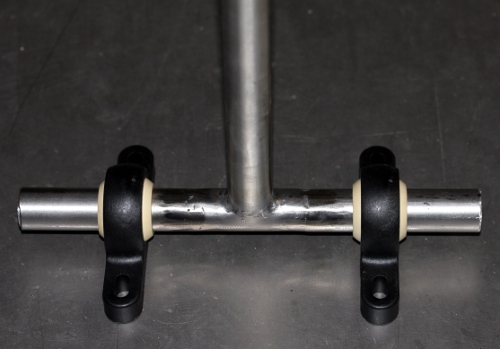
to swap front and backside on the design... To
make this possible we TIG welded a T-piece in 2 mm stainless steel. Wiring
of the valves and the lights finished, using 2-pole Weidmueller connnectors
to the pulse/hold board.
To
make this possible we TIG welded a T-piece in 2 mm stainless steel. Wiring
of the valves and the lights finished, using 2-pole Weidmueller connnectors
to the pulse/hold board. 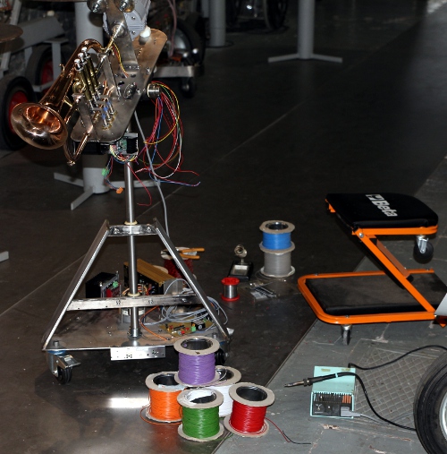
 Filter component values still have to be calculated. Implemented in the firmware
so far: pitch generator, ADSR control, Pitch bend, global volume control.
Still to be done: noisyness or frequency-jitter, lookup tables for tunings,
vibrato (FM) and tremolo (AM). These need separate timers. This is going to
be a very nice model for a monophonic synth based on acoustical modelling.
The use of analog circuitry (multipliers) for all amplitude related parameters
is a great benefit for the sound quality. If we would have implemented it
digitally, on a 16-bit processor, this would go at the detriment of resolution
and unwanted noise/artifacts.
Filter component values still have to be calculated. Implemented in the firmware
so far: pitch generator, ADSR control, Pitch bend, global volume control.
Still to be done: noisyness or frequency-jitter, lookup tables for tunings,
vibrato (FM) and tremolo (AM). These need separate timers. This is going to
be a very nice model for a monophonic synth based on acoustical modelling.
The use of analog circuitry (multipliers) for all amplitude related parameters
is a great benefit for the sound quality. If we would have implemented it
digitally, on a 16-bit processor, this would go at the detriment of resolution
and unwanted noise/artifacts. 
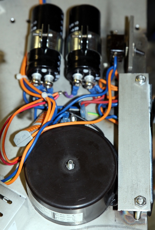
 The component topology is:
  Firmware
rewritten with a better implementation for the ADSR. Function of the velocity
byte redefined. The use of a variable sampling rate at 256 times the required
audio frequency with the PWM frequency set to 1.8MHz seems to work quite well.
Pitch bend implementation, tentative, added to firmware. Left to be done here:
basic tuning, vibrato and tremolo. This is the soldered board:
Firmware
rewritten with a better implementation for the ADSR. Function of the velocity
byte redefined. The use of a variable sampling rate at 256 times the required
audio frequency with the PWM frequency set to 1.8MHz seems to work quite well.
Pitch bend implementation, tentative, added to firmware. Left to be done here:
basic tuning, vibrato and tremolo. This is the soldered board: 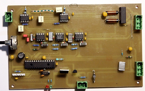

 Almost done. The only thing left to be done now is the wiring to the power
supplies on the underside of the robot and the sensors for the horizontal
movement. This we can only do if the ordered dented wheel flows in from MEA.
Chances are <Bug> can undergo its first tests tomorrow...
Almost done. The only thing left to be done now is the wiring to the power
supplies on the underside of the robot and the sensors for the horizontal
movement. This we can only do if the ordered dented wheel flows in from MEA.
Chances are <Bug> can undergo its first tests tomorrow...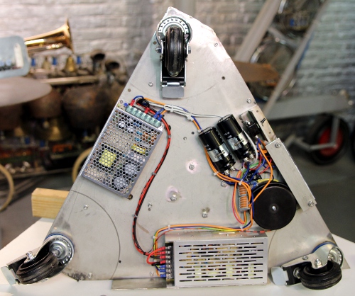 On firing it all up... nothing happening. Power supplies remain dead. Apparently
we miswired the 48V supply, thus blowing up the 24V supply... The 48V supply
survived the shock. The 24V supply appears unrepairable. Replacement part
(XP Power LCL150PS24) ordered. After fixing some minor wiring bugs on the
amplifier, we got this part working. The tuning is about a quarter tone off
however. This can be fixed in the firmware. The sound quality in the low register
is quite good. Needs more sharpness in the trebble though. The valve board
appeared to have a short on the +24V line. Short found and removed. Now waiting
for a new power supply.
On firing it all up... nothing happening. Power supplies remain dead. Apparently
we miswired the 48V supply, thus blowing up the 24V supply... The 48V supply
survived the shock. The 24V supply appears unrepairable. Replacement part
(XP Power LCL150PS24) ordered. After fixing some minor wiring bugs on the
amplifier, we got this part working. The tuning is about a quarter tone off
however. This can be fixed in the firmware. The sound quality in the low register
is quite good. Needs more sharpness in the trebble though. The valve board
appeared to have a short on the +24V line. Short found and removed. Now waiting
for a new power supply. 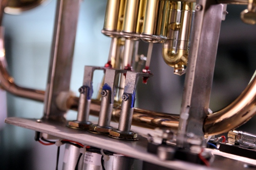 Work on the horizontal and vertical movement mechanics. Vertical movement
dented wheel extended with a mover to transmit movement to the flugelhorn
mounting plate. This piece mounts on the wheel with a single M6 x 16 bolt.
Vertical movement now works fine, but the motor is not powerfull enough to
perform the full mechanical traject that would be possible. Horizontal motor
still not operational. We still have to mount the sensors and make up our
mind as to frontside or backside...
Work on the horizontal and vertical movement mechanics. Vertical movement
dented wheel extended with a mover to transmit movement to the flugelhorn
mounting plate. This piece mounts on the wheel with a single M6 x 16 bolt.
Vertical movement now works fine, but the motor is not powerfull enough to
perform the full mechanical traject that would be possible. Horizontal motor
still not operational. We still have to mount the sensors and make up our
mind as to frontside or backside...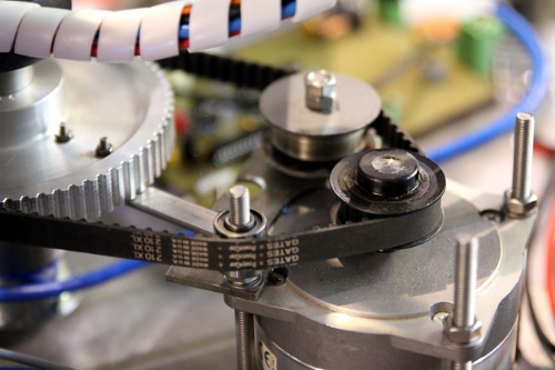 Column
shortened with some 140 mm, so the total height of the robot (with the flugelhorn
in a horizontal position) becomes 1070 mm.
Column
shortened with some 140 mm, so the total height of the robot (with the flugelhorn
in a horizontal position) becomes 1070 mm.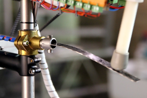 The up down traject can now be enlarged a bit. Definitive allignment of the
valve mechanism and the tractures. M4 bolts secured with red Loctite lacquer.
Considering to make a protective cap over the circuitry, taking into account
the envisaged use of the robot.
The up down traject can now be enlarged a bit. Definitive allignment of the
valve mechanism and the tractures. M4 bolts secured with red Loctite lacquer.
Considering to make a protective cap over the circuitry, taking into account
the envisaged use of the robot.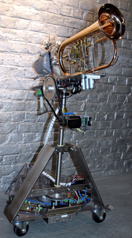
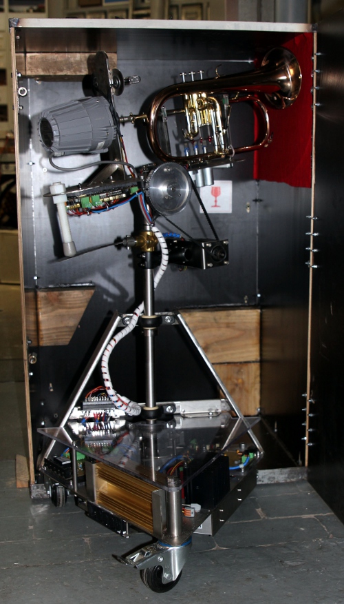
 First
photoshoot with <Bug>
First
photoshoot with <Bug>
To do:
| (Terug) naar logos-projekten: | Terug naar Logos' index-pagina: | Naar Godfried-Willem Raes personal homepage... | Naar katalogus instrumenten | |
Last update: 2023-10-07 by Godfried-Willem Raes
The following information is not intended for the general public, but is essential for maintenance and servicing of the robot.
Technical drawings, specs and data sheets:
Proximity sensors: Pepperl+Fuchs, NBN4-12GM40-Z0 (Horizontal movement sensors)
Tilt sensor: Penny+Giles STT280/60/P2 (Datasheet: STT 280/60/P2. ) (Vertical movement sensor)
Horizontal motor controller (G103V)
Horizontal stepping motor: MAE HY200 3424 170 ( 1,7A - 2 Ohm with windings in series, 2.38A - 1 Ohm, with windings in parallel) or MAE HY200 3424 470 ( 4.7A - 1 Ohm with windings in series). Maximum voltage on these motors is 90 V.
Vertical stepping motor: Nanotech (SMC42)
Valve lookup tables (according to acoustic theory)
Power supply:
The power supply for the power amp determines maximum power. With the values shown, we have a maximum output voltage from the power amp of 17 Vrms. Our load -the membrane compressor- has 16 Ohm impedance and thus maximum deliverable power will be 17 W rms.
The 24V/150W power supply is an enclosed unit made by XP-Power, part nr. LCL 150PS24 with medical specifications. Farnell order nr.:1738313. Datasheet.
Wiring & circuit details midihub and motor-control board:
Circuit drawing:
PCB design for this circuit:
PCB: 
Soldered board:
Firmware for the hub board:
Pulse-hold board for the valves and the lights:
PCB: 
Populated board: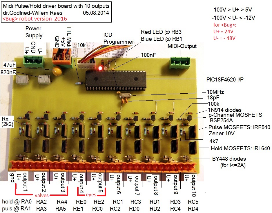
Firmware for this board: Bug_Valves.bas Hex dump for this board: Bug_Valves.hex
Compressor driver board (monophonic synth with acoustical modelling)::
Circuit drawing:
PCB for this circuit:
Soldered board: (Formant
filter not yet mounted on this picture).
Firmware for this board: PIC24_Bug.bas (source code for Proton24 compiler) and hex dump: PIC24_Bug.hex
Wiring of the connector between moving upper part and lower part:
Flugelhorn: Selmer 'Vincent Bach' horn.
Mouthpiece: Bach Flugelhorn 3427C, adapted on the lathe to fit the membrane compressor.
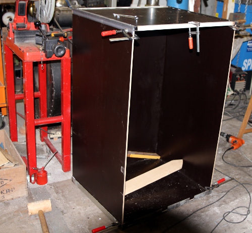
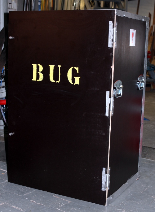
The <Bug> robot has a special flightcase. Following pictures are made to clarify the way <Bug> should be placed in its flightcase:

References:
Beauchamp, J.W. "Analysis and Synthesis of Cornet Tones Using Nonlinear Interharmonic Relationships". In: j-aes, volume 23, number 10, pages 778--795, 1975.
Beauchamp, J.W., "Analysis of Simultaneous Mouthpiece and Output Waveforms of Wind Instruments" . In: j-aes, 1980, Preprint No. 1626,
Benade, Arthur .H., "Fundamentals of Musical Acoustics". Ed.: Oxford University Press, 1976.
Fletcher, N.H. & Tarnopolsky, A. "Blowing pressure power and spectrum in trumpet playing" In: J. Acoust. Soc. Am., volume 105, number 2, part 1, 1999.
Martin, Daniel W., "Lip vibrations in a Cornet Mouthpiece", In: J.Acoust.Soc.Am. vol13 . 1942
National Semiconductor, LM18298 Dual Full-Bridge Driver, datasheet. April 1992
Raes, Godfried-Willem, "Kursus Akoestiek", Ghent University College 1982/2014, Internet: http://www.logosfoundation.org/kursus/4023.html
Raes, Godfried-Willem, "Logos @ 50, het kloppend hart van de avant-gardemuziek in Vlaanderen", ed. Stichting Kunstboek, Oostkamp, 2018
Raes, Godfried-Willem, "Expression control in musical automates", 1977/2021,
Raes, Godfried-Willem, "Trumpeter", 2021
Rose,Nicholas and Holloway, Damien, "Finite element modeling of brass musical instruments', in: Proceedings of Acoustics, Fremantle, Australia 2012.
Smith, Bob H., "An Investigation of the Air Chamber of Horn Type Loudspeakers", in: The Journal of the Acoustical Society of America 25, 305-312 (1953); https://doi.org/10.1121/1.1907038
Cost calculation for <Bug>:
1. Parts and components
| Flugelhorn | Vincent Bach - Selmer - Bb |
600.00
|
| Stainless Steel | 21 kg a 5.00/ kg |
105.00
|
| Solenoids | 3 Emessem 24V (@100% DC) |
126.00
|
| Bulbs BA15 | 2 sockets |
18.00
|
| Bulbs | 2 bulbs 24V |
14.00
|
| Tubular bulbs + holders | 3 Festoon sockets and bulbs 24V |
30.00
|
| LED assembly Red | 24V |
18.00
|
| M3 x 20 cilinder bolts and nuts | 10 |
9.00
|
| M3 x 35 cilinder bolts and nuts | 10 |
10.00
|
| M4 x 20 cilinder bolts and nuts | 10 |
7.00
|
| M4 x 16 hex bolts and nuts | 8 |
6.00
|
| M 4 x 35 hex bolt and nut | 4 |
4.00
|
| M5 x 10 cilinder bolts and nuts | 2 |
1.00
|
| M5 x 25 cilinder bolts and nuts | 8 |
8.00
|
| M4 x 10 hex bolts and nuts | 8 |
5.00
|
| M6 x 45 countersunk bolts and nuts | 10 |
15.00
|
| M6 x 16 hex bolts and nuts | 5 |
4.00
|
| M6 x 25 hex bolts and nuts | 2 |
1.00
|
| M6 x 120 hex both and nut | 1 |
3.00
|
| M8 x 25 cylinder bolts and nuts | 4 |
8.00
|
| M8 x 30 cylinder bolts and nuts | 10 |
10.00
|
| M8 x 40 cylinder bolts and nuts | 10 |
11.00
|
| M12 x 35 cylinder bolts and nuts | 3 |
4.00
|
| M12 High nut | 1 (for mounting backwheel) |
8.00
|
| M12 x 120 hex bolt | 1 |
7.00
|
| M20 nylon rod and 2 nuts | 1 |
23.00
|
| M4 nylon threaded rod | 1 |
22.00
|
| 35 mm nut | 1 (for tightening with a 35-50 mm hook wrench) |
27.00
|
| Nylon bearings 25 mm | 4 |
108.00
|
| ball bearing pot | 1 |
12.00
|
| Stepping motor 240W | MAE horizontal motor HY200 3424 470A8 |
260.00
|
| Membrane Compressor 100W | 1 |
210.00
|
| Amplifier module 100W | 1 (Velleman) |
130.00
|
| Helicoil threads M4 | 6 |
3.00
|
| Polycarbonate | 1 m2, 8 mm thick |
78.00
|
| Helicoil M4x6 thread repair set | 1 |
45.00
|
| Cyanoacrylate glue | 1 (Loctite 401, 3g) |
4.00
|
| Blue Loctite silicon compound | 1 tube |
22.00
|
| Nanotech SMC42-2,0-1 | Motor controller vertical movement |
197.00
|
| Nanotech ST5709L1108-B | Stepping motor vertical movement |
126.00
|
| G203V stepper controller | Horizontal motor controller |
285.00
|
| Capacitors 10000uF/100V | 2 |
126.00
|
| Titanium alloy tubular clamp | holder with adjustment for the vertical motor (tube size 25 mm) |
65.00
|
| 12 mm hardened axle | 250 mm |
4.00
|
| Bronze bearings | 2 (12 x 18 x 25 mm) |
12.00
|
| Penny+Giles STT280/60/P2 | angular sensor, vertical movement |
270.00
|
| Pepperl & Fuchs sensors | 2 NBN4-12GM40-Z0, horizontal movement |
138.00
|
| Dented wheel Alu | 2 Type: 72XL037 |
49.00
|
| Dented wheel steel, flanged | 1 Type 14XL037 - vertical movement |
31.00
|
| Dented wheel steel, flanged | 1 Type 18XL037 - horizontal movement |
30.00
|
| Dented belt vertical movement | Powergrip 250XL037 |
5.00
|
| Dented belt horizontal movement | Powergrip 220Xl037 |
6.00
|
| Power supply 48V - 2.3A | Traco |
129.00
|
| Power supply 24V - 6.4A | medical XP-Power type LCL 150PS24 |
265.00
|
| Power supply 2 x 27V - 50W | Toroidal, bridge rectifier and 2 x 10mF caps |
135.00
|
| PCB Pulse-Hold | 10 HV outputs, 30 Mosfet's, 10 Zener diodes, PIC 18F4620 processor, Weidmueller connectors |
260.00
|
| PCB Hub board | 3 analog in, 8 outputs, midi-in, differential thru, TTL midi out PIC 18F2525, 5V power supply module, Weidmueller connectors |
355.00
|
| PCB Generator board | 16 bit PIC 24EP128MC202, 3 op amps, 2 multipliers, Weidmueller connectors, 1% precision resistors, 4 inductors |
435.00
|
| Setting rings 12 mm | 1, stainless steel |
4.00
|
| Setting rings 25 mm | 3, stainless steel |
24.00
|
| Wheels with brakes | 4 ZWR/ZW`EPO/GAT 12/80GL |
96.00
|
| IEC Mains power entry | Schaffner FN-372 6 (230V - 6A) |
7.00
|
| Toggle switch power on/off | 230V / 3A |
5.00
|
| Heatsink 100 x 80 | heatsink for the horizontal motor controller |
32.00
|
| Parabond High Tack 800 | mounting compound |
9.00
|
| Faston connectors, blue | 35, power supply wiring |
11.00
|
| Wire | 25 m, 0.75mm2, 1.5mm2 |
6.00
|
| Tie straps, nylon | 30 |
2.00
|
| Waco connectors, snap in | 2 5-contacts |
3.00
|
| Elco clamps | 2 30 mm |
2.00
|
| Multi-Connector | mating parts (M-F), 30 poles with 6A knife contacts |
38.00
|
| Wiring | 30 m of mounting wire in coded colors |
18.00
|
| Heatshrink tube | Polyolefine 1 m |
6.00
|
| Brass movement blocker | 25 mm clamp with bolts |
14.00
|
| M6 rubber movement stopper | for horizontal movement limiting |
3.00
|
| Loctite red lacquer | for securing valve M4 nuts |
1.00
|
| Felt | for mounting and dampening |
2.00
|
| Blade spring and 1/2" threaded holder | for limiting vertical movement |
5.00
|
| Coated multiplex wood | for flightcase |
76.00
|
| Steel L-profiles | for flightcase 4 kg |
8.00
|
| Handgrips | 4, for flightcase |
20.00
|
| Hinges for flightcase | 3 |
18.00
|
| Loctite fastening | Loctite 243 50ml |
45.00
|
| M6 x 20 bolts and nuts | galvanised, for flightcase |
22.00
|
| Woodscrews | for flightcase |
1.00
|
| Transparent silicon glue | for flightcase |
8.00
|
| Red felt | for flightcase |
2.00
|
| M12 high nuts | 2, for flightcase, stainless steel |
12.00
|
| M12 x 40 | 2, for flightcase, stainless steel, with washers |
7.00
|
| Wood blocks | for flightcase |
2.00
|
| Weatherstrip | 2 mm thick, 3 meter |
3.00
|
| M5 x 16 bolts and nuts | 16 countersunk with 25mm washers, flightcase, handles |
8.00
|
| Foam padding | for flightcase |
5.00
|
| Subtotal: |
5409.00
|
2. Consumables
| Cobalt 3mm drill bits | 10 |
35.00
|
| Cobalt 4mm drill bits | 3 |
12.00
|
| Cobalt 5mm drill bits | 2 |
8.00
|
| Cobalt 8mm drill bits | 1 |
9.00
|
| TIG welding materials | Argon gas and Tungsten electrodes |
50.00
|
| Cutting disks | 12 (A60 T-BF41 125 x 1.0 x 22.2 |
40.00
|
| Sanding disks and paper |
18.00
|
|
| Grinding disk | 1 |
5.00
|
| TIG welding nozzle, nr.5 | 1 |
12.00
|
| Cutting oil | 1 |
1.00
|
| Solder Pb/Sn 40/60 | 5 m |
5.00
|
| Stainless Steel welding electrodes | 10 3.2 mm |
22.00
|
| Aceton | 0.5 l |
4.00
|
| PIC 24 testboard | prototyping board |
127.00
|
| Etching baths | Fe2Cl3 1 liter |
5.00
|
| Methanol | 0.25 l |
2.00
|
| Subtotal: |
355.00
|
3. Depreciations on tools and equipment used (calculated over 2 months)
| Tool | Value | Depreciation percentage / month | |
| Tektronix TDS2024C | 3500 | 2.77% |
194.00
|
| Tektronix Function Generator | 3000 | 2.77% |
166.00
|
| TIG welding equipment | 2000 | 2.77% |
110.00
|
| Contimex Lathe | 2500 | 2.77% |
139.00
|
| Cobalt saw | 2800 | 2.77% |
155.00
|
| Soldering equipment | 1000 | 2.77% |
55.00
|
| Plasma Cutter Genesis | 1200 | 2.77% |
66.00
|
| Proton+ Laptop & ICD | 1800 | 2.77% |
50.00
|
| Lab power supply | 380 | 2.77% |
10.00
|
| Odin column drill | 6000 | 0.92% |
55.00
|
| Welding table | 2500 | 0.92% |
23.00
|
| Subtotal: |
1023.00
|
4. Labor and design (45,-/hour)
| 16.11.2016 | 4 h |
180.00
|
| 17.11.2016 | 8 h |
360.00
|
| 18.11.2016 | 8 h |
360.00
|
| 19.11.2016 | 12 h |
540.00
|
| 20.11.2016 | 7 h |
315.00
|
| 21.11.2016 | 10 h |
450.00
|
| 22.11.2016 | 8 h |
360.00
|
| 23.11.2016 | 10 h |
450.00
|
| 24.11.2016 | 8 h |
360.00
|
| 25.11.2016 | 8 h |
360.00
|
| 26.11.2016 | 6 h |
270.00
|
| 27.11.2016 | 5 h |
225.00
|
| 28.11.2016 | 10 h |
450.00
|
| 29.11.2016 | 10 h |
450.00
|
| 30.11.2016 | 7 h |
315.00
|
| 01.12.2016 | 3 h |
135.00
|
| 03.12.2016 | 9 h |
405.00
|
| 04.12.2016 | 7 h |
315.00
|
| 05.12.2016 | 10 h |
450.00
|
| 06.12.2016 | 8 h |
360.00
|
| 07.12.2016 | 10 h |
450.00
|
| 09.12.2016 | 7 h |
315.00
|
| 10.12.2016 | 9 h |
405.00
|
| 11.12.2016 | 10h |
450.00
|
| 12.12.2016 | 3 h |
135.00
|
| 13.12.2016 | 2 h |
90.00
|
| 14.12.2016 | 5 h |
225.00
|
| 15.12.2016 | 8 h |
360.00
|
| 16.12.2016 | 6 h |
270.00
|
| 17.12.2016 | 8 h |
360.00
|
| 18.12.2016 | 10 h |
450.00
|
| 19.12.2016 | 8 h |
360.00
|
| 20.12.2016 | 7 h |
315.00
|
| 21.12.2016 | 7 h |
315.00
|
| 22.12.2016 | 1 h |
45.00
|
| 23.12.2016 | 3 h |
135.00
|
| 24.12.2016 | 1 h |
45.00
|
| 25.12.2016 | 8 h |
360.00
|
| 26.12.2016 | 6 h |
270.00
|
| 27.12.2016 | 8 h |
360.00
|
| 28.12.2016 | 8 h |
360.00
|
| 29.12.2016 | 7 h |
315.00
|
| 30.12.2016 | 6 h |
270.00
|
| 31.12.2016 | 1 h |
45.00
|
| 01.01.2017 | 2 h |
90.00
|
| 02.01.2017 | 2 h |
90.00
|
| 04.01.2017 | 7 h |
315.00
|
| 05.01.2017 | 5 h |
225.00
|
| 06.01.2017 | 8 h |
360.00
|
| 07.01.2017 | 6 h |
270.00
|
| 08.01.2017 | 5 h |
225.00
|
| 09.01.2017 | 2 h |
90.00
|
| Subtotal: |
15480.00
|
07-09.12.2020: 3 days of work on firmware upgrade.
[EOF]