The Ringmodulator
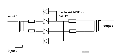
Ring modulators are electronic circuits stemming from early telephony. They are at the essence of the possibility to send and receive many simultaneous telephone conversations through one and the same couple of wires. Soon enough the circuit has found abundant applications throughout 20th century music production and performance. They are fundamental also to the working of radio receivers and emitters, both for AM and FM. The historical passive ring modulator circuit looks like this:
[ref.69.10]
There are two inputs and a single output. The two signals get multiplied in
the germanium diode-ring configuration between the two transformers. Input signals
for this circuit must be kept smaller than 25 mV. That's why there are four
resistors in the circuit. Their value must be calculated such that they are
larger then the conducting resistance of the diodes used under voltage conditions
specified. The diodes must be matched within fractions of a percent. The ideal
transformers for this circuit must be of the toroidal type and extremely well
balanced. Hard to find for audio applications but if you are lucky you can every
so often recycle them from old professional audio equipment stemming from physics
labs, analog computers or electronic music studios. It should be noted, that
the very first circuits, used vacuum tube diodes instead of solid state germanium
of silicon diodes as drawn here. Amongst electronics and music afficionados
on the internet, transformer based circuits as well as designs using vacuum
tubes, still seem to have followers, generally synth players and e-guitarists
with a popular music background. The ringmodulator still seems to have quite
some popularity there. The number of forums we could find is pretty elevated.
Things such as the kind of diodes to be used (germanium, vacuum tube, Shottky,
XOR-circuits) lead to ongoing lengthy discussions. Here are some historical
documents taken from the documentation available at the US patent office: 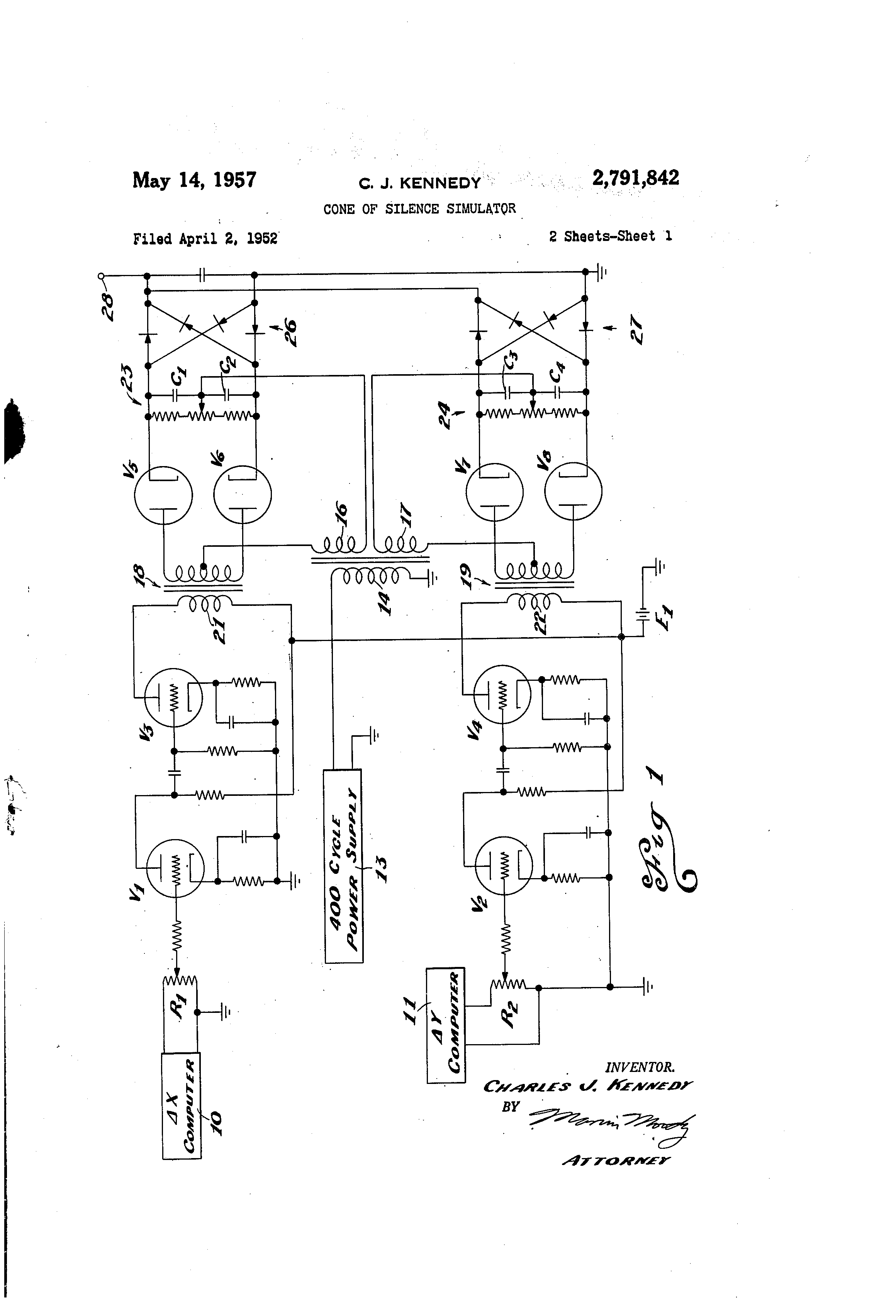
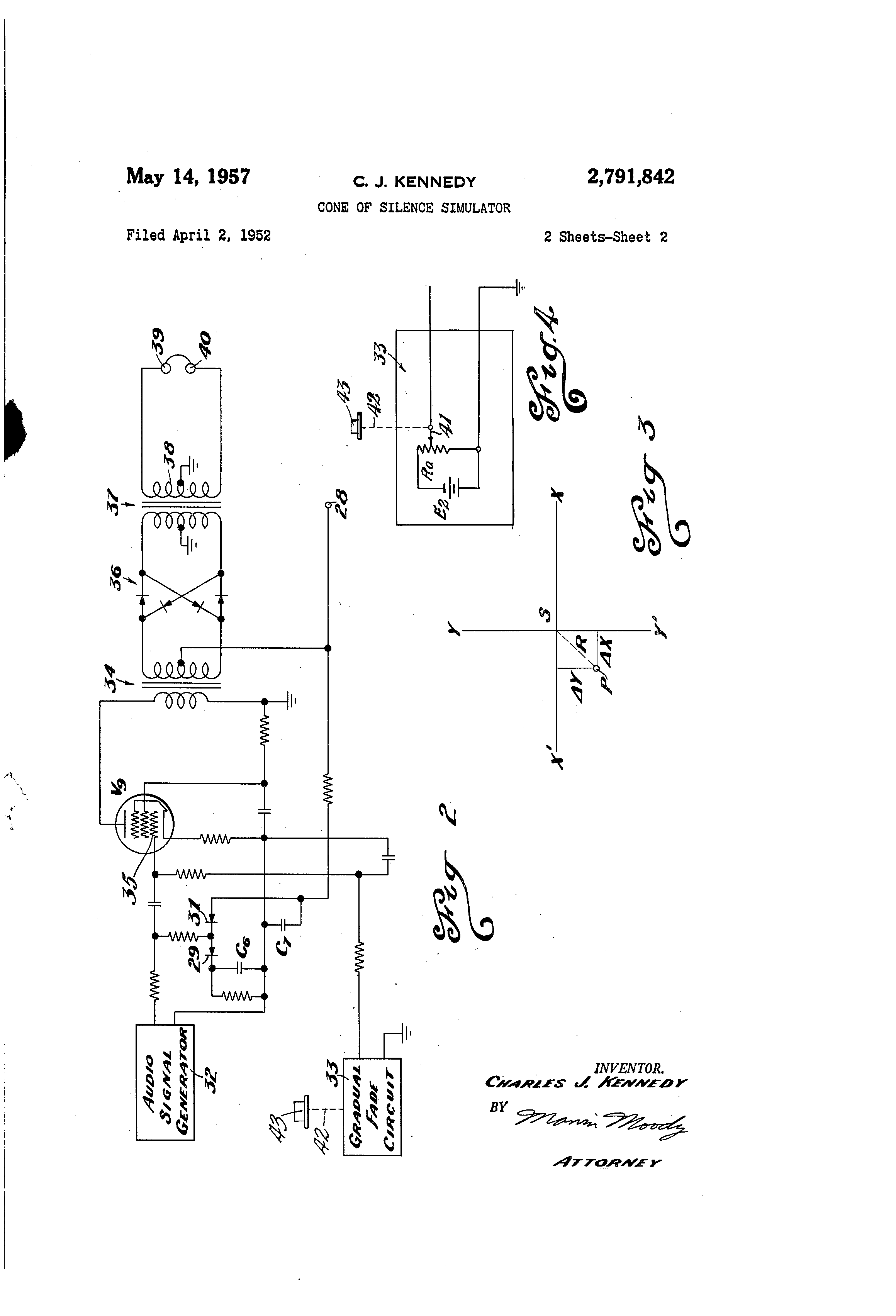 Ringmodulators
of all kinds can readily be found on the market. The Moog model has been quite
popular for a long time:
Ringmodulators
of all kinds can readily be found on the market. The Moog model has been quite
popular for a long time: 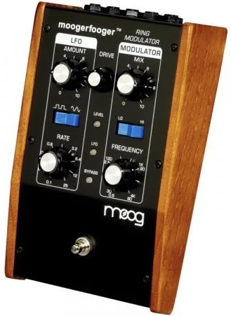 It's
usefullness for the performance of new music scores in general is not evident,
as it is designed with a built-in LFO and carrier frequency generator. The foot-switch
also, reveals the origin of the device as a guitar effect pedal. For most scored
compositions by 'modernist' composers, this model will be not very usefull and
getting or building a ringmodulator will be of much greater help.
It's
usefullness for the performance of new music scores in general is not evident,
as it is designed with a built-in LFO and carrier frequency generator. The foot-switch
also, reveals the origin of the device as a guitar effect pedal. For most scored
compositions by 'modernist' composers, this model will be not very usefull and
getting or building a ringmodulator will be of much greater help.
On a technical level, the classic ringmodulator as shown is a purely analog circuit and its functioning can be analysed as follows.
- Two input signals are required. The output signal contains all sum and difference tones between both input signals, the input signals themselves disappearing from the output signal. From a mathematical point of view, the transfer function seen in the time-domain is:
Uout= (Uin_x * Uin_y) / k
How this connects to the statement about resulting sum and difference tones is a bit more involved. The circuit behaves as a multiplier in the time-domain. Let's suppose the input signals are periodic functions such as:
Uin_x= Upx * COS((wx+ phi_x).t)
Uin_y= Upy * COS((wy+ phi_y).t)
wherein
wx = 2 * Pi * fx
and
wy = 2 * Pi * fy
Thus fx en fy represent the respective frequencies of the input signals and where phi_x, phi_y represent the phase-angles of these signals. Upx and Upy are the peak amplitudes of both signals.
Further development of this product leads to:
Uout = Upx*Upy * {COS[(wx-wy)* t - ph ] + COS[(wx+wy)*t + ph] } * COS(wx+ph* t)
= (Upx*Upy/2) * {COS[wy*t + ph] + COS[-wy* t - ph] + COS[(2*wx +/- wy)* t +/- ph)
(suppose ph = phi_x - phi_y)
Expressed in words, this means that at the output we are getting nothing but the sum and difference tones between the input signals. The transfer function becomes even intuitive of we imagine both input signals being the same. In this case we would get:
Ui = Um * SIN(wx*t) input signal
[Um * SIN(wx*t)] * [ Um * SIN(wx*t)] = (Um * SIN(wx*t))^2
If we now apply a standard rule in goniometry we derive that:
[Um * SIN(wz*t)]^2 = ((Um^2) / 2)) * [1- COS(2*wx*t)]
Or, expressed in words, the output of the circuit offers us a periodic signal with twice the frequency of the input signal. Simply said, we just made an octave doubler. For those amongst our readers wanting to dig further into the internal guts of such modulators and demodulators, we refer to the exhaustive technical literature available on the subject. The printed data books published by Analog Devices and Burr-Brown are invaluable sources of information. A thorough understanding of these devices is essential for a proper understanding of FM-synthesis as it has been fundamental for the development of electronic synthesizers since about 1970. FM-synthesis is entirely based on the multiplication of wave forms.
For pure sine wave input signals, the characteristics of the resulting output signal can be predicted easily, as shown in a few examples:
gives: Uout+=1100Hz (do#)
as well as Uout-= 220Hz (la)
A pure fifth interval thus undergoes a transformation to the interval of an octave plus a natural major third.
U2 = 880 Hz (la')
gives: Uout+=1320Hz (mi)
as well as: Uout-= 440Hz (la)
In this example, the octave between the input signals, gives us an octave and a pure fifth at the output
U2 = 466Hz (sib)
geeft: Uout+= 906Hz (la+)
+ Uout-= 26Hz (la-)
In this case we get at the output
an A raised a quartertone together with a very low A, a quartertone down. The
latter however will be perceived as a fast tremolo. As soon as we try to feed
the ringmodulator with more complex waveforms such as those stemming from acoustic
musical instruments, the results can get very complex. This is caused by the
fact that the multiplier applies its transformation to the entire spectrum found
in the input signals. If we feed at least one of the inputs with spikes or pulses,
we can easily obtain sounds refering to metal percussion instruments such as
gongs and bells. Needless to say that this has fascinated generations of composers
and musicians using technology.
A special application of the ringmodulator is the octave doubler, obtained by
shorting both inputs together and feeding it with a single periodic signal,
as demonstrated earlier mathematically. Also, we can feed one of the inputs
with a wide band noise signal and the other input with a sine wave. At the output
colored noise centered around the frequency of the sine wave will be obtained.
We can also use the ringmodulator as a VCA (voltage controlled amplifier). It
is enough to use one of the inputs as very low frequency input or even feed
it with ADSR signals. As a matter of fact, the VCA is nothing but a specialised
application of the fundamental ringmodulator circuit. Technically a VCA is a
one-quadrant multiplier.
Functionally, we encounter the circuit in many very old as well as new electronic
instruments: the Theremin as well as the
theremin derived Ondes Martenot
If we use the ringmodulator to multiply two signals in the ultrasonic audio range and if their difference tone falls in the audio band, then we can use it to detect just this difference tone as the co-existent sum tone a fortiori will be out of the audio range.
As soon as electronic music studios started rising up in the beginning of the fifties of the 20th century, the ringmodulator became a standard component for the production of electronic music. Early composers that made extensive use of them are Karlheinz Stockhausen (Telemusik, Mantra, Hymnen, Mixtur...), Wladimir Ussachewsky, Gordon Mumma, John Cage, Allan Strange, Alvin Curran... The analog electronic synthesizers as they were build since the seventies, almost all contained at least one patchable ringmodulator (Synket, Putney of VCS3, EMS, Korg, R.Moog, ARP, D.Buchla, Synthelog, Serge etc).
Even in some orchestral compositions one may encounter requests for ringmodulators, for instance the Flemish composer Luc Brewaeys uses them in 'Trajet' and 'Due Cose'. The ringmodulator circuits for these performances were designed and made by us, together with some software to generate the signals to be used as modulators for the orchestra sounds on the inputs. At the time these pieces were written, it was already no longer common usage to use spare sinewave generators to this purpose. MIDI-controlled modular synths could perfectly replace the sinewave generators. Nowadays, the entire setup can be replaced with a simple computer program, a 'patch'.
Some pieces where the score calls for ringmodulators:
Toshi Ichianagi, 'Appearance', for 3 instruments, 2 oscillators and 2 ringmodulators.
Published in Source magazine, issue nr.2,
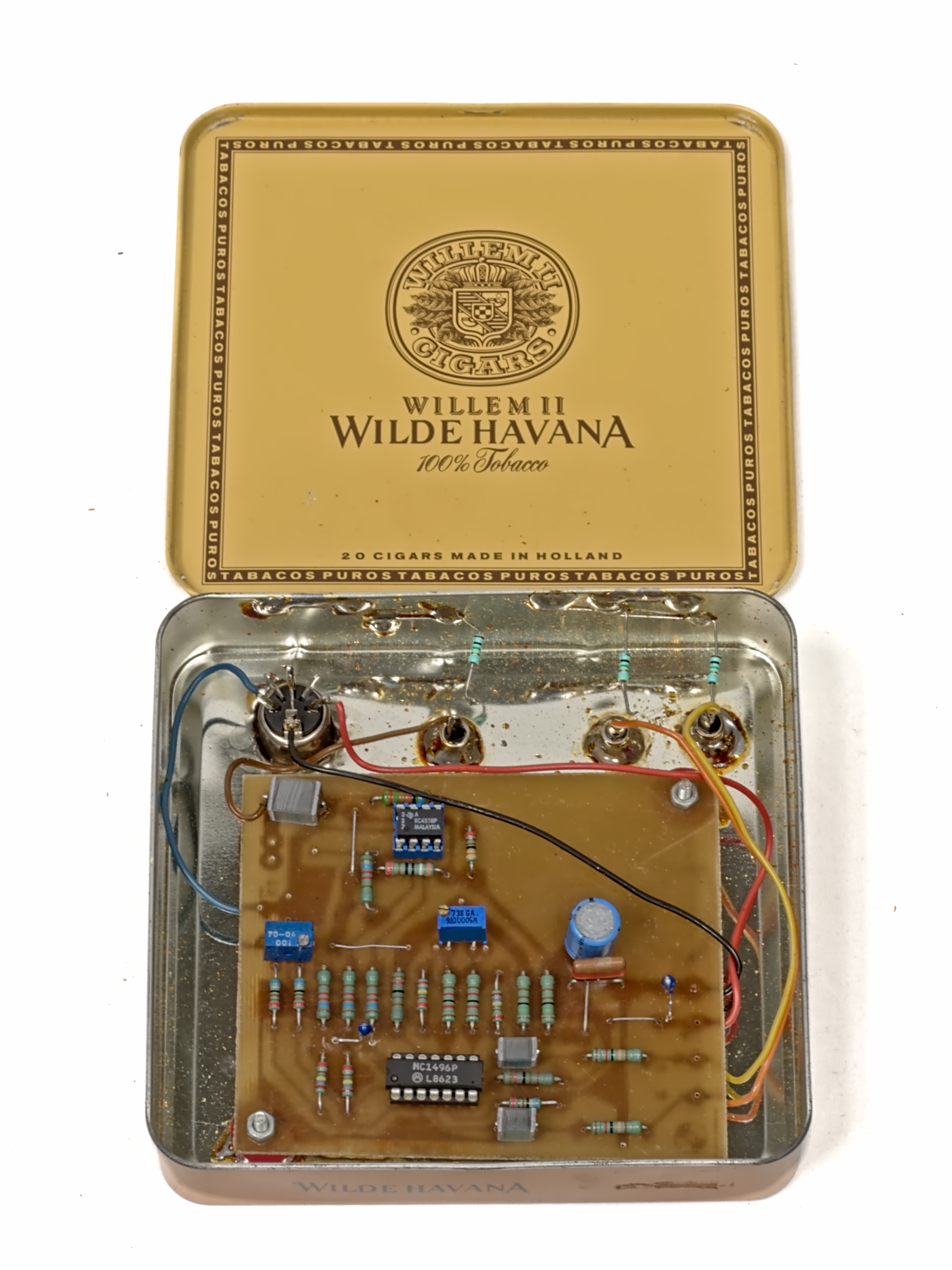
Although the original ringmodulator -or with its more technical name the double balanced modulator/demodulator- was build using transformers or coils, nowadays we would invariably make use of specialised analog chips. Of course, digital implementations are also possible and have become even commonplace as there is no material cost involved.
Usefull analog integrated circuits are:
LM1496 of LM1596 (Philips, National Semiconductor e.a.)
HA2546, HA2547, ICL8013 (Harris)
AD532, AD534, AD539, AD632, AD633, AD743 (Analog Devices)
MPY534 (Burr Brown)
Good quality chips (with 0.5% precision) combined with a wide frequency bandwidth are not cheap. The MPY534 used to go for some 150 Euro. If you can live with 2% precision, you can go for the AD633 and expect to pay ca. 20 Euro.
`
Ringmodulators seen from the perspective of historical performance practice, make us think about the differences between period-circuits versus modern (software based) alternatives.
Other than in the case of tape-recorders, here the physical appearence on stage of the ringmodulator has no importance at all. It can take just about any shape. Most often it's just a metal box with some audio connectors and at the most, a few potentiometers to set levels. The musical result though may turn out very different, for one or more of the following reasons:
- analog ringmodulators 'suffer' a lot from leakage: that is, feed-through of the original inputs to the output. Most of the time, there is a noticable difference in leak-through, between the one input and the other. That's why inputs are often labeled 'signal' and 'carrier', or anything similar to make the distinction.
- analog ringmodulators have a very limited signal to noise ratio
- analog ringmodulators may distort the signal in quite some other ways than what is to be expected from the multiplication process on itself. The dynamic range of the device is inherently limited. The reason is simple: if we multiply two signals with their maximum allowable level, say 10, then the amplitude range of the output ought to cope with the product, say 100 in our example. This inherent -20dB reduction can be compensated for, but always at the detriment of signal-noise ration. This remark, by the way, also applies in full to the digital implementation. However in a digital implementation, we can often anticipate and provide in a much higher bit-resolution at least for the input and modulator signals.
Wherever composers wanted to get rid of feed-through, they most often recursed to gating circuits, designed such as to oppress the output whenever no signal was present on both inputs together.
Bibliographical references:
- ORTON, Richard "Ring Modulator" in: Groves Dictionary of Musical Instruments, dl3.,p.249 (1984)
- BODE, Harald "The Multiplier type Ringmodulator in: Electronic Music Review,nr.1, 1967
- STRANGE, Allen "Electronic Music" ed.:New York, 1972
- RAES, Godfried-Willem "Een Onzichtbaar Muziekinstrument" , Doktorale dissertatie R.U.G., Gent 1993.
Modern practical circuits for analog ring modulators:
LM1496 circuit
zie: Elektuur, Formant-boek, deel 1 & 2
AD633 circuit with balanced power supply:
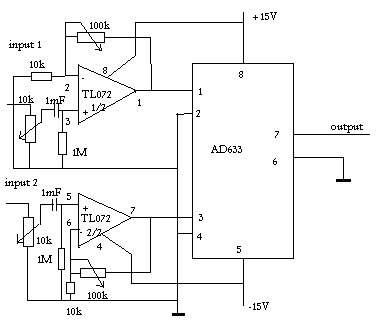
[ref.:93-04]
Here only two chips are used. The first one is a cheap dual operational amplifier. This serves to match impedances to the AD 633 multiplier chip. The 1uF blocking capacitor on the inputs is perfectly o.k. for audio use, but if the use as a VCA is anticipated, these capacitors should be replaced with wire bridges. This will of course lead to a potentially strong DC offset on the output. The input signals for this circuit should not go beyond 10Vpp. As the dynamic range of the output can be very high, it is often advisable to let the circuit be followed by a limiter or even a compressor circuit.
 |
This article is part of a research project on Experimental Legacy financed in part by the Orpheus Institute in Ghent. Last update: 03.10.2022 www.orpheusinstituut.be |