Midi Soup
1.- MIDI via ethernet UDP/IPWorking proposals for a protocol that can replace standard MIDI with possible extentions, a manifold speed benefit and wherefore the receivers can be implemented on small microcontrollers.
2. - Overcoming hardware troubles with MIDI
Wiring alternatives compatible with MIDI but without its limitations.
dr.Godfried-Willem Raes.
Introduction:
The many problems related to MIDI are a burden to many designers, composers and musicians. So we will not deeply enter into the vast area of justified complaints in this regard. This paper proposes two different way-outs. Our personal prime reasons to look into alternatives for standard 5p-DIN-wired midi were:
- 1.: to overcome the 16 channel limit. Even using 8-ports we still only had 128 channels.
- 2.: to overcome the slowness of midi, due to its low baudrate of only 31250Baud
- 3.: the limitations on bidirectional real time data exchange.
The secondary reasons, dealt with specifically in the second chapter, have to do with the weakness of the midi-thru hardware implementation where we invariably run in trouble when passing MIDI through a cascade of optocouplers. These problems came out as very severe and really asked for an urgent fix in the context of our ever growing electro-mechanical robot orchestra housed at the Logos Foundation in Ghent, Belgium.
1. Ethernet experiments:
The very first suggestion coming up was going for DMX, a technology very similar to Midi but running at the double speed. The main property that makes DMX attractive seemed however, more so than the speed advantage, the allowable cable lengths of over 100m. This is because DMX is usinjg true differential signals instead of a unipolar current loop. At the other hand, the existing standards whereby channels are continuously scanned, seemed as such not very suitable for fast real time applications. The net gain of this technology was too marginal (if any...) to make a practical implementation worth the effort.
Then, after checking possibilities via USB 2.0, we rejected this completely because of the shaky so called' intelligent' mode of the operating systems at the one hand (leading to having to reinstall drivers every time again the OS refused to 'recognize' the non-Microsoft approved device...) and the strong restrictions on cable length at the other. (USB is even far worse than Midi in this respect. Dont even dream of a USB cable 20 meters in length...).Then entered ethernet into scope. First we attempted to use TCP/IP but found the jitter musically completely unacceptable. Delivery of data packets was just not deterministic enough to be usefull in real time and interactive applications. For this experiment we set up two laptop PC's: one generating notes via its internal soundcard and outputting the same, shifted a fifth, via TCP/IP. The other receiving the data packets and outputting them in turn via its internal soundcard. We could simply never get them to play really together...
Next we checked out UDP/IP. Under specific conditions, this came out as a workable alternative. The conditions being that one should use a dedicated network without external connections eating network bandwidth. Based on mere bandwidth capacity one would assume ethernet at 10MB being a factor 300 faster than Midi, but this factor gets reduced by the fact that minimum data packet size in UDP seems to be 28 bytes, versus 2 or 3 bytes in midi. Thus the actual speed gain is rather in the order of 30 times. If we further take into account our wish to support at least 128 channels, than the net performance would only be 3.75 times faster than plain old midi... Of course we could go for 100MB or even 1GB ethernet, but the non availability of small microcontrollers to support these speeds made us (at least as far as technology stands now) stick to 10MB. This speed can be handled with the newest generation of Microchip PIC controllers, our favorites for building our musical robots and automatons.
The first experiments were carried out using a PC-type master laptop server with a 16 port hub. Each of our midi-controlled robots was given a workstation laptop running a UDP/IP data communication program written in our own GMT language (a superset of PowerBasic) translating the UDP packets back into midi. (On some of the older robots we could translate directly into the parallel bus they had, using the laptops printer port).
When we look into a standard midi command such as note on, this is coded as a data stream in following format:
velocity byte note status + channel 0xxx xxxx 0xxx xxxx 1010 xxxx (This is the big endian byte order as used by the Windows midiOutShortMsg function.)
In our GMT language we already extended the number of possible channels, by using multiport devices. To implement this, we placed the status + channel byte into a word (16 bit) variable, wherein the high byte of that word contained the port number. So the structure of the channel-word became:
not used (always reset) port nibble status nibble channel nibble 0000 pppp ssss cccc It shall be clear that this way it was easy to implement 256 midi channels using midi-multiport devices such as MidiMan 8x8. The reconstructed byte ppppcccc returns the channel.
The new wrapper for the note playing command in our software thus became:
FUNCTION mPlay (BYVAL channel as WORD, BYVAL note as byte, BYVAL velo as BYTE)
For the UDP experiments and evaluations, we used the high nibble of that word as a pointer into a list of IP adresses. Thus the meaning of the binary component of the status word became:
IP-adress pointer in list port nibble status nibble channel nibble nnnn pppp ssss cccc The nnnn nibble is a pointer into a list of binary encoded IP adresses, wherein the usual notation 255.xxx.xxx.xxx (or similar) becomes &Haabbccdd, packed into a single unsigned word variable.
The UDP send command, replacing former midi now becomes:
UDP SEND porthandle AS DWORD, AT segment_ip(nnnn), udp_port(nnnn), BYVAL msg AS STRINGThe msg message string thus sent, is -apart from the string format in the declaration, identical to the normal midi bit sequence as sent out by the midi functions.
The wrapper for midi via UDP becomes simply:
FUNCTION g_net_send (BYVAL msg AS STRING, BYVAL nr AS DWORD) EXPORT AS LONG
Up to 2004 most of our musical robots used a dedicated laptop computer for communication and control So there was always a hassle in setting up the IP adresses and keeping the ini-files up to date. Since 2007 all robots have there own (ofter very many...) small microcontrollers translating the midi commands into whatever is required for the automatons. To implement midi over UDP/IP we now are developing small boards with an ethernet connector and two midi DIN connectors, to allow bidirectional communication. The IP adresses for each board, and therewith for each robot, are hard encoded in the firmware and can be different for each robot. The advantage to use bidirectional data links is in the first place to overcome the intrinsic deficiency of UDP (as compared to TCP) in dealing with lost packets. Now each robot can (optionally) send its status back to the server, or -if usefull- to any other robot on the network segment. For musicians dealing mainly with pure electronic instruments or samplers this may sound a bit silly if not over the edge, but remind you these are electromechanical robots sounding purely acoustical. For instance, our bass accordion (<Bako>) has a motor to move the bellows up and down. De direction of the movement is under midi control but a sensefull musician will let the requested direction of the movement depend on both the actual bellows position and the durational rerquirements for the note he wants to play. Hence this robot outputs the position of its bellows via midi, and soon, via UDP...
----------to be completed and followed up ------------.
On the receiver side, in our case mostly the dedicated microcontroller built into any particular robot, the UDP-receive function returns data with regard to the sender (the IP adress) as well as a data packet than can be directly relayed to the midi-out port, if the channel matches the channel for the robot and if the message is acceptable to the robot. This way the risk of overflowing the midioutput with more data than the midi serial format is capable of handling, is seriously reduced. However it remains possible. So, the microcontroller should provide as much as possible of its (very limited) memory as a buffer. On buffer overflow, the microcontroller can output a warning message via UDP send using its unique IP adres to the server.
Quartertone music
An increasing number of our automatons is tuned in quartertones:<Qt>, a 6-octave quartertone organ, <Tubi> a tubular quartertone metallophone, <Puff> a quartertone percussive puff-organ, <Xy>, a quartertone 3.5 octave xylophone... To use these instruments using standard midi, we provided each of these with two subsequent midi-channels. The lowest channel for playing the 'normally' tuned pitches, the higher channel for playing the quartertone pitches. This seemed to be the most elegant solution within the limited musical world (12-tone, monometric - remind you the Midi File Format 2 was never properly implemented...) covered by the midi standard. This, of course at the cost of already way too scarce midi channels.
Non-real time midi transfers
Most of our robots have an implementation for system exclusives, allowing users to program lookup tables for velocity scaling, pitch remappings and such more. To implement this with ethernet, we would rather use TCP/IP, since sysex dumps should never be done in real time or during interactive composition performances.
2001/ 2007
2. Improvements whilst maintaining compatibility with standard midi I/O ports:
In 2013 we undertook a project for a complete hardware revision of MIDI data transfer. However, we wanted to preserve standard MIDI compatibility for all the individual robots, thus the optocouplers and the 5mA current loop driving a midi input ought to be preserved. The reasons behind the revision were: First of all, to overcome the signal degradation caused by the pass through way too many optocouplers we were experiencing in our work with the robot orchestra, at this point (august 2013) consisting of 56 musical robots. Second, to solve the problems with cable lenghts, limited to 10 meters in standard MIDI.. Symptoms for signal deterioration are typically: missed note-off commands: stuck notes. The binary midi code for these commands contains a long series of 0's and the receiver UART tends to get out of sync. If you are not immediately convinced, look at the binary equivalent of the code sequence for note 64 off on channel 0: 1000 0000 0100 0000 0000 0000. The slightest bit of jitter on the only two one's in this train will guarantee you a missed command.
In this new design we use true differential bus transceivers, more specific SN75176 components and implement a RS485 protocol with the MIDI baudrate. The A and B output lines (if configured as outputs by bringing pins 2 and 3 high) can directly drive a traditional midi-input with its optocoupler. Line termination can become an issue and if the outputs are not driving a midi opto-coupler, it would be best to have a 220 Ohm load resistor soldered between DIN pins 4 and 5 on the input. Midi signals are too slow to consider the wiring a real transmission line requiring proper termination, but to maintain the steepness of the square wave signals throughout the transmission we concluded thats is much better to just do so. Obviously normal midi cables do not have a specified characteric impedance, so the value of 110 Ohms is rather arbitrary and only chosen to match standard CAT5 cables.
For long lines we designed following circuit allowing to run 4 midi ports (good for 64 midi-channels) via a single standard CAT5 or CAT6 Ethernet cable with RJ45 connectors.
So with two of these circuits (in fact the receiver and the transmitter make use of the same PC board, with only a few jumpers placed differently) we can have our 8 port midi device active on any reasonable distance. The midi-in violates the MIDI standard in that there is no optocoupler. In fact we maintain the optocoupler only at the very end of the signals destination, that is on the robots themselves. The only remaining problem is that the differential inputs do not work with standard midi, the standard midi-out signal being inherently non balanced. As long as we do not use differential receivers on standard midi-out's the problem can be circumvented.
A note of warning: if using differential inputs, make sure the input is driven by a cable with properly defined voltage levels when the circuits are powered up. When the inputs are left floating (not driven by any signal or defined state), the outputs may become unstable and glitch. A circuit that circumvents these problems, as it will make the outputs high impedance if no differential signal is present on the inputs look like this:
When the green LED lights up, the differential signal is o.k.
The overview of the robot network, completely using differential lines, now looks like this:
The hubs as well as the buffers use SN74174 quad differential drivers. The buffers have true differential inputs using the SN75176 chip whereas the hub's receive a TTL midi signal directly from the midi-interface. All circuitboards have individual floating power supplies, so ground loops cannot occur. Readers interested in building up these circuits can make use of our PCB designs. They are single sided boards and can easily be produced at home. They should be printed at 50% scale on transparent film as used for overhead projectors.
Here are the links to the PCB files:
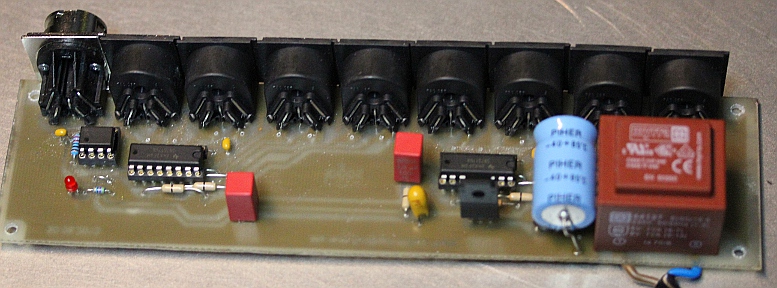
- HUB board: 1 input, 8 differential outputs
Here is a picture of this board:
(This board wired for operation without opto-coupler on the input).
- BUFFER board: 1 differential input, 8 differential outputs
Here is a picture of this board:
- BUFFER board: 1 differential input protected against floating lines, 8 differential outputs
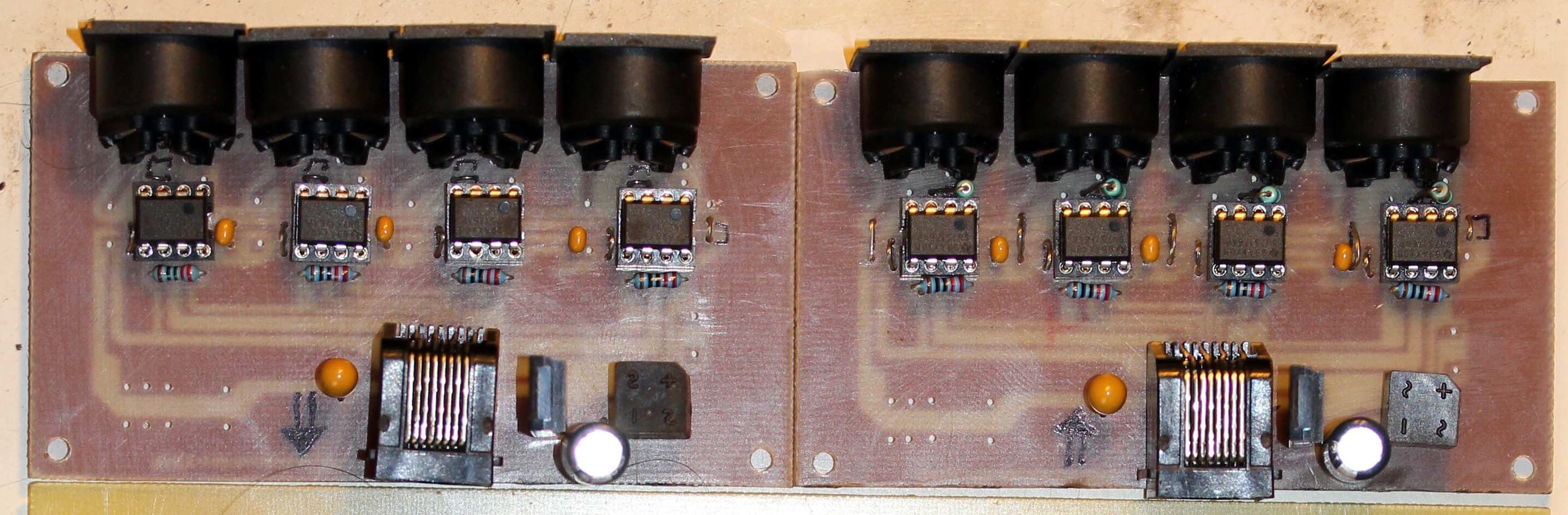
- Quad line tranceiver board (can be configured either as driver or as receiver) for RJ45 connector and CAT5 cable. A couple of these boards -one wired for output, the other for input- can be seen in the picture below:
Collaborators on this project:
- Johannes Taelman (Microchip PIC programming)
- Yvan Vander Sanden (Linux o.s. implementation)
- Kristof Lauwers (Midi file player development under PowerBasic/GMT)
- Mattias Parent (board assembly and production)
- dr.Godfried-Willem Raes (hardware design, project management)
last updated:May 1, 2014
dr.Godfried-Willem Raes
