Prof.dr.Godfried-Willem RAES
Course on Experimental Musics: Book 2: Live Electronics
Hogeschool Gent : Departement Muziek & Drama
|
Due to the technical nature of this page, we only have an english language version. |
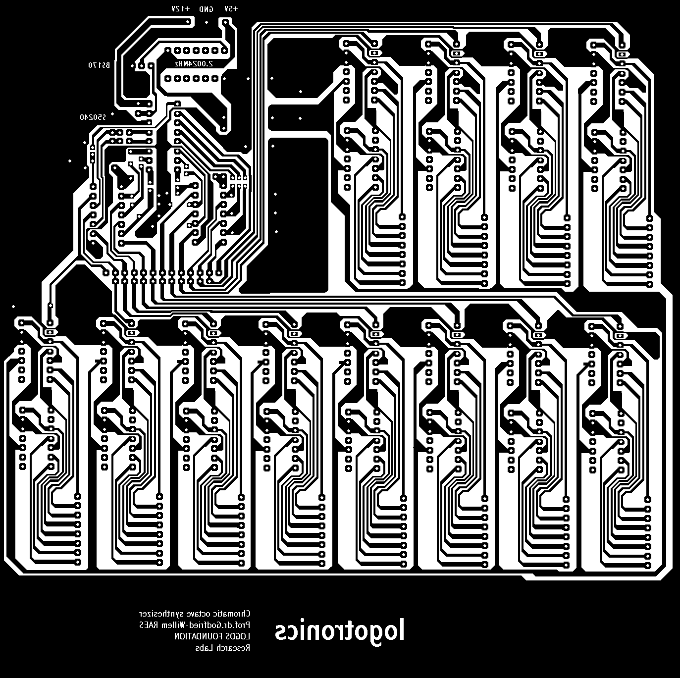
PC-board layouts can be found at the bottom of this page. |
This page describes the electronic aspects of the design of a synthesizer circuit that delivers up to 128 individual and switched note frequency outputs. These can be used to drive exciters for physical objects. Solenoids or other electromagnetic devices can be used to this end, but piezoelectric devices are an option as well. The circuits can be controlled by midi-commands, extending further the material presented in previous chapters. (2071). Software support is integrated in our GMT-programming language for real time music composition.
For this design we started with the selection of a so called 'top-octave' synthesizer chip. This is basically an integrated bank of 12 or 13 dividers, dividing a common clock signal such that at its 12 or 13 outputs we get a full octave of equal temperament intervals. We choose an oldy for this purpose: a S50240 chip, since we had a bunch of them sleeping on our shelves since the mid seventies. The chip was produced by different manufacturers under names ssuch as: S50240P, MK50240, AY3-0215, AY3-0216. The division factors for this chip as given in the specs are:
The clock frequency (pin 2 input) should fall within the range of 100kHz and 2.5MHz. So, if we want to obtain frequencies tuned to A=440 with the notes gives in the table, we should use a clock frequency of 2002400 Hz or 1001200 Hz. (Note: although the spec sheet gives 100kHz as lowest frequency, we tried frequencies at least a decade lower without any problem).
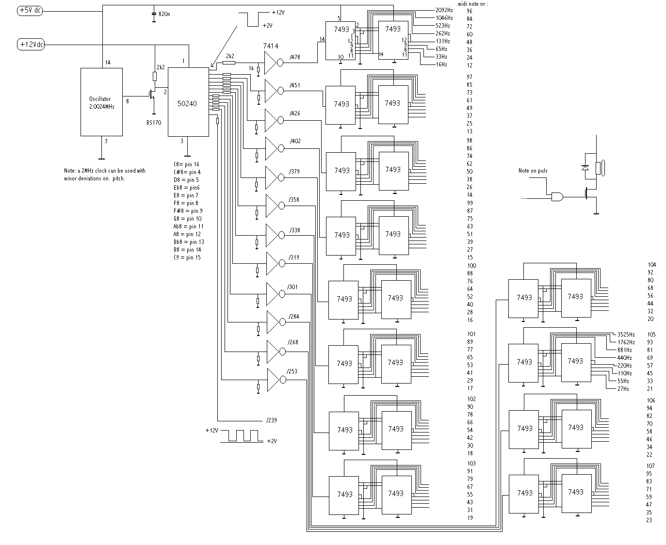
However, when using this chip, we have to overcome some slight design problems: first of all, this is NOT a TTL chip. The clock input should be -5V pulses, going negative and all outputs are negative pulses, not reaching a standard logic 0 level. Interfacing to the 40xxx series of MOS logic chips was easy, but obviously we wanted to convert all this to regular TTL levels. We started by grounding pin 3 and putting +12V on pin 1. When a normal solid state oscillator is used (a small metal can type), we have to convert this output to something pulsing down from the +12V supply line. Hence we introduced the BS170 mosfet, to create a suitable clocking signal. The outputs now switch between +12 and +2V. So, in order to bring this to TTL, we used a resistor divider 2k2 and 1k and send the attenuated outputs to our schmitt trigger inverters. The only nasty thing left in the design is now the requirement for an extra +12V power supply. (We tried to operate the chips on a lower voltage, but below 9.5V it stop functioning...). If no convenient source for this voltage is available in your application, consider using one of these very small DC-DC step up converters that are available from many suppliers nowadays. The divider draws at the most 15mA.
To generate all notes required for a complete instrument driver, we have to add dividers to generate the note frequencies in all octaves required. So we choose 2 cascaded 74HCT93 dividers for each note frequency. We buffered the synthesizer chip outputs using two 74HCT14 hex schmitt-trigger inverters, as said before. Some twenty years ago we could have done this easier, by just feeding the synthesizer outputs directly in a CMOS 4024 divider, offering us 7 octaves directly, but these chips are no longer on the market. Also it would have led to further problems, since the octave divided outputs would not be at TTL levels.
So doing we obtain each note frequency in 8+1 different octave positions. In total, good for 108+1 = 109 notes. Now, if we would connect all these outputs to keyboard switches and mix all outputs together, we would have build an old-technology electronic organ (we would have to add some formant filters, for registration). However thats not our pupose here. We do not want to mix the outputs but instead, use each note output frequency to drive any kind of mechanical object. Conceptually this is not principly different from building an organ with as many loudspeakers as there are notes, thus eliminating completely any kind of intermodulation distortion. Here, we wanted to use mechanical objects that would be very frequency specific, such that the objects are in resonance with the frequencies we feed them using our output devices. As to the objects, there are many possibilities. To name just a few: membranes (metal or plastic), styrofoam blades, pneumatic valves, strings, clamped rods... Note that precisely this property makes this design unreplacable by anything available on the market.
The circuit for the frequency synthesizer became:

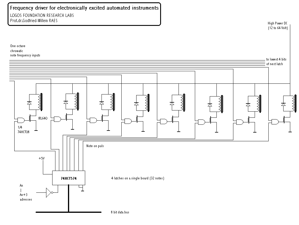
The driver circuit uses these frequency outputs, fed to a AND function (74HCT08) together with a note on signal derived from either the Midi UART board presented in the previous chapter, or from our automated instrument demultiplexer boards using the printer port, USB ports or National Instruments PCMCIA cards, treated further in these chapters.
The circuits for the mosfet drivers look like:

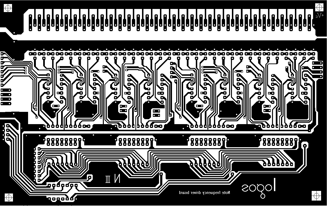
We designed general purpose prototype PC boards for both circuits. You need only one board for the frequency synthesizer, whereas for the driver boards you need one board for every 2 1/2 octaves (32 notes for each board) you want to implement.

Of course, there are many more possible applications fir this synthesizer board: it can serve as a tuning reference, you could FM modulate the clock input and get a simple FM synth...
The driver boards came out as follows:

Note that all artwork is done on a 200% scale. (Save the GIF files and print them out on transparencies at 50% size).
Final remark: if anyone out there knows of a modern chip -not a processor- that performs the 12th root of 2 divisions required for a top octave synthesizer, please let us know. Many people already asked us for replacements, but sofar we could'nt trace any.
Filedate: 2008-04-28
|
Terug naar inhoudstafel kursus: <Index Kursus> |
Naar homepage dr.Godfried-Willem RAES |