Prof.dr.Godfried-Willem RAES
Course on Experimental Musics: Book 2: Live Electronics
Hogeschool Gent : Departement Muziek & Drama
|
Due to the technical nature of this page, we only have an english language version. |
PC-board layouts can be found at the bottom of this page. |
This page describes the electronic aspects of the design of a musical robot controlled by midi-commands. It builds further on the material treated in the previous chapter (2071). Software support is integrated in our GMT-programming language for real time music composition.
The purpose of the design presented here is the development of the necessary circuits capable of controlling individually 512 (4 banks of 128) solenoids, electric valves or whatever kind of load required in the automat. These loads can be switched using any kind of standard midi 3 byte message. However, since the midi data bytes are only 7-bits, we had to violate the midi rules a bit . Thus, in order the obtain a 8-bit databus, we borrow bit 6 from the msb to serve as bit 7 for the bus. The remaining 6 bits will be used as adresses. Each adress points to an 8-bit latch.
| byte 1 | byte 2 | ||||||||||||||||
| - | b6 | b5 | b4 | b3 | b2 | b1 | b0 | - | b6 | b5 | b4 | b3 | b2 | b1 | b0 | ||
| - | - | b5 | b4 | b3 | b2 | b1 | b0 | b7 | b6 | b5 | b4 | b3 | b2 | b1 | b0 |
The circuit for the UART receiving the midi data, decoding them and converting to parallel format is the same as treated in the previous chapter. The PC board however is a bit different as we added two 8-segment displays to facilitate debugging and testing.
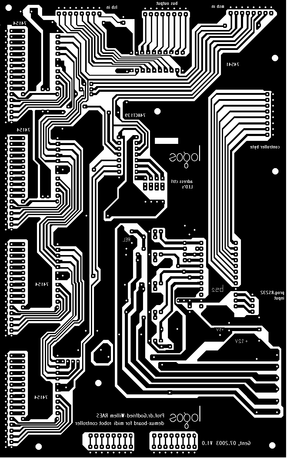
The two 7-bit bytes are connected to the input of the demultiplexer . The PC board became:

On this board, we found place to add a Paralax Basic Stamp ( a BS2) that can be used to read the 1 byte midi message (program change). As shown here the Stamp has 4 outputs steering power mosfets. Depending on the software loaded in the Stamp , this circuit can be used to controll a stepping motor, a 3- or 4-phase AC motor or similar stuff. One extra output can we used to steer a relais such that the power supply for the mechanical parts is only switched on after reception of a pin code. The connector in the middle on the upperside of the board has the 8-bit databus. The decoded adres lines ( 4x 16 lines) are available from the headers on the left side of the board.
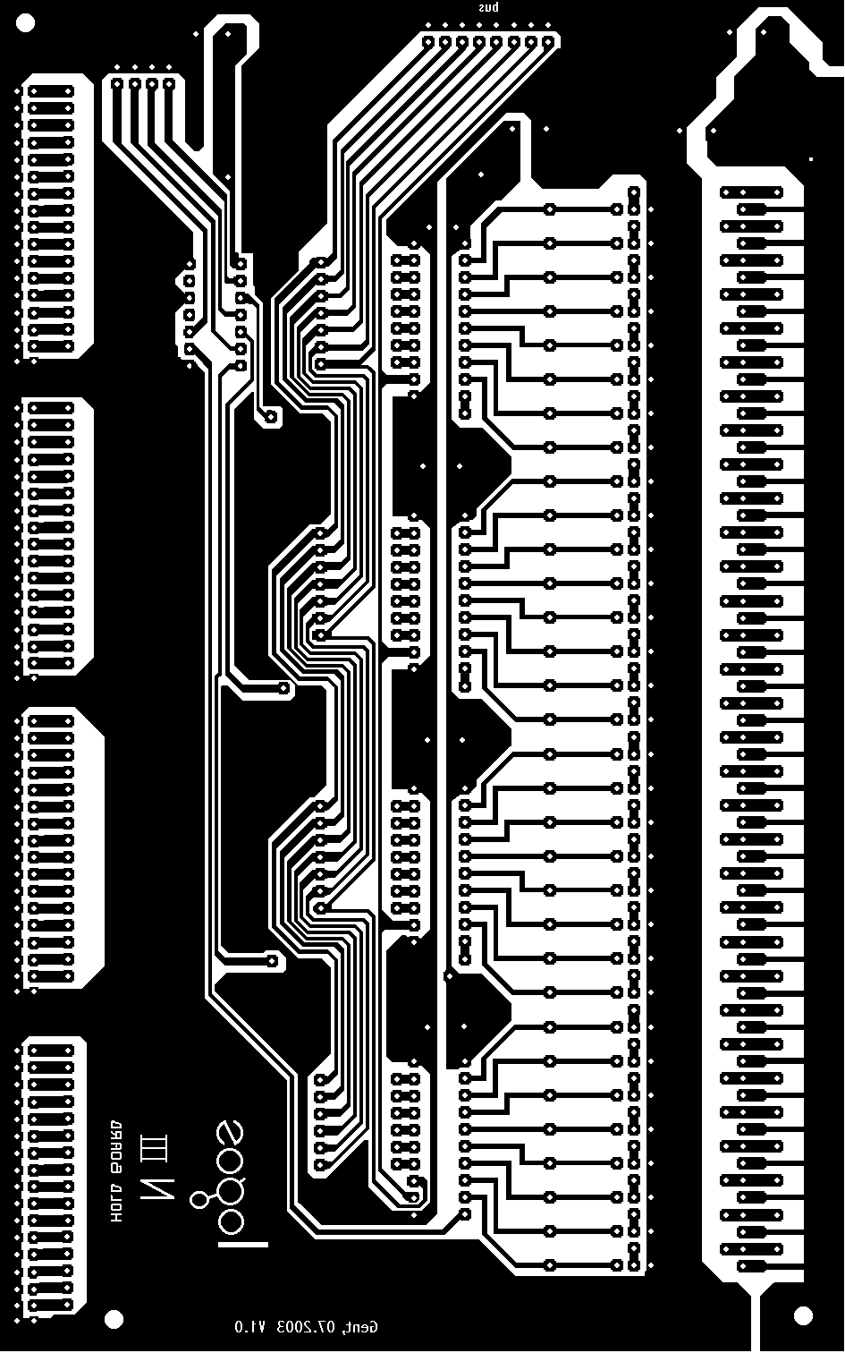
In its turn, this board is connected to the notes latches and mosfet drivers. These boards can accomodate up to 32 drivers each. So for a 128 note instrument, we need 4 boards. The maximum number of boards that can be connected is 16, good for a 512 note instrument.

Of course, with hardware alone we cannot make a functioning robot. We need mechanical parts and, last but not least, software support.
Here we give a code snipped for a procedure (a part of the midi support section in our GMT-library g_lib.dll) that can be used to send the correctly formatted data in midi format to the hardware described above:
SUB MiRobotPlay (BYREF Robot AS musician) EXPORT
' uses non-standard midi, in combination with our special purpose hardware. We need Robot.channel (see structure definition file g_type.bi). We will need a select case structure here to implement the different midi-controlled robots we might build. For now, this is just a working generic procedure. STATIC tog AS DWORD
STATIC ShortMessage AS DWORD
STATIC h AS DWORD
LOCAL i AS DWORD
LOCAL j AS DWORD
LOCAL ib AS BYTE
LOCAL vb AS BYTE ' velobyte - used as databus
LOCAL nb AS BYTE ' notebyte - used as adresbus
STATIC sb AS BYTE ' status byte
DIM latch(15) AS LOCAL BYTE
LOCAL p AS DWORD
IF ISFALSE tog THEN
DIM olatch(15) AS STATIC BYTE ' previous contents of the latches
h = robot.channel
SHIFT RIGHT h, 8
h = hMidiO(h)
IF ISFALSE h THEN EXIT SUB ' no midi handle, so we cannot proceed.
sb = 144 OR (robot.channel AND &H000F) ' set with the dip-switches on the hardware. (UART board)
tog = %True
END IF
p = 1
FOR i = 0 TO 15 ' we can limit this to the actual range used.
FOR j = 0 TO 7
ib = ASC(MID$(Robot.Har(1).vel, p, 1)) ' new harmony string
IF ib THEN
BIT SET latch(i), j
ELSE
BIT RESET latch(i), j
END IF
INCR p ' counts 1 - 128
NEXT j
IF latch(i) <> olatch(i) THEN
nb = i ' uses the lowest 4 bits (0,1,2,3)
' for the higher registers we have to use bits 4 and 5.
' bit 6 is used as 8th bit for the databus.
vb = latch(i)
IF BIT (vb,7) THEN
BIT RESET vb,7 ' so we stick to the required 7-bit length in midi.
BIT SET nb, 6 ' we pack the 8th bit in the highest possible bit of the second byte
' the decoding and reassembling is done in the hardware of our boards.
ELSE
BIT RESET nb, 6
END IF
' now we have a new byte available, so we can send it (max. 8 notes at the same time!). Note that the midi-drivers expects the bits as lsb - msb - status, so 24 bits, big endian.ShortMessage = vb
SHIFT LEFT ShortMessage ,8
ShortMessage = ShortMessage OR nb
SHIFT LEFT ShortMessage , 8
ShortMessage = %MEVT_F_SHORT OR ShortMessage OR sb
midiOutShortMsg h, ShortMessage ' winapi call, of course we have to open the midi port first!
olatch(i) = latch(i)
ELSE
' nothing
END IF
NEXT i
Robot.Har(0).vel = Robot.Har(1).vel
Robot.Har(1).vel = STRING$(128,0)
END SUB
Filedate: 2003-06-30
|
Terug naar inhoudstafel kursus: <Index Kursus> |
Naar homepage dr.Godfried-Willem RAES |