|
< Vibi >
an fully automated vibraphone |
|
Godfried-Willem RAES 2001 / 2005 / 2010 |
|
< Vibi >
an fully automated vibraphone |
|
Godfried-Willem RAES 2001 / 2005 / 2010 |
Most certainly, we are not the first to have automated the vibraphone. We recall very well the extensive work done in this field by our friends -at that time in Baltimore- Carney and Alec Bernstein. But sure enough, many more instrument builders have undertaken this task before. Of course we are not forgetting the many pneumatic implementations found in some of the large dance organs (orchestrions) from the interbellum (Mortier, Hooghuys, Decap, Limonaire....) of vibraphones, xylophones, glockenspiel etc..., although these were pneumatic and pretty primitive, lacking fine dynamic control. So, when we started our own attempt to realize an automated vibraphone, we could build further on these experiences and take off from there.
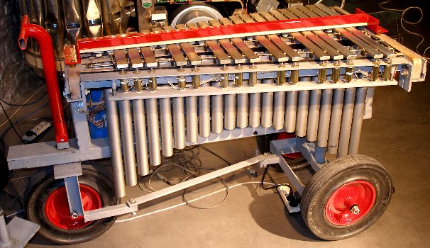
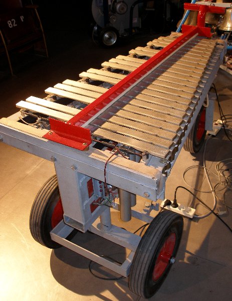
Our own design had to become a computer controlled acoustic vibraphone with touch control and individual dampers for each single bar. The starting point for the practical construction was an small model Yamaha vibraphone (type YV-600B, serial number 1977) ) of which we only kept the tuned aluminium staves and the resonators. The original global damping mechanism (activated by the pedal) was thrown out altogether. A new electric circuit was designed for the vibrato mechanism, since the original one was too noisy and could not be easily computer controlled. As an extra bonus -not found on any commercially existing vibraphone- we wanted the flap valves for the resonator tubes implemented not only as a rotating vibrato mechanism, but also as a volume control. This entailed precise control of the position of these valves as well as a return to a determined position after a period of normal rotation.
The beaters make use of Lukas Ledex solenoids (similar as the ones we used for our player pianos), mounted under the extremities of the sound bars. The dampers were made with the same type of solenoids, but here we mounted rubber or felt pads on the anchors as dampers. No springs were used. The anchors falling back on a heavy felt covered steel bar by gravity alone. The design started off with an analysis of pulse timing requirements for the automated vibraphone:
The attack pulse tv1.tv2... (for power supply voltage of 44V -see further) should range between 3 ms and 15 ms. If we want good dynamic controll, it is enough to controll precisely the pulse width of the attack solenoids with the beaters. The pulse duration for the dampers (td) could be constant and, if so, equal to the minimum pulsewidth required to damp the bar (ca. 50 ms) . At rest, the damper can be released, so no power is spoiled. The maximum repetition speed will be dependent on the dynamic used and is limited anyhow by the time required for the beater to fall back plus the time for the damper and the time for this damper to fall back. Of course, when playing very fast repeated notes one could decide not to use the dampers. But even than, the repetition rate will be determined by the time it takes the beater to fall back. If we mount the anchors with springs, the fall back time can be decreased, but only at the detriment of dynamic range: the heigth of the (compressed) spring should be subtracted from the original movement traject. Also springs unavoidably introduce their own resonant frequency, interfering with some specific repetition rates.
This design offers many more musical perspectives than either what musician playing vibes could have to offer. First, it is truly polyphonic with complete autonomy for the individual beaters. So no longer a limitation to 2 ,4 or if conservatory acrobatics are used, 6 notes/sticks. Second, as we provided individual dampers for each bar, the musical possibilities in terms of expressive refinement are greatly enhanced. Third, since we finally decided to also implement velocity for the dampers, we can control the damping up to the smallest detail. This way even the most 'avant-garde' playing techniques can be realized on this automate. What we have not implemented is changes of sticks, as musicians are often required to do in typical contemporary music pieces. This would have required at least yet another row of solenoids with softer beaters. There is barely enough space under the bars to allow for such an untertaking. Of course we could place them above the bars, but then one potential element of magic in the instrument would disappear: the possibility of manualy playing the instrument at the same time as its automate plays. Nevertheless it requires the user only to exchange all 37 beatercaps if it is realy required to sound this vibraphone with a softer (or harder) attack.
A new element in the design of this robotic instrument is that we implemented a damper-hold mode, whereby the felt covered dampers can be pushed against the staves with a continuously variable force. Thus the staves can also be played whilst damped to a variable degree. It was easy to implement this since 8254 type timer chips can be programmed to operate either as programmable one-shots or as square wave generators. In the latter case, since their outputs drive the solenoids via mosfets, we take profit of the fact that the coils impedance rises with the frequency of the applied voltage. Thus the current through the solenoids can be controlled by programming the periodic frequency of the timer chips. At some operating frequencies in the audio band however, this operational mode can lead to audible noise stemming from the solenoid anchors. This possibility however is only available when controlling <Vibi> with a laptop of its own. The midi-input version has no support for this operational mode.
As usual in our instrument designs, we constructed TIG welded steel frames for the entire magnet and electromechanics assembly. Bolts on the sides of the instrument in combination with the bolts holding the fallback bars under the solenoids, allow for fine adjustment of the traject of movement for the beater and the dampers. This affects the dynamic range. The instrument was mounted on large and very sturdy wheels of the same type as used in most of our other first-generation robots that make up the Logos robot orchestra.
The note range of the instrument is 37 notes, 60 to 96 (C-c") expressed in midi notes.
For the electronic control of this instrument we used hardware we originally designed for player pianos. Originally the instrument was played using a Wintel Pentium PC. The demultiplexer for the parallel input is a left over from this original design although now it is controlled by a PIC microcontroller taking input from MIDI data directly. The demultiplexer looks like:
The note driver board and the velocity controll circuitry was build after following schematics, using intel 82C54 programmable timer chips, used as programmable one shots in this application. The pulse width, using a 1MHz clock, is programmable between 1 microsecond and 64 ms. The practical (and musically relevant) range used and set in the software is 3.5 ms to 16 ms. We use the following formula for the rescaling of midi velo values into microseconds: pulse = 2048 + (velo * 128/4) + (velo^2 / 4). This was implemented in the PIC firmware. The dampers use a different mapping.
bus-demultiplexer PC board lay out
(These PC boards -without components- could be obtained against
cost from the author for many years. Now the design is replaced by a newer ones,
but occasionally you may encounter one of these boards as we sold quite a few
of them). One board accomodates one octave. .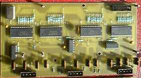
The solenoids used are: Ledex STA series push tubular solenoid type nr. 195207-228. They have a cold DC resistance of 19.1 Ohm. The nominal working voltage, at which the coils can be activated indefinitly long is 13.8V. At 10% duty cycle, a voltage of 44V may be applied.

motor board:
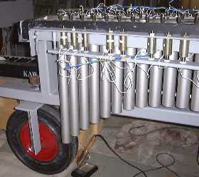
The resonators, as usual on a vibraphone, have a rotating mechanism allowing
them to be periodically opened and closed. Each row of resonators has its own
rotating shaft. So we provided 2 stepping motors, such that rotational speed
of upper row and lower row can be controlled independently over a wide range.
To achieve this, up to 2010, we used the two 8-bit auxiliary ports on our demultiplexer
board to controll two PIC microcontrollers. Thus the software could suffice
by sending a byte (0-255) to control the rotation speed of the motors. The original
code, microcontroller basic, for the PIC's can be found in our Stamp
directory. In 2010 however, we improved the mechanism quite a bit. The first
problem with the original implementation was that whenever the motors were stopped,
the end position of the shutters was unknown and arbitrary. Proximity sensors,
such as used in our design for <Korn>, thus were added in the new design.
Now the motor can be stopped in a predetermined and programmable position. Also,
we were not fully satisfied with the range of the speed control. To improve
this -keeping the same motors- we decided to go for a full bipolar drive using
a small Nanotech motor controller. This increased the torque considerably on
high speeds. The new circuit looks like: 
An overview of the final assembly of all circuit boards used for <Vibi>, looks like:
The power supplies, modified in 2010, now look like:
The wiring of the PIC-board translating midi-input to our parallel bus looks like:
[comments on these circuits, first developed for one of our player pianos can be found at/kursus/2116.html.]


<Vibi> has played at following venues/occasions: Tourcoing (France, Le Grand Mix), Ghent (Logos Tetrahedron), Amsterdam (Paradiso), Herne (Germany, Teutoburgia Halle), KULAK University (Kortrijk), Yttre (Wallonia), TART symposium (Enschede), Festival in de Branding (Den Haag), Adventures Festival (Korzo Theater, Den Haag), Lille 2004 (Aeroneff, Lille), Muenchen 2005, DeAvantgarde Festival (Muenchen), November Music (Den Bosch), Computed Music IV (Koeln), Jauna Muzika Festival (Vilnius, 2007), Orgelpark (Amsterdam, 2008), Dag van de Oude Muziek (Alden Biesen, 2010), STAM-opening (Ghent, 2010), Deutsche Oper Berlin (2023)...
Available repertoire for <Vibi>, alone or in combination with other automats.
|
Tech-Specs -----------------------------------------------Technische specifikaties: Aanvang bouw: augustus 2001 - . <Vibi> speelde zijn eerste toonladder op 9 oktober 2001 en was volledig afgewerkt op 16 oktober 2001. Het materiaal van de aanslagkapjes werd vernieuwd in 2004 en nogmaals in 2024. In 2005 werd <Vibi> omgebouwd zodat hij ook zonder laptop besturingskomputer rechtstreeks midi signalen kan verwerken. Het vibrato mechanisme werd helemaal herzien in 2010. Size-----------------------------------------------------------------------------------------------------------Afmetingen van het afgewerkte instrument:
Power--------------------------------------------------------------------------------------------------------Stroomvoorziening:
Insurance value (for organisors):
Rental / concerts:
|
|
Midi Implementatie: The default midi channel for <Vibi> is set to 10 (if counting channels from 0, otherwize its 11)
|
| Godfried-Willem Raes | <A Last Repetitive>, 1976 | for naked dancer and vibraphone |
| Godfried-Willem Raes | <Vibes for Vibi>, 2001 |
solo composition - environmental music, with optional <Harma> and <Piperola> part. (Premiered on the Polymachina festival, Tourcoing, 2001) Available on CD: LPD008 |
| <Trio Paradiso> | for <Vibi>,<Klung> and <Harma> (Commisioned by Paul Koek, premiered at Paradiso Amsterdam, 12.11.2001) [5'00"] | |
| <Paradiso> |
for <Vibi>,<Klung>,<Player Piano>,<Harma>,<Piperola> and optional musicians [10'30""] Available on CD: LPD008 |
|
| <Eary Lis Trimbl> |
for automat orchestra, a naked singer and optional musicians [10-15'], 2002 Available on CD: LPD008 |
|
| <Lithos> | for complete automat orchestra, including <Vibi>. Act1 of Technofaustus. | |
| <GeroVibi> | for invisible instrument and a naked player | |
| <Tekne> | for complete automat orchestra, including <Vibi>, from Technofaustus (mefistodance) | |
| Eric Satie | Ogives | |
| Howard Skempton | <Pendulum> | |
| John Cage | In a landscape | |
| Barbara Buchoviec | <Moonflower> | for vibi solo LPD012 |
| Kristof Lauwers | <Generic Sonatas> |
for automat orchestra, 2002 Available on CD: LPD008 |
| Bastian Braadt |
<And they...> |
for automat orchestra |
| <Zurge> | for automat orchestra | |
| <Everything> | for automat orchestra | |
| Kristof Lauwers | <Plastic Deformations> | for automat orchestra (percussion robots only). Available on CD: LPD014 |
| Xavier Verhelst | <SillyVester> | for automat orchestra |
| Bastian Braadt | "Treefingers" | for vibi, harma, piperola, bourdonola. Available on CD: LPD013 |
| Godfried-Willem Raes | "SQE v STO 4 QR" | for percussion robots. Available on CD; LPD014 (Robodies) |
| Godfried-Willem Raes | "Icy Vibes" for Vibi | for Namuda dance, viola, vibi, QT, Bomi, Harma. Interactive version of 'Vibes for Vibi'. |
| (Terug) naar logos-projekten: projects.html
Back to logos projects |
Terug naar Logos' index-pagina
back to main index |
Naar Godfried-Willem Raes personal homepage...
back to Godfried's page |
Naar katalogus instrumenten gebouwd
door Godfried-Willem Raes
back to catalogue of instruments by Godfried-Willem Raes |
 |
Construction assistants for <Vibi>:
Service manual & detailed circuit and maintenance documentation
Following information and documentation is not intended for the general public. It is provided as technical documentation for our maintenance staff at Logos Foundation.
Setting <Vibi> up:
Switching <Vibi> on:
When the power is switched on, the 5V (all logic circuits and PIC controllers), the 26V (stepping motors) and the 12V (relay and lights) power supply will start. Then one of the microcontrollers on the motor board will wait for the reception of a controller 66 ON command and only if this match is found, the 48V power supply will be switched on. The PIC controller switches a relay on, causing the AC supply to the 48V SMPS to switch on. To switch solenoid power off, controller 66 with value 0 should be send.. So, remember to always first switch on <Vibi>, and than start the PC's application. Other functions such as motors and lights will work even when controller 66 was not received.
Circuit boards overview:
There are four power supply systems: the first one creates the 5V logic supply, the second one only the 44V for the solenoids, the third the +12V for the relay and the lites and the fourth one, the +26V for the motors.
All solenoids have a common positive voltage connection, connected to the +48V power supply. This power supply is mounted on the back side of the circuit boards assembly, where also the demultiplexer board and the stepping motor boards can be located. The second wires come together in Weidmueller 4-pole connectors (three for each board covering an octave) to the note hold and velo boards. The positive voltage can be adjusted on this power supply printed circuit board with the multiturn trimmer. The voltage should be adjusted such that when the shortest velocity pulses are applied, the solenoids develop just enough force to barely hit the bars. Initially we found 44V to be a suitable setting. This is the highest voltage allowed for a duty cycle of 10%. When testing software, it is best to temporarily use a lower voltage (say 24V) power supply to avoid burning out the coils due to software errors and code bugs.
There are 8 timer boards (each covering an octave) on the mounting plate. The last board on the bus (the note board for notes 0-11), has Shottky termination diodes (BAT45) mounted between ground and +5 over the data lines as well as over the A0,A1 adress lines for the timers.
Although the midi mapping is on notes 60-97, the hardware as well as the corresponding low level driver code in the PIC remaps this into 'hardwire' notes 0 to 37 (for the beaters) and 48-85 (for the dampers). The beaters use the strobe signals generated by the first velo 74154 demultiplexer, whereas the dampers use the second chip. The third chip on the demultiplexer board is not used in this application. All strobe signals are negative pulses, minimum 1 µs, maximum about 12 µs in length. Thus the use of long interconnecting cables is possible (although, not advisible).
Alligment of the sensors: After startup and the automatic calibration routine, the blue LED's on the motor control board should flash everytime the sensor anchor passes the sensor. If this is not the case, the anchors need adjustment. Note that the anchor on the diatonic side has a slight offset, due to the excentric placement of the holding bolt on the turning wheel. Further, if the blue LED's do not flash periodically on rotary movements, the functionality of the CC7 implementation will fail. Also it is possible that the motor continues spinning if for one reason or another the sensors do not give out the expected pulses. The voltage on the AD0 input of the PIC when the anchors are away from the sensor is 1.75 V, with the anchor in the most extreme proximity of the sensor, it is 4.39 V. (measured on the chromatic sensor). The resolution of the AD convertor is 10 bits.

Maintenance logbook:
2001: First working version finished. Controlled by a Sony Vaio laptop computer
using a National Instruments NiDAQ DIO-24 PCMCIA card. Any centronics compatible
output port can be used.
15.01.2005: Input circuit modified such that Vibi now takes midi commands directly,
using a PIC controller. The PIC controller basically mimics a Centronics port.
28.06.2005: 5V/12V SMPS removed and replaced with 2 analog power supplies. Midi
in series resistor (was 220 Ohms) reduced to 133 Ohm by parallelling the existing
value with an 330 Ohm resistor. This improved the quality of the midi signals
considerably. Optocoupler is 4N27, mounted on the PIC board.
01.07.2005: White LED spotlights added on backside. 4 large red LED's as well.
Documentation updated.
25.04.2007: Vibi damaged after transport to Vilnius. Repaired locally: note
board 60-71, 5V power supply connector broken off because resonator tubes jumping
out of their holders in transportation. Vibi returned from Vilnius on may 2nd.
10.01.2009: The modulation wheel motors need a replacement...
13.10.2009: Belt for diatonic vibrato motor replaced.
10.05.2010: Note 82, damper solenoid burned out and mosfet gone... repair required.
10.06.2010: All beater caps replaced with new ones.
09-10.10.2010: Vibi plays on the opening of the STAM museum on the Bijloke campus:
12700 visitors...
10.11.2010: Start of a redesign of the motor mechanism, associated electronics
and firmware. We want to add sensors to the tremolo mechanism such that we can
stop the motor in a position with the resonators fully opened.
13.11.2010: Construction and mounting of a Pepperl+Fuchs position sensor for
the chromatic resonator motor mechanism. The diatonic side was more of a problem
due to the severe space constraints. Here we mounted the sensor anchor on the
holding bolt of the drive wheel. A small offset to the full opened position
thus became unavoidable and had to be remedied in the PIC firmware. With the
new hardware, it will be possible to add lights to <Vibi>.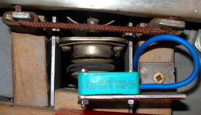
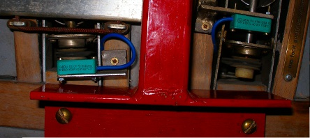 The placement
of the sensors can be seen in the pictures. The sensors are mounted with M2.5
bolts and nuts.
The placement
of the sensors can be seen in the pictures. The sensors are mounted with M2.5
bolts and nuts.
14.11.2010: Physical design... trying to make space for the new hardware...
19.11.2010: New pic controller board breadboarded. Two controllers, 18F2520
are used.
20.11.2010: Yellow LED strip mounted behind the frontal resonators. Two Nanotech
motor controllers mounted. Breadboard circuit with two PIC microcontrollers
finalized. Start coding for the firmware. Vibi webpage edited according to the
new implementation and hardware. Old version saved as Vibi_2005.html.
21.11.2010: Wiring of all new hardware on the Vibi carrier plate. Further coding
on the firmware using MPLAB and the Proton+ compiler. There are two source code
versions, one Vibi_MotKro.asm and the other Vibi_MotDia.asm, since both PIC's
listen to different controllers.
23.11.2010: Firmware source code changed such that we can use a single source
code file for both PIC's: Vibi_Motors.asm, making use of metacompiler commands.
24.11.2010: Version 1.0 flashed and tested. Some minor bugs need to be killed.
The control range for the motor speed in a substantial improvement over the
previous version. The positioning code seems to work pretty well as well. We
have to improve the firmware such as to take into account the small offset caused
by the eccentric placement of the sensor on the diatonic note row.
25.11.2010: Test and evaluation session for the new firmware. White light (note
123) added, using three 3 W Lumileds. Existing lights made controllable.Version
1.1 firmware flashed: with offset compensation for the diatonic sensor. Frontlite
still to be mounted. For debug and fine tuning purposes, we implemented controller
32 (accelleration slope), controller 70 (callibrate command) and controller
71: offset value for the diatonic sensor. The controllers should not be used
by users.
26.11.2010: Front light mounted: again three 3W LumiLeds. Further firmware debug
on controller 7 implementation. Version 1.2 now.
27.11.2010: Firmware version 1.5, motor speed much increased now. The accelleration
code in the firmware is crucial now since the motor will not start up on high
speeds otherwize.
28.11.2010: Test code added in GMT for development controllers 71, 72, 32, 70.
Firmware version 1.6 flashed in both PIC's. Highest (fake) resonator tube sawn
away for better access to the microcontrollers. Actually, all resonator tubes
can be shortened quite a bit as most of their length is non-functional, a disgusting
feature of all vibraphones it seems... PIC code seems to work nicely now, but
calibration every so often may be required for reliable positioning with controller
7. Making the valves rotate will always readjust the motor position as position
is reset everytime the valves pass the sensors. Awaiting feedback from users
now... Repair of one of the damper solenoids still to be done.
29.11.2010: Firmware improved to take into account the death traject wherein
the sensor is triggered. Now version 2.0.
02.12..2010: Backside lights replaced with 2 x 3W red LED spotlites
17.04.2013: Two metal strips added to prevent the resonators from jumping out
during transportation.
20.04.2013: <Vibi> survived the trip to Glasgow very well! We expect it
back in Ghent on monday 22nd of april.
23.04.2013: Vibi returned in perfect shape from Glasgow.
05.09.2013: Problems when attempting to send RS485 midi to Vibi's input port. Similar problem as occured with <Piperola>. Replacement of the 4N27 or CNY27 optocoupler with a 6N317 was the cure. The input port is now compatible with standard midi and differential RS485.
01.08.2017: <Vibi> taken on the road to Liepaja (Letland).
09.08.2017: <Vibi> returned safely from Liepaja, a 4000 km trip on rough
roads. As quite some of the nylon caps on the beaters were found to be worn
out, we replaced all caps on all solenoids. The last replacement was in 2010...
22.11.2017: <Vibi> joined the party at euRobotics in Brussels. Found o.k.
on return.
30.07.2019: <Vibi> returned safely from Tomorrowland. The knot in the
rope holding the bars got loose. That was an easy repair...
14.09.2023: <Vibi> on the road to the Deutsche Oper Berlin.
02.10.2023: <Vibi> returned from the trip to Berlin. All tests passed.
30.10.2023: Beater for note 61 burned out... probably as a result of playing
an almost terrorist file by S.Braadt... Maybe we should consider a complete
redesign of the hardware.
06.11.2023: Voor een re-design kunnen we voor de beaters volstaan met 2 pulse-only
boards gebruik makend van de 18F4820 chip, maar voor de dempers kunnen we beter
pulse-hold boards gebruiken: 3 boards zoals gebruikt voor <Spiro> volstaan
voor 42 noten, terwijl we slechts 37 noten te bedienen hebben. In de midi-implementatie
moeten we dan wel de besturing van de demper-hold tijd mogelijk maken. Kunnen
de bestaande voedingen echter de nodige stroom leveren om alle dempers tegelijkertijd
te bekrachtigen?
08.11.2023: Alles goed en wel beschouwd, kunnen we ook overwegen een geheel
nieuwe robot vibrafoon te ontwerpen. De dempers kunnen we dan bovenop de klankstaven
monteren. Een Yamaha model dat in aanmerking komt zou de YV2030MS kunnen zijn.
Dit type heeft de standaard vibrafoon tessituur: F,52 - f,89. Bij Thomann kost
die 3.498 Euro. De totale kost aan onderdelen alleen voor zo'n Vibi2 begroten
we op minstens zo'n 9.500 Euro. Een goedkope Bergerault kunnen we ook overwegen,
want die kost niet veel meer: 3.980 Euro. Inmiddels toch maar de tubular solenoid
voor noot 61 (do#) vervangen. Alles werkt weer naar behoren...
15.04.2024: Alle kunststof kapjes op de kloppers vervangen door nieuwe exemplaren.
De oude bleken hier en daar doorgeklopt te zijn en dus versleten.
13.09.2024: Na een stroompanne in de tetraeder bleek enkele uren na het opnieuw
onder stroom zetten van het hele robotorkest, <Vibi> verdacht gedrag te
vertonen: bij ctrl.66 on, schakelden enkele kloppermagneten aan... Bij het spelen
van de Fibonaci sektie uit mijn 'Proeven van Wiskunst' kwam er een grote rookpluim
uit het instrument opstijgen... Werk aan de winkel dus.
14.09.2024: Solenoids voor noten 62,63,64 evenals de demper-solenoide voor noot
82 vervangen. Voor het wegnemen en vervangen van dempermagneten is wel heel
wat demonteerwerk nodig... Mosfets voor demper 82, klopper 62,63,64 vervangen.
Allemaal IRL640. Op demperboard 1 (noten 72 tot 83) alle 74HCT14 chips vervangen.
Weidmueller 5V power supply konnektor op board 1 vervangen (was afgebroken bij
een vorig euvel). Eerste test na al deze herstellingen: noot 83 blijkt het nog
niet te doen. De solenoide blijkt nochtans intakt, DC weerstand 19 Ohm...
15.09.2024: Verder herstelwerk aan <Vibi>. Noot 83 werkt maar het velo-bereik
is slechts de helft van dat der overige noten. Spoel toch te heet geworden waardoor
het trajekt kleiner is geworden of de glijweerstand te groot? Spoel helemaal
vervangen. <Vibi> lijkt weer helemaal in orde. Meteen ook de sensoren
voor het vibrato mechanisme opnieuw afgeregeld.
2024-09-15 by Godfried-Willem Raes