|
Robotic Spinet Research project on the development of new tools for musical expression at the University College Ghent School of Arts
|
|
<Spiro>
an automated spinet dr.Godfried-Willem RAES 2011 |
|
Robotic Spinet Research project on the development of new tools for musical expression at the University College Ghent School of Arts
|
|
<Spiro>
an automated spinet dr.Godfried-Willem RAES 2011 |
<Spiro>
Particularly in performances related to ancient music, our regular collaborators - Xavier Verhelst and Sebastian Bradt - felt the need for a plucked string instrument such as a harpsichord. Since harpsichord making is not really what our workshop is equipped for, we started looking for specialized instrument builders in order to have them make an instrument without a keyboard so that we could undertake the automation efficiently. Of course we could have started from a complete instrument, more or less copying the design of the Vorsetzer we made for the grand piano. However, early experiments demonstrated clearly that the intermediate action of the keys added unnecessary noises and that directly pushing the jacks in a vertical plane was a better way to go. Looking around into the many possibilities, we decided to go for a rather small instrument: the spinet. This decision was taken because of the lack of space we were experiencing within the complete robot orchestra, now already composed of 48 robots. Therefore a large harpsichord was to be avoided. A virginal would also have been a possibility, but we did not like it very much because of its uninspiring rectangular shape. Thus our search lead us to Walter Maene, a retired instrument builder - Chris Maene's older brother, by the way - who had a spinet almost ready to meet our demand. This instrument formed the basis of the <Spiro> robot.
After taking the instrument apart and removing the jacks and keyboard, it came out that our initial idea of pushing the jacks directly with 56 solenoids was not really workable as the undersides of the jacks had been cut and shaped individually to fit the keys, in order to avoid keys striking more than one jack at the time. On the picture the complete series of jacks removed from the instrument can be seen:
The triangular pattern of the jack arrangement (clearly visible in the black area - the jack guides - on the picture) was clearly the reason that individual shaping was required.
This arrangement, though historically correct, has some implications with regard to the key force required: even numbered notes need a slightly greater force than the odd numbered ones. Of course we could have designed an intermediate mechanism to make inline striking of the jacks possible but after a little drawing it was clear that such a mechanism would end up with a striking resemblance to a keyboard... So we went on experimenting with the original keyboard itself. Although actually an afterthought, we also realized that the tuning of the instrument without a keyboard could become quite cumbersome, as it would dictate the use of a controlling computer with a suitable user interface. Tuning being one of the very periodic nuisances intrinsic to such stringed instruments. Measurement with the keyboard in place taught us that the required striking force for the keys was in the order of 0.8 Newton. The trajectory for the plunger movement required was less than 10 mm. The use of Ledex tubular solenoids in the 0.5" x 1" form factor came into sight. These are the essential specs, taken from the Ledex data sheet:
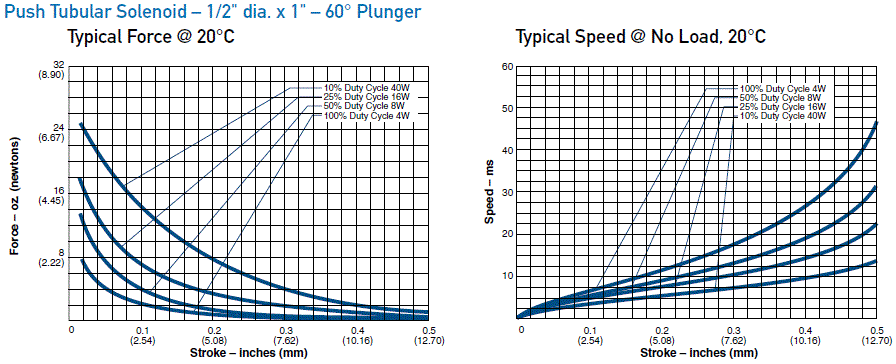
We decided to select type 195203-234 from the catalogue. The operational voltage for 100% duty cycle operation is specified at 12.2V, climbing to 39V for a 10% duty cycle. For a harpsichord it is mandatory that the jacks are lifted up very fast and with some force, much higher than the force required to keep the jacks up after plucking the string. Even though velocity sensitivity in harpsichords is no more than minimal, this dictates the application of a pulse-hold system for controlling the solenoids.
60 degree plungers were selected first of all because maximum holding force was not an issue here and also because these plungers have a much smoother movement characteristic than flat types. As an equally important bonus, we also get much quieter operation.
Calculation of the power supply requirements was quite straightforward: to cope with situations where all 56 keys are pressed down, we need a 12V power supply capable of delivering 18 amps of current. If we feed the velocity pulse voltage from 24V (leading to 36V over the solenoids during the pulse), and we know that under the MIDI protocol, note-on commands can fly in at a maximum rate of 1ms per command with a maximum pulse duration of 10ms, we can derive that a maximum of 10 pulses can coincide. Therefore the 24V power supply should have a current capacity of 6.5A.
Of particular concern in this design was the avoidance of mechanical noises from the action. Therefore we decided to provide all plungers in the solenoids with a 6 mm nylon ball that pushes the keys upwards.
The wood of the keys was covered with a layer of very thin felt at the place of activation, damping any bounce-back noises. Of course we did not neglect the fallback profile, with a thick layer of felt on the underside of the solenoids. The spacing between this profile and the solenoid carrier determines the movement trajectory of the plungers and has to be carefully adjusted in conjunction with the velocity scales implemented in the microcontroller firmware.
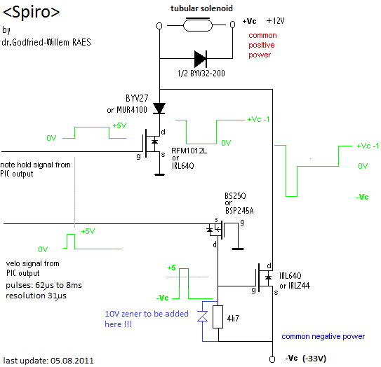
The electronic hardware does not offer anything new beyond what we developed for earlier automation projects such as the player piano, (<Qt>) the quartertone organ and <Bomi>, the woodpipe organ, to name just a few that use this technology. The microcontroller boards make use of the Microchip 18F4620 PIC processor, each board controlling 14 solenoids. Thus the entire spinet makes use of no more than four boards ( 4 x 14 = 56). The principle of operation for the implementation of velocity sensitivity is:
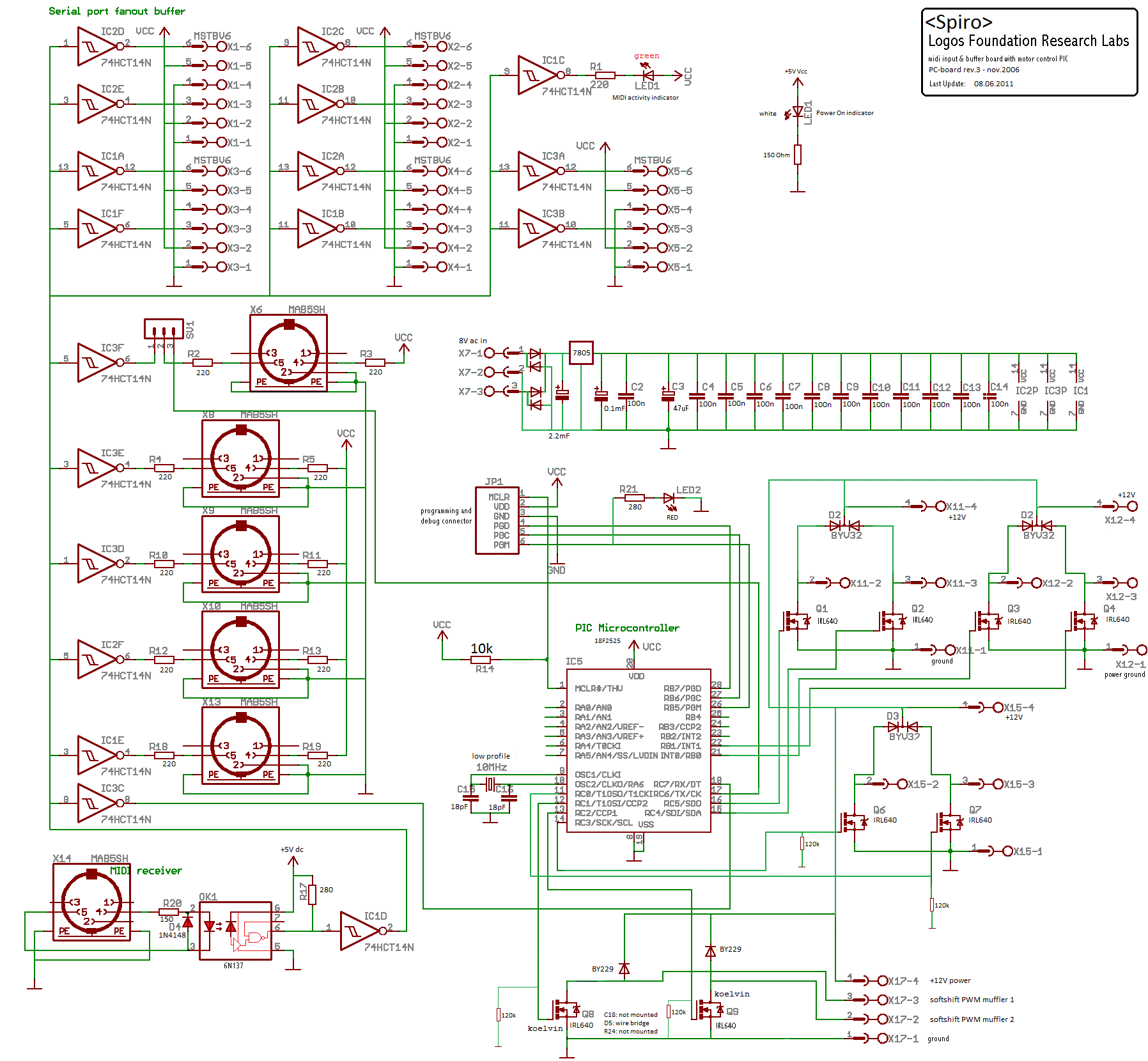
An extra microprocessor board (using a 18F2525 chip) takes care of midi-parsing as well as a few extras such as lights and a muffler mechanism, added to create a lute-like sound.
The muffler consists of a felt-covered piece of wood that can be pushed against the strings under the action of two softshift solenoids. We had the choice of either placing it close to the bridge or close to the tuning pegs. Since the curvature of the bridge would entail a complicated and fragile mechanical construction, we opted for placing the mechanism at the peg side and mounted it on the bar blocking the jacks from above. A particular difficulty in this design was to make the mechanism such that its height fits the space between the soundboard and lid. Hence small softshift solenoids were called for.
Spiro played its first automated scales on July 16th 2011. It joined the robot orchestra in August 2011. A word of warning to our users: although there are no limitations on the repetition speed of notes, using high repetition speeds can be detrimental to the jacks and the plectra are likely to break. This is a general characteristic of all harpsichord-like instruments, not a weakness of our design. In manual playing however, repetition speed is limited by the motor capabilities of human fingers. In an automated design, such capabilities far exceed human possibilities.
Although the implementation of touch sensitivity in this robot may seem dispensible, it came out after regulating the mechanism that it is essential to the implementation of lookup tables. We could not do without these for the spread in required push force is very different from key to key. Moreover, every time quills are replaced or reshaped, the lookup tables need to be updated accordingly. No two plectrums are really identical in a historical harpsichord like this one. With our look-up tables, using the instrument becomes easy: just select the required lookup with a program change command (122-127 is the range used) and in the music use a constant low value (10) for the velocities. The lookup in use under program number 122 is made such that with velocity 1 all keys ought to respond. Since there is temporal spread in the speach of the mechanism, somewhat higher values should be applied in practice.
dr.Godfried-Willem Raes
Midi Mapping and implementation:
Midi channel: 4 (0-15)
Note Off: Implemented for all notes in the range. Release byte is disregarded.
Equivalent to note-on with zero velocity.
Note On: Implemented for all notes in the range. Velo-byte is used for the stroke strength, but has only a very slight effect, as normal for harpsichords. With velo =1, under program change 0, the minimum pulsewidth of 63 microseconds is applied.
Controllers 28 and 29: Muffler controllers, Controller 28 steers the bass side, 29 the treble side. At value zero, the muffler mechanism is fully released from the strings. In-between positions are possible, as a soft-shift solenoid is used here.
Controller 66: Robot on/off switch.
Controller 123: All notes off, including the lights and the muffler.
Program Change: values 122-127 are implemented. By default, program 122 should be selected. This program is meant to be used in combination with velocity values of 10. Program change with value 0 should only be used for research, allignment and measurement and is to be considered a reserved value.
Lights:
Sys-Ex is implemented to allow for the use of different velocity scaling lookup tables, used for special effects. To select a different lookup table, a program change command is required. The range 122-127 is reserved for these programmable lookup tables. Program change with value 0 resets to the cold boot and default condition.
Technical specifications:
Collaborators on the construction of this robot:
Music composed for <Spiro>:
Pictures taken during construction in our workshop:
| Back to Main Logos page:index.html | To Godfried-Willem Raes personal home page... | To Instrument catalogue |  |
<Spiro>
Een nederlandse tekst is niet beschikbaar.
Robody foto:
Construction & Research Diary:

 Not yet done!
To do:
Conclusive remarks and criticism:
If ever we would do an automated harpsichord instrument again, following changes as compared to the <Spiro> project would apply:
1.- Start from (or build) a harpsichord were the jacks are inline. A modern harpsichord (Neupert for instance) seems more appropriate than a historical copy.
2.- Ommit the keyboard and push the jacks directly. If the keyboard needs to be kept in place, construct it such that it forms a complete unit with the solenoid assembly. Also, change the keyboard such as to have the keys rotate around a pivoting point. This would prevent the trouble we had with keys being lifted up by the force of the solenoids instead of pivoting on their center points. As an alternative to this, it could also be considered to drill 5 mm holes in the keys to let through the solenoid anchors. In such a design the keys would not move when playing automatically. Disassembly would become quite cumbersome though.
3.- Provide many more regulating screws for the mechanism.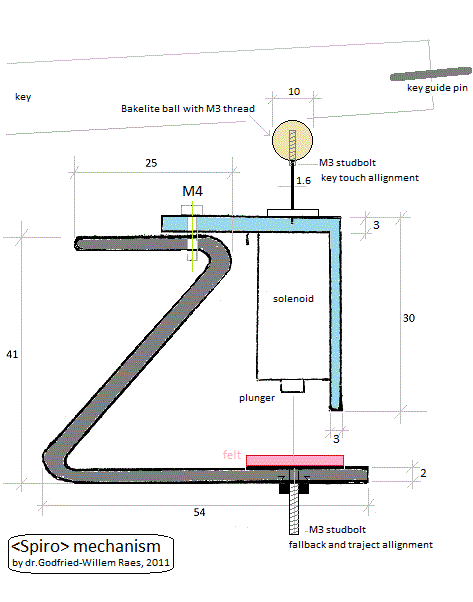 Fallback allignment screws would have made the spiro job a lot easier. As it
is now, all allignment is done by adding strokes of felt...
4.- Here is a principle drawing for the mechanism with feedthrough the keys:

5.- Correct the bug in the pulse-velo boards: a 10V zerner diode across the 4k7 resistor is required!
Note: May 2021 we obtained another spinet, made by Sperrhake, Passau, from
the legacy of an uncle who died from Covid19. We are considering to turn it
into an automate as we did with <Spiro>, but now taking into account the
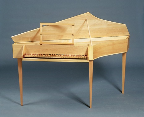
improvements mentioned on this webpage. Here is a picture of the original instrument:
 This is the ambitus:
  We finished this project, baptized <Sper>, in 2024. Here
is it's webpage.
| (Terug) naar logos-projekten: | Terug naar Logos' index-pagina: | Naar Godfried-Willem Raes personal homepage... | Naar katalogus instrumenten |  |
M&M orkest |
Last update: 2024-08-04 by Godfried-Willem Raes
The following information is not intended for the general public nor for composers wanting to make use of our <Spiro> robot, but is essential for maintenance and servicing of the robot by our collaborators. It also might be useful for people that want to undertake similar research or building projects. Feedback is always most welcomed.
Technical drawings, specs and data sheets:
Disassembly instructions:
If for any reason, the mechanism needs to be accessed, the spinet can be removed from the robotic base by loosening and removing the three M10 bolts (inbus hex) near to the legs. Make sure the instrument is in a horizontal position. Disconnect the Weidmueller connector for the muffler mechanism. Now lift up the spinet vertically from the base and put it on a table. Do not first remove the jacks and the keyboard for this operation. Note that if the keyboard needs to be moved or taken out, all jacks have to be removed first! In reassembling, place the spinet with the keyboard in place and well aligned carefully over the robotic base such that it matches the mounting holes perfectly. Do not tighten the bolts any faster than needed to hold both parts together. Do not attempt to disassemble the instrument for transportation. The only parts that could be taken off are the wheels. An short angled inbus key M12 is required.
If strings need to be replaced, always remove the upper jack bar and the muffler mechanism. Only the jack corresponding to the string to be replaced should be removed.
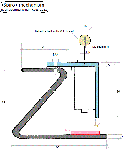
The traject of the keys can be regulated using the two sunken bolts (left and right) in the wood of the spinet's underplate. The solenoid assembly has to be adjusted with the M6 threads such that the nylon balls on the plungers just touch the felt glued on the underside of the keys. Individual allignment of the solenoids is performed using the M3 threaded studs and the balls mounted on the plungers.
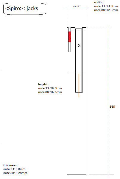
Jacks:
Boards and components:
Midi-hub board: (scaled 50%, right click picture and save to view in full scale)
Soft shift solenoids used for the muffler mechanism: Saia Burgess (Lucas Ledex) type 198090-001, cage 81840.
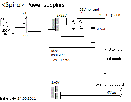
Power supplies:
Solenoid carrier chassis cross section drawing:
Wiring tables for the three PIC 18F4620 controller boards:
Board 1:
| board output | connector pin | mapping | remarks | PIC pin |
| 1 | 2 | note 33 | pulse/hold | 4,3 |
| 2 | 3 | note 34 | pulse/hold | 2,5 |
| 3 | 4 | note 35 | pulse/hold | 6,7 |
| 4 | 5 | note 36 | pulse/hold | 8,9 |
| 5 | 7 |
note 37 |
pulse/hold | 10, 37 |
| 6 | 8 |
note 38 |
pulse/hold | 36, 35 |
| 7 | 9 | note 39 | pulse/hold | 34, 33 |
| 8 | 10 | note 40 | pulse/hold | 30, 29 |
| 9 | 12 | note 41 | pulse/hold | 28, 27 |
| 10 | 13 | note 42 | pulse/hold | 24, 23 |
| 11 | 14 | note 43 | pulse/hold | 22, 21 |
| 12 | 15 | note 44 | pulse/hold | 15, 16 |
| 13 | 17 | note 45 | pulse/hold | 17, 18 |
| 14 | 18 | note 46 | pulse/hold | 19, 20 |
Board 2:
| board output | connector pin | mapping | remarks | PIC pins |
| 1 | 2 | note 47 | pulse/hold | 4, 3 |
| 2 | 3 | note 48 | pulse/hold | 2, 5 |
| 3 | 4 | note 49 | pulse/hold | 6, 7 |
| 4 | 5 | note 50 | pulse/hold | 8, 9 |
| 5 | 7 | note 51 | pulse/hold | 10, 37 |
| 6 | 8 | note 52 | pulse/hold | 36, 35 |
| 7 | 9 | note 53 | pulse/hold | 34, 33 |
| 8 | 10 | note 54 | pulse/hold | 30, 29 |
| 9 | 12 | note 55 | pulse/hold | 28, 27 |
| 10 | 13 | note 56 | pulse/hold | 24, 23 |
| 11 | 14 | note 57 | pulse/hold | 22, 21 |
| 12 | 15 | note 58 | pulse/hold | 15, 16 |
| 13 | 17 | note 59 | pulse/hold | 17, 18 |
| 14 | 18 | note 60 | pulse/hold | 19, 20 |
Board 3:
| board output | connector pin | mapping | remarks | PIC pins |
| 1 | 2 | note 61 | pulse/hold | 4, 3 |
| 2 | 3 | note 62 | pulse/hold | 2, 5 |
| 3 | 4 | note 63 | pulse/hold | 6, 7 |
| 4 | 5 | note 64 | pulse/hold | 8, 9 |
| 5 | 7 | note 65 | pulse/hold | 10, 37 |
| 6 | 8 | note 66 | pulse/hold | 36, 35 |
| 7 | 9 | note 67 | pulse/hold | 34, 33 |
| 8 | 10 | note 68 | pulse/hold | 30, 29 |
| 9 | 12 | note 69 | pulse/hold | 28, 27 |
| 10 | 13 | note 70 | pulse/hold | 24, 23 |
| 11 | 14 | note 71 | pulse/hold | 22, 21 |
| 12 | 15 | note 72 | pulse/hold | 15, 16 |
| 13 | 17 | note 73 | pulse/hold | 17, 18 |
| 14 | 18 | note 74 | pulse/hold | 19, 20 |
Board 4:
| board output | connector pin | mapping | remarks | PIC pins |
| 1 | 2 | note 75 | pulse/hold | 4, 3 |
| 2 | 3 | note 76 | pulse/hold | 2, 5 |
| 3 | 4 | note 77 | pulse/hold | 6, 7 |
| 4 | 5 | note 78 | pulse/hold | 8, 9 |
| 5 | 7 | note 79 | pulse/hold | 10, 37 |
| 6 | 8 | note 80 | pulse/hold | 36, 35 |
| 7 | 9 | note 81 | pulse/hold | 34, 33 |
| 8 | 10 | note 82 | pulse/hold | 30, 29 |
| 9 | 12 | note 83 | pulse/hold | 28, 27 |
| 10 | 13 | note 84 | pulse/hold | 24, 23 |
| 11 | 14 | note 85 | pulse/hold | 22, 21 |
| 12 | 15 | note 86 | pulse/hold | 15, 16 |
| 13 | 17 | note 87 | pulse/hold | 17, 18 |
| 14 | 18 | note 88 | pulse/hold | 19, 20 |
References:
NEUPERT, Hanns "Harpsichord Manual" (2nd edition, translated by F.E.Kirby), Baerenreiter, Kassel, 1968
RAES, Godfried-Willem, "Expression control in musical automates", 1977/2013,
RIPIN, Edwin M (ed.) ., "Keyboard Instruments. Studies in Keyboard organology 1500-1800", ed. Dover Publications Inc., New York, 1977, ISBN 0-486-23363-4
ROSSING, Thomas.D (editor), "The Science of String Instruments" , ed: Springer NY, Stanford CCRMA, 2010 ISBN 978-1-4419-7109-8