|
<Flex>
|
|
Godfried-Willem
RAES
2002 /
2016
|
Robot:
'Flex'
Of all musical instruments, the singing saw very likely should be considered
one of the most stubborn. It is very difficult to master well, and even mastered,
it remains quite unreliable. Automating such a sound source constituted a real
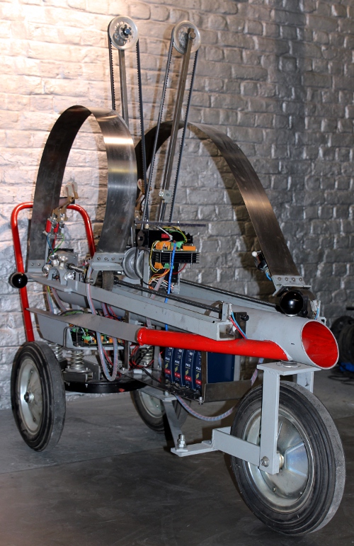
challenge. Our musical robot <Flex> consists of an assembly of two singing
saw or flexatone like soundsources: two blades of hardened stainless steel either
bowed by belt driven bow mechanisms or struck by beaters. For the latter we
provided two possibilities: solenoid and/or motor driven beaters and bend by
a system of heavy duty stepping motors. In this respect it may be considered
a realization of Russolo's fifth category in noise makers (intonarumori): sound
of metals, stone etc. The lengths of the singing blades relate to each other
as Pi to e, the two most infamous irrational numbers both in physics and mathematics.
One would expect the Pi saw being lower pitched than the e saw, but that assumption
is insubstantial in this case. The lowest resonant frequencies of the saws are
extremely low and far lower than the lowest pitches we can hear. Thus the sounds
produced correspond always to very high partials and modes of vibration, very
inharmonic in nature. Bending the blades changes their resonant frequency and
therefore glissandi can be produced. With the bowing mechanism provided, it
constitutes a double singing saw. With the beaters, it's rather a super large
flexatone.
The building of this robot was started in 2002 and in its first version, was
controlled through a printer port on a laptop computer. Internally it made use
of some 8 Microchip PIC based Basic Stamps. Details on the original design,
which we had to abandon as printer ports on PC's became obsolete, can be found
on the archival webpage for this robot. In
2016 we undertook a complete rebuild of the robot, preserving all possibilities
of the first version and adding quite a bit more. We redesigned the electronics
completely and made use of five Microchip 18F2525 microcontrollers. All newly
added mechanical parts are made off stainless steel now.
The circuitry used is very similar to that developed
for our <Rotomoton> robot, although we used a different kind of stepping
motor (4-phase, 0.45 Ohm coil resistance, 1.2mH inductance), requiring a much
higher current of up to 4.5A per winding. Two stepping motors are used for bending
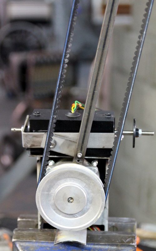
the steel blades and two more steppers for the bow motion. The bows, 70cm in
length, are mounted vertically, facing each other on the central tube of the
robot. Here we made use of V-belts with rosin on the flat outside. The belts
run over 10 cm diameter aluminum wheels. Positioning of the bows against the
blades is achieved with two bi-directional solenoids, PWM-controlled by the
bowing PIC-microprocessors. A sensor mounted on the bow arm makes precise positioning
possible. Thus bowing speed as well as bow pressure can be user controlled as
separate parameters. Since motor speed can be controlled by the software in
the range of 0.5 Hz to 5 Hz, the bowing speed ranges from 160cm/s to 1.57m/s.
Ramping is implemented on all motor functions, thus preventing stalling of the
motors.
The individual beaters for the steel blades (two beaters
on the backside of each saw blade) are driven by strong solenoids. Musical dynamics
are implemented by applying pulse width modulation techniques in the driver
circuits. However, the dynamic range is different from blade to blade and also
depends on the amount of bending applied by the stepping motors. On the front
side of the blades, we mounted small DC motors with rotating beaters. The speed
of these can be controlled.
<Flex> uses five microprocessors, all of them Microchip PIC type 18F2525.
Two processors are used for the bows, two for the trapezoidal threads and one
for the beaters and lights.
The instrument is mounted in a TIG-welded triangular structure with three large
and sturdy wheels, 40 cm in diameter each. The instrumental part is mounted
on the wheel base with springs.
Of all our robotic instruments, <Flex> may be one of the most complicated
and difficult to write music for. It is nearly impossible to write anything
meaningful without working with the robot itself. A thorough study of the midi
implementation table is absolutely mandatory.
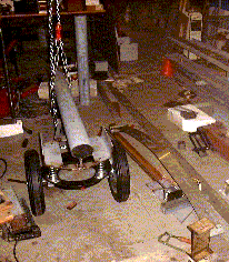
The pictures below are taken by Moniek Darge, during the first construction
in our workshop, 2002. They are arranged in chronological order such that you
can follow the process of the making visually.
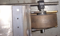
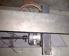
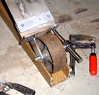
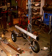

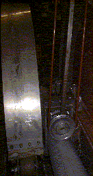
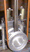
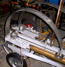
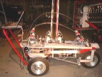
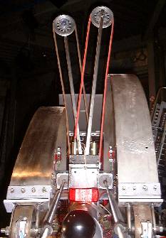
These are some pictures taken by the author during the rebuild in 2016:
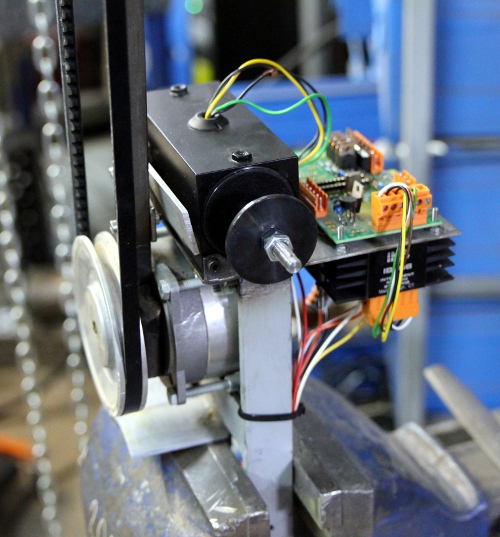
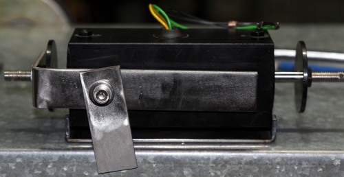

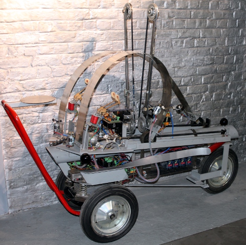
- Design & construction: Dr.Godfried-Willem Raes
- size: 600mm width, 1600mm length, 1500mm height
- weight: 135 kg
- control: MIDI input.
- Insurance value: 24.000 Euro
Midi implementation table (Version 2.0):

Flex listens to midi channel 12 (0-16) [13 if counting
1-16]
Here is the complete midi implementation table:
|
Note numbers
|
function |
velocity |
remarks
|
| NOTE ON/OFF |
|
|
|
| BENDING |
|
|
|
| 36 |
Pi-saw positioning command |
1-127 |
the velocity byte controls the speed of the motor
Movement will stop as soon as the position set with the pitchbend command
is reached. Motor speed can be further modulated using the keypressure
command.
A note-off will stop the motor unconditionally.
|
| 37 |
e-saw positioning command |
1-127 |
the velocity byte controls the speed of the motor
Movement will stop as soon as the position set with the pitchbend command
is reached. Motor speed can be further modulated using the keypressure
command.
A note-off will stop the motor unconditionally.
|
| 38 |
fully stretch the Pi saw |
1-127 |
the velocity byte controls the speed of the motor
Movement will stop as soon as the fully stretched position is reached.
This will cause a recalibration of the positioning mechanism.
A note-off will stop the motor unconditionally,
but will annihilate calibration if sent before the saw reached the end
position.
|
| 39 |
fully stretch the e saw |
1-127 |
the velocity byte controls the speed of the motor
Movement will stop as soon as the fully stretched position is reached.
This will cause a recalibration of the positioning mechanism.
A note-off will stop the motor unconditionally,
but will annihilate calibration if sent before the saw reached the end
position.
|
| 40 |
fully bend the Pi saw |
1-127 |
the velocity byte controls the speed of the motor
Movement will stop as soon as the fully inward bend position is reached.
If this happens it recalibrates the trajectory settings in the firmware.
A note-off will stop the motor unconditionally.
but will annihilate calibration if sent before the saw reached the inward
end position.
|
| 41 |
fully bend the e saw |
1-127 |
the velocity byte controls the speed of the motor
Movement will stop as soon as the fully inward bend position is reached.
If this happens it recalibrates the trajectory settings in the firmware.
A note-off will stop the motor unconditionally,
but will annihilate calibration if sent before the saw reached the inward
end position.
|
| BOWING |
BOW MOVEMENT (Motor) |
|
Ramping is implemented, to avoid stalling |
| 48 |
frontbow motor, turn clockwise |
1-127 |
velocity controls motor speed
Motor can be further modulated with the key pressure command
|
| |
frontbow motor, stop turning |
0 |
|
| 49 |
frontbow motor, turn counterclockwise |
1-127 |
velocity controls motor speed
Motor can be further modulated with the key pressure command
|
| |
frontbow motor, stop turning |
0 |
|
| 50 |
backbow motor, turn clockwise |
1-127 |
velocity controls motor speed
Motor can be further modulated with the key pressure command
|
| |
backbow, stop turning |
0 |
|
| 51 |
backbow motor, turn counterclockwise |
1-127 |
velocity controls motor speed
Motor can be further modulated with the key pressure command
|
| |
backbow, stop turning |
0 |
|
| BOWS |
BOW POSITION and PRESSURE |
|
|
| 60 |
pulse and hold frontbow to Pi-Saw |
1-127 |
the bowing force is controlled with the velo byte. After the
note on, the bow pressure can be further modulated using the key pressure
command |
| |
release pusher, return to center |
0 |
sets bow pressure on the Pi-blade to 0 |
| 61 |
pulse and hold frontbow to e-Saw |
1-127 |
the bowing force is controlled with the velo byte. After the
note on, the bow pressure can be further modulated using the key pressure
command |
| |
release pusher, return to center |
0 |
sets bow pressure on the e-blade to 0 |
| 62 |
pulse and hold backbow to Pi-Saw |
1-127 |
the bowing force is controlled with the velo byte |
| |
release pusher, return to center |
0 |
sets bow pressure on the Pi-blade to 0 |
| 63 |
pulse and hold backbow to e-Saw |
1-127 |
the bowing force is controlled with the velo byte |
| |
release pusher, return to center |
0 |
sets bow pressure on the e-blade to 0 |
| 64 |
center frontbow such that it does not touch any saw blade |
1-127 |
velobyte is irrelevant.
This command will also stop the bow motor
|
| |
|
0 |
release the holding magnet (clutch)
also stops the bow motor
|
| 65 |
center backbow such that it does not touch any saw blade |
1-127 |
velocity byte is irrelevant.
This command will also stop the bow motor
|
| |
|
0 |
release the holding magnet
also stops the bow motor
|
| BEATERS |
|
|
|
| 72 |
frontal motor beater on Pi-saw |
1-127 |
velocity byte steers motor speed |
| 73 |
motor beater on backside of Pi-saw |
1-127 |
velocity byte steers motor speed |
| 74 |
Backside beater on the Pi saw |
1-127 |
velo steers attack force |
| 75 |
Backside beater on the Pi saw |
1-127 |
velo steers attack force |
| 84 |
frontal motor beater on e-saw |
1-127 |
velocity byte steers motor speed |
| 85 |
motor beater on backside of e-saw |
1-127 |
velocity byte steers motor speed |
| 86 |
Backside beater on the e-saw |
1-127 |
velo steers attack force |
| 87 |
Backside beater on the e-saw |
1-127 |
velo steers attack force |
| LIGHTS |
|
|
key pressure is implemented to modulate
flashing speed |
| 120-123 |
backside halogen lights on the e saw |
0-127 |
the velocity byte steers the flashing speed, 0=off, 127=on
without flashing. |
| 124-127 |
backside halogen lights on the Pi saw |
0-127 |
the velocity byte steers the flashing speed, 0=off, 127=on
without flashing. |
| |
|
|
|
| KEY PRESSURE |
|
|
|
| 36 |
changes the speed of the Pi saw bending motor |
1-127 |
only applies if a note on command was given for note 36 |
| 37 |
changes the speed of the e saw bending motor |
1-127 |
only applies if a note on command was given for note 37 |
| 48 |
frontbow motor speed CW |
0-127 |
note must be on prior to sending the command |
| 49 |
frontbow motor speed CCW |
0-127 |
note must be on prior to sending the command |
| 50 |
backbow motor speed CW |
0-127 |
note must be on prior to sending the command |
| 51 |
backbow motor speed CCW |
0-127 |
note must be on prior to sending the command |
| 60 |
key pressure frontbow on the Pi-blade |
0-127 |
controls the bow pressure for the front bow
note must be on prior to sending the command
|
| 61 |
key pressure frontbow on the e-blade |
0-127 |
controls the bow pressure for the front bow
note must be on prior to sending the command
|
| 62 |
key pressure backbow on the Pi-blade |
0-127 |
controls the bow pressure for the back bow
note must be on prior to sending the command
|
| 63 |
key pressure backbow on the e-blade |
0-127 |
controls the bow pressure for the back bow
note must be on prior to sending the command
|
| 72 |
speed of rotation for the motor beater on the Pi saw |
1-127 |
|
| 73 |
speed of rotation for the back motor
beater on the Pi saw |
1-127 |
|
| 74 |
repetition rate for Pi beater backside |
0-127 |
0 disables repetition |
| 75 |
repetition rate for Pi beater backside |
0-127 |
0 disables repetition |
| 84 |
speed of rotation for the frontal motor beater on the e-saw |
1-127 |
|
| 85 |
speed of rotation for the back motor
beater on the e-saw |
1-127 |
|
| 86 |
repetition rate for e-saw beater backside |
0-127 |
0 disables repetition |
| 87 |
repetition rate for e-saw beater backside |
0-127 |
0 disables repetition |
|
CONTROLLERS
controller nr
|
|
parameter |
|
| 41 |
Attack bow force on direction changes |
0-127 |
Implemented for firmware development
default = 112
|
| 42 |
Hysteresis control |
0-127 |
for bow centering PID regulation
Implemented for firmware development only
default = 56
|
| 43 |
Attack pulse duration for the bow movement |
1-127 |
default = 127 |
| 44 |
Ramping speed for the bow motors |
1-127 |
default = 64 |
| 45 |
sets the destination for the pitch bend command |
|
0-63 = pitchbend commands apply to Pi-blade
64-127 = pitchbend commands apply to e-blade
|
| 46 |
Ramping speed for the bending motors |
1-127 |
default = 64 |
| 66 |
Power on/off switch |
0 or >0 |
Power off resets all controllers and repetition rates. It
preserves the calibration. |
| 123 |
All notes off |
anything |
stops all activity, does not reset controllers nor repetition
rates. |
| Program change |
not implemented |
|
|
| PITCH BEND |
sets the bending position of either the Pi or the e blade,
depending on ctrl #45 |
0-234
(msb=0 or 1, lsb=0 to 127)
|
0 = fully stretched. (Lowest pitch)
8 bits used. MSB-LSB format, to comply with the midi standard.
One unit corresponds to a full rotation of the thread. This equals a
3 mm displacement.
msb=1 and lsb=107 bring the saw blades to the fully bend inward position.
|
Remarks:
- Following note couples are mutually exclusive: [48,49], [50,51], [60,61],
[62,63].
- Key pressure commands will only work on the bows if the corresponding note
is turned on. The same condition applies to the speed of the bending motors.
The speed can only be controlled during the time the motor is moving.
- On cold boot, the robot will always bring the saws to the fully stretched
position as soon as controller 66 goes high for the first time. Never touch
the sensors when power is on, as this will invalidate the calibration, making
position control impossible.
- Fast switching of the power on/off controller should be avoided!
Nederlands:
Robot: <Flex> 
<Flex> behoort tot de kategorie robots met niet precies bepaalbare, of
-preciezer gesteld- voorspelbare, toonhoogte. Het klankopwekkingsprincipe is
hetzelfde als dat wat ten grondslag ligt aan zowel de zingende zaag als aan
de flexatone: gebogen veerstalen platen die gestreken (zingende zaag) of aangeslagen
(flexatone) worden, waarbij de toonhoogte afhangt van de mate van buiging van
de platen. Roestvast staal of veerstaal is hiervoor, vanwege de grote hardheid,
het meest geschikte materiaal. Net zoals <ThunderWood>
kan ook deze robot gezien worden als een realisatie van een geluidskategorie
in de reeks intonarumori van Luigi Russolo, met name in dit geval de 5e groep
(metaalgeluiden).
De beide uit roestvast staal gemaakte klankbladen waarmee <Flex> is opgebouwd,
kunnen zowel worden aangeslagen als gestreken. Daartoe wordt elk zaagblad uitgerust
met niet minder dan 4 elektromagnetische kloppers en van een motorgestuurd aanstrijkmechanisme.
De strijksnelheid zowel als de ritmiek kunnen perfekt worden gestuurd. Voor
de strijkstokken gebruikten we stappenmotoren voorzien van een loopwiel met
een diameter van 100 mm. De motorsnelheid kan gestuurd worden tussen 0.5 en
5 omwentelingen per sekonde. Dat brengt een regelbare boogsnelheid met zich
van 0.16m/s tot 1.57 m/s. De beweging van de boog wordt gestuurd met per boog
een enkele zware bidirektionele elektromagneet. Hierdoor kan elke boog zowel
tegen het Pi- als tegen het E-blad worden gedrukt en gestreken. Worden beide
magneethelften geaktiveerd, dan keert de boog terug naar de middenstand en raakt
hij geen van beide bladveren. Sensoren gemonteerd op de armen van de boog maken
een nauwkeurige regeling mogelijk. Aangezien we twee strijkstokmechanismen voorzagen,
is het perfekt mogelijk beide bladen tegelijkertijd aan te strijken, maar ook,
om eenzelfde zaagblad met twee bogen tegelijkertijd te strijken, wat vaak de
produktie van multiphonics voor gevolg heeft, ook al is het resultaat in dit
geval niet helemaal voorspelbaar noch betrouwbaar.
De voedingen voor flex zijn erg uitgebreid, vooral vanwege de grote vermogens
nodig voor de aansturing van de stappenmotoren.
Bouwdagboek (vanaf 2016 in het engels):
Omdat ons vaak wordt gevraagd hoeveel werk en tijd kruipt in,
en nodig is voor, het bouwen van een muzikale robot, hebben we -zoals we het
eerder deden voor <Belly>, ook voor <Flex>
een beknopt bouwdagboek bijgehouden. De ervaring met Belly leerde ons bovendien
dat het bijhouden van zo'n dagboek ook erg nuttig is wanneer naderhand bepaalde
details moeten worden bijgesteld of onderdelen vervangen.
- 08-13 april 2002: eerste ideen en konkrete tekeningen
- 12-16 mei 2002: klank experimenten met inox platen en veren
- 25.07.2002: PC board voor stappenmotoren bestukt en gesoldeerd.
- 13.08.2002: BS2 programma voor stappenmotoren ontworpen en getest
- 15.08.2002: Laswerk wielbasis, achterwiel op kogelkrans. Versnijdingen staal.
- 16.08.2002: aflassen achterwiel met TIG toorts.
- 17.08.2002: ontwerp en snijden vork voorwiel
- 18.08.2002: aflassen voorwiel en vork.
- 19.08.2002: uittekenen basischassis. Bestelling trapezium schroefdraden
bij MEA.
- 20.08.2002: draagchassis uitgezaagd in 110 mm dikwandige buis. Vering op
voorwiel met schotelveren. Test met sporing stalen wiel in U profielen 40x50.
Plaatsing stappenmotoren uitgetekend.
- 21.08.2002: vering chassis ontworpen. Uitsnijdingen 100x100x5 profielen
onder 120 graden. Het achterdeel krijgt 4 spiraalveren, terwijl het voorwiel
met schotelveren (gat 22 mm) wordt uitgerust.
- 22.08.2002: Bevestiginsplaten stappenmotoren gelast.
- 23.08.2002: inkopen MEA. Basischassis elektronika ineengelast.
- 24.08.2002: berekeningen motoren en hamers
- 25.08.2002: centrale buis chassis onder verstek uitgezaagd. Schuine steunen
gesneden en aangelast. Voorlopige montage met spanschroeven. Test principiele
werking
- 29.08.2002: software support toegevoegd aan de GMT library g_h.dll
- 29.08.2002: montagetakel gemonteerd in atelier. Installatie pneumatische
boor.

- 30.08.2002: ontwerp askoppeling trapeziumdraad naar stappenmotor as.
- 07.09.2002: levering trapeziumdraad moeren (12mm). Uitsnijden basisplaten
stappenmotoren en inox eindblokken. Lassen askoppelingen.

- 08.09.2002: wielrails aan montageplaat stappenmotoren gelast. Inklemstukken
inox bladen geboord en gelast. De lengteverhouding van de inox bladen wordt
bepaald op e/pi (1300mm / 1502mm). De stappenmotoren kunnen nu met gemonteerde
inox bladen getest worden.
- 09.09.2002: eerste versie stamp programma voor sturing stappenmotoren.
- 10.09.2002: tests met de gemonteerde zaagbladen en de stappenmotoren. Optimalisatie
van de Stamp-kode. GMT-testroutines toegevoegd aan de module g_robots. De
stappenmotoren halen nu reeds een toerental van 300 rpm of 5 omwentelingen
per sekonde. Daarboven gaan de motoren slippen.
- 11.09.2002: serie halogeenlampen gemonteerd in de sturing van de stappenmotoren.
(12Volt/ 35 Watt lampen). De lampen worden gebruikt als spanningsgestuurde
weerstanden.
- 12.09.2002: microswitch sensoren berekend en uitgetekend voor positiebepaling
van de zaagbladen.
- 13.09.2002: inboren bedradingsgaten, vastzetten zaagbladen met inox inbusbouten.
- 14.09.2002: research naar bruikbare boogmaterialen en konstruktiewijzen.
Hard technisch silicone ofwel nylon blijken bruikbaar. Latex, Buna, rubber,
Neopreen etc... volstrekt niet.
- 15.09.2002: TIG laswerk T-steunen voor eindsensoren, halve oktogonen voor
de halogeenlampen, plaatjes beginsensoren. Kodering voor sensoren opgenomen
in de firmware voor de BS2's op de stappenmotoren print.
- 16.09.2002: Nieuwe printen ontworpen voor 5Volt logic power supply en voor
stappenmotorbesturingen met BS2 Stamp PIC controllers. Onderzoek naar leverbaarheid
standaard snaarwielen diameter 80 tot 100mm voor realisatie automatische strijkstokken.
- 17.09.2002: Motor steunplaten voor strijkmotoren gesneden, geboord en gemonteerd.
Steunen flex-geleiders voorwiel uit 5/4" buis gezaagd en rondgevijld.
- 18.09.2002: Kogellagers gemonteerd in beugels voor strijkstokken. Beugels
gelast aan lagerhouders. De poelies zijn inmiddels besteld...
- 24.09.2002: PC boards voor voedingen geleverd. Proeflassen aandrijfriemen
met speciale klemtang en lasbout.
- 25.09.2002: Triple 5V power supply gebouwd. Voeding voor de stappenmotoren
ontworpen. (2x 12V / 12,5A)
- 27.09.2002: TIG laswerk onderstel flex: kruisdissel. Oplassen 5/4"
buizen onder 30 graden aan neus robot.
- 28.09.2002: Laswerk onderstel en montage beugels pi en e bladen op achterkant
met 16mm bouten. Schilderwerk zinkoxide coating onderkant. Montage halogeenlampen
op halve boog zaagblad stappenmotoren. Besturing handgreep montagebeugel opgelast
aan onderstel in 3/4" buis. Geplooid met plooipomp onder 120 graden.
De printplaten kunnen nu vertikaal worden gemonteerd onder de stappenmotoren.
- 29.09.2002: Montageplaten PC boards voor Flex opgebouwd. Rechterhersenhelft
werkt reeds: multiplexer, dual PIC controllers, netfilter, 5V power supply,
USB port. Zijkanten in bandstaal geplooid en opgelast. Vormcitaat strijkinstrumenten.
- 02.10.2002: afdraaien wielschijven voor bogen op de draaibank. Montage dubbele
kogellagers in bogen en borging wielschijven op motorassen met Locktite. De
motorassen hebben een diameter van 9.52mm en zijn voorzien van een afplatting.
Bovenwielen uitgeboord met asgat 12mm. Inox bouten M12 met ongetapt deel van
50mm toegepast als as. Packard Bell laptop gekocht voor besturing Flex. Elektronische
overzichtsschemas opnieuw getekend.
- 03.10.2002: steunen ontworpen en gelast voor boogbekrachtigingselektromagneten.
Twee elektromagneten voor elke boog. Middenstand moet worden verzekerd met
een veer. Op deze wijze kan elke boog zowel het Pi als het e-blad aanstrijken.
Levering 4-byte printen door Digit service.(Oostende)Deze printen zijn nodig
voor de besturing van de boogmotoren.
 .
Tests met aaneensmelten van de elastomeren voor het boogmateriaal.
- 04.10.2002: Montage boogmotoren op centrale ronde buis voor motoren test.
Byte board voor boogmotoren bestukt.
- 09.10.2002: levering en montage kogelknoppen en dubbelspiraalveren.
- 11.11.2002: werk aan flex terug opgenomen. Positietests voor de strijkmekanismen.
- 26.12.2002: assemblage power supply 2 x 14V/ 12A voor voeding stappenmotoren.
TIG laswerk chassis voeding. Hangbeugels vervaardigd voor deze voedingsmodule.
- 27.12.2002: bedrading blade steppers en sensoren. Test rechterhersenhelft.
BS2's run o.k. USB-ingang gemonteerd.
- 28.12.2002: Test funktioneren sensoren en sturing draadstangen. BS2 kode
versie 1.4 ge-upload.
- 29.12.2002: Assemblage velo/hold board met Intel 8254 timers.
- 30.12.2002: Linkerhersenhelft gemonteerd en bedraad. Eerste tests elektronische
hardware. Logos displayprint gemonteerd. BS2 board voor besturing boog-motoren
gemonteerd en getest. Bedradingsschema (file: SCH_flex_adresses.gif) gemaakt
voor service dokumentatie. Op de voeding voor de elektromagneten na, is alle
elektronische hardware nu klaar.
- 31.12.2002: Montage linkerhersenhelft in chassis van Flex. Verbindingen
tussen beide hersenhelften tot stand gebracht. Positionering strijkmotoren:
experimenten.
- 01.01.2003: Test boogmotoren. Voedingsspanning steppers verhoogd.
- 02.01.2003: Serieweerstanden toegevoegd in sturing boogmotoren. Negatieve
voeding gemonteerd. Eerste tests met hamertjes. De boogduwmagneten blijken
te zwak. Veren toevoegen voor nulpositie? IRL640's doorgebrand...
- 03.01.2003: 2e stamp print hersteld en opnieuw demonteerd. Bedrading pushers.
Lassen harmersteuntjes. Verjaardagsdemo...
- 04.01.2003: Printbug hersteld op hamer 2 (bleef bekrachtigd). Ontwerp harsbakje.
Kode update in DLL.
- 05.01.2003: Steuntjes gelast voor de achterhamers. Achterhamers gemonteerd
en bedraad. Nieuwe riem gemaakt voor de frontale boog. Aluminium loopwiel
gemonteerd op as. Problemen met de voeding van de boogmotoren blijven... al
6 BDX69 gesneuveld tijdens de proeven. We overwegen ook hier serie halogeen
lampen te plaatsen. 2x 50W/ 12V moet volstaan. Beter afzonderlijke voeding
gebruiken voor pushers, hamers en boogmotoren.
- 06.01.2003: demo principiele werking voor studenten. De snelheid van de
hamertjes is alleszins superieur aan die van vorige automaten. De buffering
in de gmt USB kode kan daar ook voor iets in tussen zitten.
- 07.01.2003: bouw voeding voor de beaters en de pushers (positieve spanning,
14.5V). 50Watt halogeenlampen ingekocht voor serieschakeling met de boogmotoren
ter beperking van de stroom.
- 09.01.2003: demo voor Erwin Stache.
- 10.01.2003: Boogmotoren voeding veranderd: nu gebruiken we een geschakelde
voeding afgeregeld op 14V/ 15A. Nu blijft echter geen ruimte over voor de
plaatsing van akkus...
- 11.01.2003: Plasma snijwerk in inox voor laptop houder uitgevoerd. Stuurstang
geplooid en gelast. Boogmechanisme op chassis bevestigd. Zaagunits Pi en e
gemonteerd op chassis met inox bouten. Wielen boogmotoren geperforeerd (minder
massa in de punt van de boog). Wielprofiel intern afgerond: het bestaande
V-profiel gaf teveel klemspanning op het boogmateriaal.
- 12.01.2003: Schilderwerk Moniek Darge aan Flex. Afwerking bedrading.
- 13.01.2003: Kodering manueel besturinginterface in GMT.
- 14.01.2003: Kolofaan oplossing in alkohol aangebracht op strijkstokken.
- 15.01.2003: eerste publieke demonstratie van Flex op een M&M koncert
in de Logos Tetraeder.
- 17.01.2003: eerste Midi-implementatie gekodeerd in GMT.
- 18.01.2003: verbeteringen aangebracht in de voedingen van Flex.
- 19.01.2003: Midi implementatie uitgewerkt. Toegevoegd als doc. aan deze
webpage.
- 20.01.2003: test sessie midi implementatie. Specifikatie nieuwe elektromagneten
berekend. Horizontal softshift solenoids: Ledex Softshift type 5EP, number
193015-026. Cold DC resistance 10.3 Ohm. Nominal working voltage at 100% duty
cycle: 14V (force = 8 Newton), at 50% (force = 18 Newton) , 20V, at 25% (force=
30Newton) , 28V at 10%, 44V (force= 50 Newton) . Price (no joke): 144US $
a piece...
- 21.01.2003: bestelling Ledex elektromagneten. Vertical bow pushers: Ledex
STA series push tubular solenoid type nr. 195207-228. They have a cold DC
resistance of 19.1 Ohm. The nominal working voltage, at which the coils can
be activated indefinitly long is 13.8V. At 10% duty cycle, a voltage of 44V
may be applied. (At 19.6V , 50% duty cycle; at 28V 25% duty cycle). Price:
ca. 14 US$ a piece.
- 23.01.2003: Debug-sessie midi sturing door Kristof Lauwers. Levering Ledex
softshift elektromagneten, besteld voor verbetering werking boogaandrukmechanisme.
(Type 5EP , order type number 193015-026, 156$ per stuk!)
- 25.01.2003: laswerk en montage nieuwe softshift elektromagneten. Problemen
met te gering bewegingstrajekt.
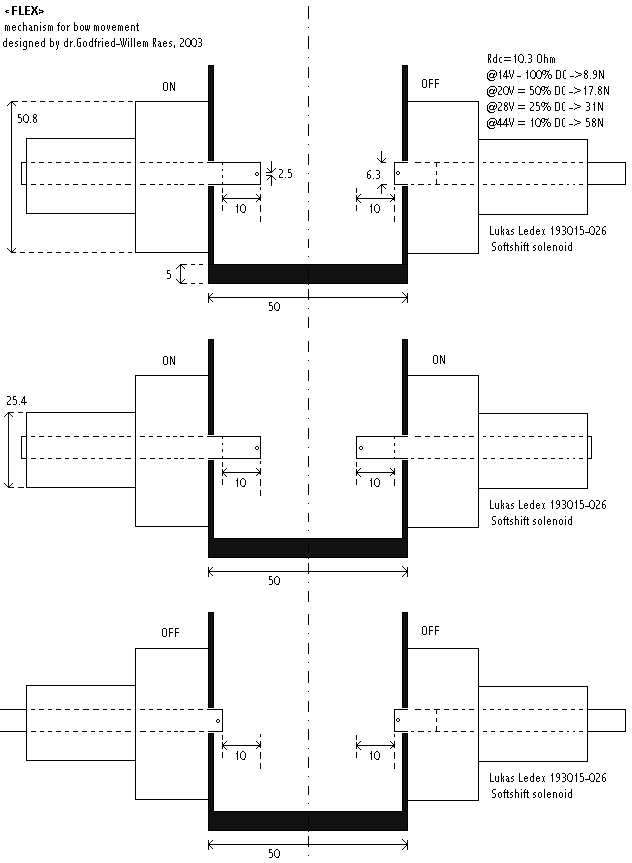
- 26.01.2003: PC board ontworpen voor 4 PIC controllers voor de PWM sturing
van de softshift magneten. Het totaal aantal processoren in Flex wordt daarmee
8 stuks.
- 27.01.2003: bestelling Digit PC. Bijwerking schakelkringen voor Flex.
- 01.02.2003: Akselleratiesensor ontworpen voor Flex, gebruik makend van ADXL202
chip van Analog devices gekoppeld aan een BS2 PIC controller.
- 10.03.2003: switching mode 13 V/15 A power supply toegevoegd voor voeding
strijkstokken.
- 10.02.2003: PIC board bestukt en software ingeladen voor de softshift magneten.
- 10.04.2003: GMT kode voor softshift magneten ontworpen.
- 29.05.2003: Bedrading softshift PIC board in de robot.
- 01.06.2003: Testsessie boogbeweging met de softshiftmagneten. Stroom bij
maximale bekrachtiging in centrale positie: 6A. DLL kode aangepast evenals
de hardware debug procedures in flex.inc. Nieuwe voeding gebouwd met LT1038CK
(10A/ 16V).
- 05.06.2003: Nieuwe voeding gemonteerd.
- 06.06.2003: ontwikkeling besturingssoftware in g_h.dll. Irma laptop gekonfigureerd
voor de besturing van Flex.
- 07.06.2003: quad BS1 board voor softshiftmagneten gemonteerd. Voeding duwmagneten
en softshiftmagneten afgeregeld op 14.5V. De boogstappenmotoren lopen op 13V
(SMPS), de draadstangmotoren op 20V. De negatieve spanning voor de beater-velo's
werden afgeregeld op -15V.
- 08.06.2003: kodering 'Flexing', demo stukje voor <Flex> solo.
- 09.06.2003: kodering GestroFlex. Definitieve bevestiging en 'silencing'
van de draadstangmotoren. Inox laswerk kollofaan-verdeelbakjes voor boogmechanisme.
- 10.06.2003: midi-listening debug sessie Kristof Lauwers. Plaatsing extra
duwveren in onderstel.
- 12.06.2003: This is the midi implementation:
-
|
Note numbers
BEATERS
|
function |
velocity |
|
| 72 |
beater on inside of front of Pi Saw |
1-127 |
Flex_Beat 0, velo |
| 73 |
beater on outside of front of Pi Saw |
1-127 |
Flex_Beat 1, velo |
| 74 |
beater on inside of backside of Pi Saw |
1-127 |
Flex_Beat 6, velo |
| 75 |
beater on outside of backside of Pi Saw |
1-127 |
Flex_Beat 7, velo |
| 76 |
beater on inside of front of e-Saw |
1-127 |
Flex_Beat 2, velo |
| 77 |
beater on outside of front of e-Saw |
1-127 |
Flex_Beat 3, velo |
| 78 |
beater on inside of back of e-Saw |
1-127 |
Flex_Beat 4, velo |
| 79 |
beater on outside of back of e-Saw |
1-127 |
Flex_Beat 5, velo |
| BOW PUSHERS |
|
|
|
| 60 |
pulse and hold pushers moving frontbow to Pi-Saw |
1-127 |
Flex_Beat 9, 255, internally called by
Flex_SoftshiftBow 1, 2, 15
|
| |
release pusher, holding bow in a central position |
0 |
Flex_SoftshiftBow 1,3,15
|
| 61 |
pulse and hold pushers moving frontbow to e-Saw |
1-127 |
Flex_Beat 8, 255, internally called by
Flex_Softshiftbow 1, 1,15
|
| |
release pusher, holding bow in a central position |
0 |
Flex_SoftshiftBow 1, 3,15
|
| 62 |
pulse and hold pushers moving backbow to Pi-Saw |
1-127 |
Flex_Beat 11,255, internally called by
Flex_Softshiftbow 2,2,15
|
| |
release pusher, holding bow in a central position |
0 |
Flex_Softshiftbow 2,3,15 |
| 63 |
pulse and hold pushers moving backbow to e-Saw |
1-127 |
Flex_Beat 10, 255, internally called by
Flex_SoftshiftBow 2,1,15
|
| |
release pusher, holding bow in a central position |
0 |
Flex_SoftShiftbow 2, 3, 15
|
| 64 |
center frontbow such that it does not touch any saw blade |
0 |
Flex_Softshiftbow 1, 3, 15 |
| 65 |
center backbow such that it does not touch any saw blade |
0 |
Flex_Softshiftbow 2, 3, 15 |
| 66 |
release all power of pushers on the frontbow |
0 |
Flex_SoftShiftBow 1,3,0 |
| 67 |
release all power of pushers on the backbow |
0 |
Flex_SoftShiftBow, 2,3,0 |
| BOWS |
|
|
|
| 48 |
frontbow motor, turn clockwize |
1-127 |
Flex_Bow 2, 127 + velo |
| |
frontbow motor, stop turning |
0 |
Flex_Bow 2, %False |
| 49 |
frontbow motor, turn counterclockwize |
1-127 |
Flex_Bow 2, velo |
| |
frontbow motor, stop turning |
0 |
Flex_Bow 2, %False |
| 50 |
backbow motor, turn clockwize |
1-127 |
Flex_Bow 1, 127 + velo |
| |
backbow, stop turning |
0 |
Flex_Bow 1, %False |
| 51 |
backbow motor, turn counterclockwize |
1-127 |
Flex_Bow 1, velo |
| |
backbow, stop turning |
0 |
Flex_Bow 1, %False |
|
BENDING MOTORS
midi controller nr
|
|
parameter |
|
| 1 |
bending controller for position of Pi-Saw thread motor
0= fully stretched (lowest pitch)
100 = fully bent (highest pitch)
|
0-100
|
starts task Flex_PiRot in the dll, requested position in the Task(%Flex_PiRotTask).level
field. Actual position kept in Flex.PiPos. Positioning precision is
1% of full traject. Since the usefull length (length between the end
sensors) of the threads are 70 cm long, this corresponds to 7mm of
movement.
The procedure called to make the motor turn is:
Flex_Bend 1, velo
|
| 2 |
bending controller for position of e-Saw thread motor
0 = fully stretched (lowest pitch)
100 = fully bent (highest pitch)
|
0-100 |
starts task Flex_eRot in the dll, requested position in the Task(%Flex_eRotTask).level
field. Actual position kept in Flex.ePos. Positioning precision is
1% of full traject
The procedure called to make the motor turn is:
Flex_Bend 2, velo
|
| |
|
|
|
| Program change |
|
|
|
- 21.08.2003: Premiere van <Flexes> , deel van Technofaustus, voor Flex
en acceleratiesensors.
- 12.03.2004: Achterdeel 30mm verhoogd, ter verbetering van de draaicirkel.
- 28.05.2004: Ter studie: motordrive controllers voor de steppers met hogere
spanning/stroom: IMS IB106 type.
- 05.06.2004: levering IB106 controllers via Elmeq
- 09.08.2004: metingen stappenmotoren met IB106 kontrollers.
- 11.08.2004: nieuw schema ontwerp voor PIC besturing gemaakt. <Flex>
kan gebruik maken van eenzelfde PC board als <Rotomoton>.
- 04.11.2004: levering nieuwe inox bladveren Noel Algoet: 100 x 0.8, lengtes
Pi en e (1570, 1370) als voorheen met het ongeharde inox 100x1.00.
- 10.11.2004: Montage nieuwe zaagbladen op Flex.
- 12.01.2007: assemblage PIC-micro board voor de nieuwe besturingen van de
stappenmotoren met IB106 kontrollers. Dit is hetzelfde type wat we ook gebruikten
bij de ombouw van rotomoton. De motoren zijn verschillend!
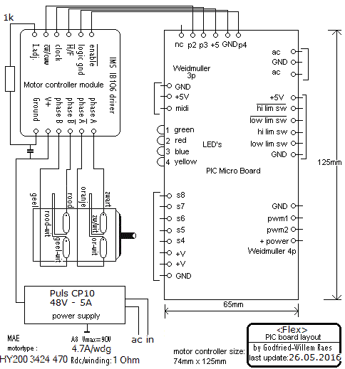
- 01.02.2007: Inkoop PTFE (Teflon) volstaf materiaal voor de vervaardiging
van nieuwe geruisloze loopwielen voor de zaagbladen.
- 31.08.2008: Ontwerptekeningen voor de tweede grote revizie.
- 19.04.2016: Old circuitry removed from Flex. The works on a complete revision
have started.
- 21.04.2016: Revision of the bow movement mechanics. Push solenoids and softshift
solenoids removed.
- 22.04.2016: Two V-belts (Gates QPIII XPZ 1800) bought to replace the silicone
belt we had originally for the bows. New design of the bow movement mechanism,
using a small Laukhuff bidirectional solenoid.
 Blocking
on a central position might become the problem now. Will we need a sensor
and a clutch as well?
- 23.04.2016: Test mount of the solenoid, the PCB and the IB106 motor controller
for the bows. Front bow mechanics finished. Start mounting the entire assembly
such that it can be tested as soon as we have the new firmware ready. The
midi implementation for the new version is bound to become incompatible with
the first version of <Flex>.

- 24.04.2016: Front bow assembly finished with the motor controller and the
PCB. .
 Start construction
of the back bow mechanism, virtually a copy of the front bow. Listing up all
requirements for the to be written new firmware.
- 25.04.2016: Start writing firmware for the front bow. Start rewriting the
testcode in GMT. Both codings go hand-in-hand of course. Here is the source
code for the frontal bow motor. Generating the clock frequency using timer3
and the low priority interrupt on the PIC 18F2525 works well. However, a lookup
table to obtain a good curve for motor speed seems required.
- 26.04.2016: New SMPS power supply modules ordered from Elipse. We will use
a single power supply module (rated 48 V / 5 A) for each stepping motor assembly.
Here is the datasheet for
the CP10.481 modules. Implementation of pulse coding for the Laukhuff's
to increase their attack power on changes of direction (e-Pi). First test
of the bow movement with the Laukhuff solenoids. We wanted to use two Penny
& Giles tilt sensors (type
STT280/60/P2) on the arms of the bows but had only one in stock. Unfortunately
Farnell does no longer distribute them and even after some searching, there
seems to be no other distributor... This is the same type we used in the robots
<Fa>, <Ob> and <Klar>.
A search revealed that alternatives could be the Murata SCA121T-D03 (-90 deg
to +90deg, two axis, Conrad order number 406069-89, cost 139 Euro), the Murata
SCA121T-D07 (-30 to + 30 deg., two axis, RS-Components, cost 154 Euro) or
the Posital Fraba ACS-020-2-SV10HE2-PM (-20 to + 20 deg. Conrad order nr.
1348298-89, price 298 Euro). We ordered two Murata's from RS-Components for
evaluation. This type has a 2.5V output for a zero degree angle.
- 27.04.2016: The bow movement solenoids need 28V to start moving from their
most extreme positions. Note that with the blades in place and the bows touching,
the extreme positions can never be reached, thus our measurement results reflect
a worst case scenario. Power supply redesigned. Look-up tables for bow motor
speeds calculated and integrated in the firmware.
- 29.04.2016: The two ordered Murata SCA121T-D07 sensors came in. Very expensive
components indeed...
- 30.04.2016: Design of a new PCB for the midi-hub board. This board carries
the 5V power supply module as well as the power-on relay.
- 01.05.2016: Finishing the PCB layout for the new hub board.
- 12.05.2016: PCB for the new hub board etched and drilled.
- 14.05.2016: Start soldering works on the new hub board.
- 17.05.2016: New chassis constructed for the left en right 'brains' side.
- 18.05.2016: The ordered Elipse power supplies for the stepping motors came
in.
- 22.05.2016: Construction of the chassis for the new DIN-rail mounted 48V
power supply modules. This time entirely made from stainless steel.
- 23.05.2016: Mounting of the Murata position sensors (SCA121T-D07) on the
bow arms.
- 24.05.2016: The sensors use the Y-output. The minimum voltage with the bow
to the left is 1.375 V, maximum voltage, bow to the right is 2.866 V. As the
ADC's on the PIC have 10 bit resolution, we have a resolution of 4.88 mV per
step. So the mimimum value will be read as 281 and the maximum as 587. Reduced
to 7-bits this becomes 35 and 73, the center position corresponding to 49.
- 25.05.2016: Debug session on the firmware for the bow controllers. Wiring
error on the motors remedied.
- 26.05.2016: Further development of the code for the bowing motors.
- 27.05.2016: Firmware for the backbow motor V1.0 ready and programmed into
the PIC. Tests on the isolated bow assembly. Ramping of the motor speed is
fully implemented now. Regulation of the position using a PID algorithm still
not optimal.
- 09.06.2016: Further works of the bow motor firmware taken up again.
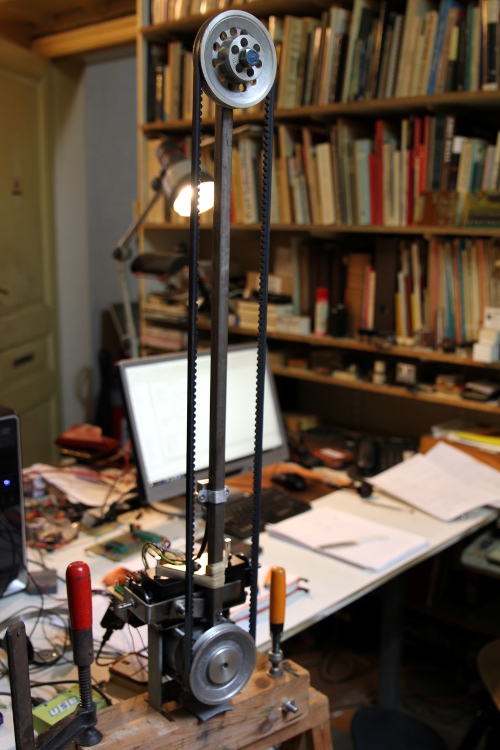
- 19-20.06.2016: Further work on the bow-control firmware. Now it works reasonably
well. First firmware version is for the backbow. This is the test setup on
my desktop...:
- 21.06.2016: variable ramping added in firmware: controller #44. Backbow
firmware considered ready. Start working on the firmware for the frontbow.
- 22.06.2016: Firmware for the frontbow up and running. Start wiring of the
boards for the saw bending motors. Midi implementation further worked out.
- 23.06.2016: Further work on the firmware for the Pi blade bending motor.
Midi implementation changed again. GMT test code adapted accordingly.
- 24-26.06.2016: Develpment of firmware for the saws
- 27.06.2016: Debugging and testing. Backbow placed back on the Flex robot.
Bowing seems to work, but requires collophonium.
- 28.06.2016: Further coding saw firmware.
- 29.06.2016: The timing diagram for the IB106 motor controller must strictly
obey this diagram:
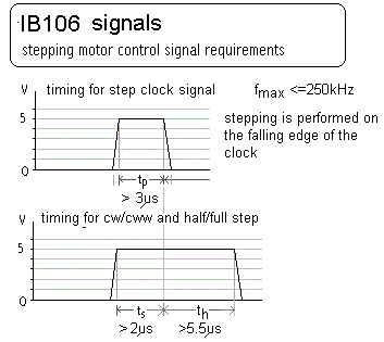 Note that motor steps are performed on the down edge of the clock signal.
Signals for the enable and cw/ccw commands should be applied during the high
state of the clock:
  All motion control and position monitoring now happens exclusively in the
timer3 interrupt service routine.(ISR). For ease of allignment and callibration
(this gets easily lost if due to high requested motor speeds and/or very fast
ramping we encounter motor stalling or slip) we added some extra note on/off
commands to the implementation: note 38 will fully stretch the Pi saw and
39 will perform this for the e saw. Note 40 will fully bend the Pi saw and
note 41 will do the same for the e saw.
- 30.06.2016: Awfull problems with the firmware. Position sensing and tracking
seems highly problematic and unreliable.
- 01.07.2016: Considering to use a proximity sensor to count revolutions of
the shaft itself rather than counting motor steps. Pepperl+Fuchs NBB2-V3-E2-V5
should do. We can connect it to the free A.2 port on the PIC controller.
- 02.07.2016: Start construction of a mounting bracket for two Pepperl+Fuchs
proximity sensors to be used as revolution counters.
- 03.07.2016: PCB for the Pi-Saw blade microcontroller modified such that
we can connect the new sensor.
- 04.07.2016: Further work on the saw blade firmware. Finally got it working
pretty well. The new problem now is that the bows push the TR24 thread away
from the rotation sensor... So, we may need to add some kind of guide or bearing
between the motor shaft end the place of the sensor. Could be bronze of even
Teflon. PCB for the e-saw blade modified the same way as we did for the Pi-saw
board. Firmware written for the e-saw board, merely a copy of the Pi saw firmware.
- 05.07.2016: The front bow bidirectional solenoid hinders movement of the
e-blade. So we had to cut off a part of the thread. Also there are still problems
with the centering of this bow. Strangely enough the back bow performs much
better in this respect despite same construction and firmware. Maybe we just
have to give it some more friction... Experiments performed with holders preventing
excentric movement of the TR12x3. These will have to be welded on the rails
for the cast iron wheels pulling and pushing the saw blades.
- 06.07.2016: Mounts for the beater motors on the front of the sawblades made
and welded on. We use Johnson motors, same type as used in <Chi>.
- 07.07.2016: Backside beaters for the e-saw reconnected and adjusted. Titanium
bolts and nuts traced: probolt-usa.com has them with part numbers MTIPB1060F
(M10 x 60 bolts) and MTIFN10 (M10 nuts). Price for two of them would be 46.18$.
A we lost all our subsidy, its not really an option anymore. These bolts would
considerably reduce the top-weight of the bows...
- 08.07.2016: Firmware for the saw blade microcontrollers modified. There
still is a bug causing interference between the PWM channels and stepping
motor control. Wiring fnished, spirawrap added where needed. Two pretty strong
push springs added on the M10 bolts that serve as a shaft for the cast iron
wheels. Spindle mechanism neetly oiled. It would all function a lot better
if we only had the money to buy new TR12x3 threaded rods...
- 09.07.2016: Further debugging of the thread firmware. Still not reliable.
- 10.07.2016: Yet another full day of firmware debudding and development.
Trouble with glitches on the rotation sensors solved in software. Precise
and reliable positioning remains problematic. The interference problem between
the motor control and the PWM for the Johnson motors is solved now.
- 11.07.2016: Finally we got the saw blade firmware up and running as it should.
However we encounter erratic behavior on stretching the blades...
- 12.07.2016: Testing and development of code for <Flex> in the Haram
production.
- 13.07.2016: Further tuning of the saw blade firmware. Most of the problems
with glitches were solved by properly grounding... Mosfet for the Pi-saw front
motor burned out as a result of motor stalling. Mosfet replaced and small
heatsinks for TO220 mounted on the PWM mosfets.
- 14.07.2016: We finally got the firmware to do what it should do. This be
version 1.4. Pi and e sawblade firmware flashed. Tested o.k. Testcode in GMT
adapted to conform to all implementation changes. Thread guide constructed
and welded on for the e-saw blade. This improves stability quite a bit. Constructed
protective plates in polycarbonate over the bow motor controllers and the
Laukhuff solenoids. This was done because the rosin falling off the bows sticks
too much to the solenoids and the board. Cleaning the plates regularly with
some alcohol will be required now. A little humor added: Flex now got a dented
tail.. maybe we can make it wave... Some new high resolution pictures made.
- 15.07.2016: Rehearsal session for the 'Haram' production with a central
cole for <Flex>.
- 16.07.2016: Still not pleased with the sound of the bows. So we performed
an experiment by glueing 9 mm wide strips of real animal parchment on the
outer side of the V-belts. In an experiment done with a straight piece of
V-belt, this worked pretty well as bow material. However, the parchment revealed
not elastic enough to bend over the bow wheels without breaking. We prepared
strips of ca. 600 mm each. Would it be possible to use many pieces of shorter
strips? Or should we have used much thinner parchment? The problem here is
that the strips easily come off the belt. The idea of using parchment is not
a novelty in itself, as it was used according to different sources as a covering
material for the bow wheels in hurdygurdies. Obviously though, the hurdy gurdy
uses a wood wheel and the elasticity problems there is not an issue.
- 17.07.2016: Parchment and glue removed again from the bows... Reheasals
with Flex for the Haram production.
- 18.07.2016: Extra ground connection made from microswitch grounds to chassis.
Seems to solve the glitch problem.
- 19.07.2016: Premiere performance of the Haram production with its central
role for Flex...
- 20-21.07.2016: Two more performances of the Haram production with a central
role for Flex.
- 23.07.2016: Further experiments with bow materials. Could we polish the
backsides of the V-belts to get rid of the ribbed structure of the rubber?
- 20.07.2020: Flex gets an important role in our 'Noli me tangere' production.
During the rehearsals, the weld on the bar connecting frontwheel with back
wheels broke. So replaced it with a new one, a bit longer (770mm) , such that
welding was not required for the repair. This bar is now regular steel, 30
x 5 x 770, with two holes 12 mm diameter. We still need to find a better material
for the bows.
- 18.08.2021: In working on a stand-alone controller for Flex and testing
it in an interactive mode, we got a smoke stack from the PCB's underneath...
Some analysis revealed that this was not caused by a failure of <Flex>
but by an accidental midi-feedback condition, causing a loop of power on/off
commands at a rate of ca. 260 times a second... The IRL640 steering the frontal
beater motor on the e-blade went to heaven.
- 19.08.2021: Burned IRL640 replaced with IRLZ34N. E-saw PCB thoroughly checked.
Work on <Flex> as a stand-alone robot can continue now. We hope to get
it ready in time for the exhibition in SMAK opening september 2nd.
- 25.08.2021: Axo-board programmed to steer <Flex> for stand-alone operation.
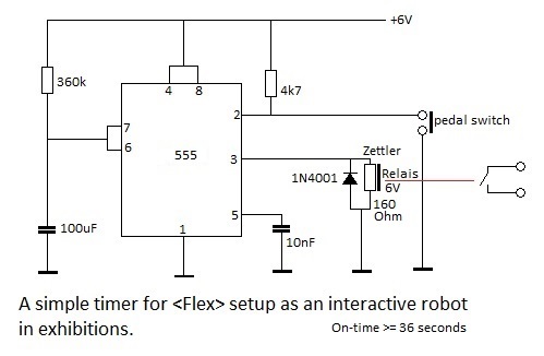
- 28.08.2021: Timer circuit designed and soldered such that visitors to the
exhibit can start <Flex> and let it play for 36 seconds. Here is the
'legacy' circuit:
- 02.09.2021- 26.09.2021: <Flex> exhibited at the SMAK museum in Ghent.
- 27.09.2021: After playing uninterrupted for 25 days, <Flex> returned
to the robot orchestra in perfect condition.
TODO:
- construction of a soft beater mechanism for the beater motors. Improving
the mechanism.
- adding lights and spring limiters on the bow assemblies
- fixing the stainless steel board holding the saw motor controllers to the
chassis with a couple of bolts.
- Final testing under GMT
- rewriting demo code.
- replacing the TR24 threads with straight new ones...
- replacing the M10x60 bolt on the top of the bows with a titanum one.
Afmetingen & andere technische specifikaties:
- hoogte: 1500 mm
- breedte: 600 mm
- lengte: 1600 mm
- gewicht: 136 kg (checked 07.2016)
- elektrische aansluiting: 230 Vac - 1000 Watt.
- data-poort: MIDI (1 input, 4 thru outputs with differential midi)
- Midi implementatie: zie tabel bovenaan deze pagina, onder de engelse introduktietekst.
- Verzekeringswaarde: 24.000 Euro.
Design en konstruktie: dr.Godfried-Willem Raes
Atelier medewerkers:
- Bert Vandekerkhove (mechanics)
- Moniek Darge (painting)
- Leonaar Degraeve (requisites)
- Kristof Lauwers (GMT-coding, Axo-code)
- Johannes Taelman (PCB design)
- Mattias Parent (workshop assistence)
Music Composed for <Flex>:
- Godfried-Willem Raes 'Flexes' (2002) [not yet ported to work with Flex version
2]
- Godfried-Willem Raes 'Flexing Haram' (2016)
- Kristof Lauwers 'Flex demo'
(2016) [MP3 file]
- Godfried-Willem Raes 'Noli me tangere' (2020)
Robody Picture with <Flex>:

Emilie De Vlam en Godfried-Willem Raes (foto Bart Gabriel),
Flex version 1.0, 2002.
Some pictures from performances with
Flex version 1.0.
Last update: 2021-09-27
by Godfried-Willem Raes
Service manual:
Flex can be taken apart for servicing into following modules:
- first bow motor assembly with inclination sensor and controllers (front
bow)
- second bow motor assembly with inclination sensor controllers (back bow)
- Pi-blade horizontal movement assembly with end sensors
- e-blade horizontal movement assembly with end sensors
- wheel-base, also holding the rotation sensors
- power supply modules (4x 48V, 1 x 12V)
- midi I/O and light control board. This board also carries the 5 V power
supply.
1.- Overview:
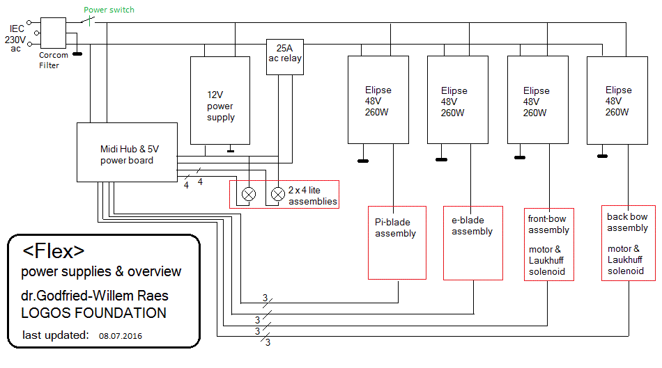
2.- Wiring diagram for adressing of flex components:

Source code for the front bow PIC controller
Source code for the back bow PIC controller
Source code for the Pi-blade PIC controller
Source code for the e-blade PIC controller
Source code for the Midi input and hub
board
Circuit diagram for the motor control boards: (<Flex> uses four of these
boards)
These are the boards for the movement of the Pi and e blades:

These are the boards for the two bow motors:
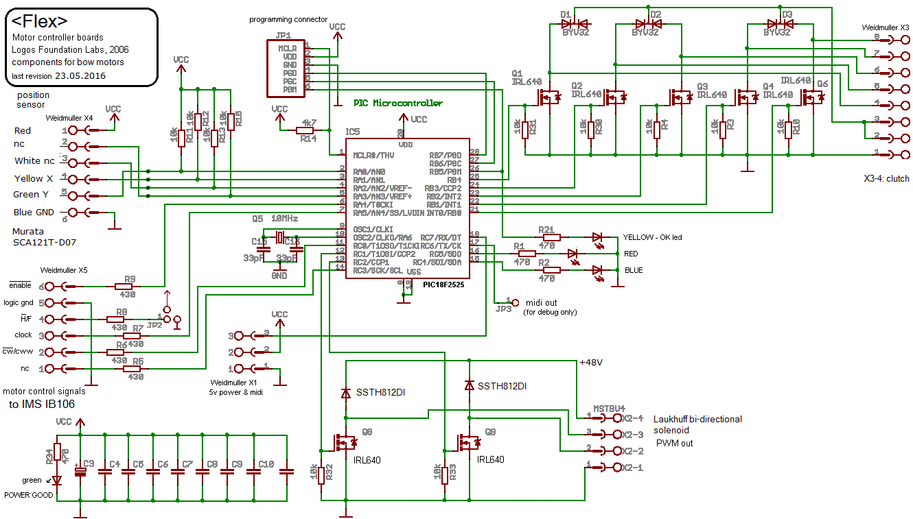
3. Calculations for trapezoidal threads and bending position:
Thread length: 100 cm, diameter 12 mm. Material: Stainless Steel. Type TR12x3
Total number of revolutions: 335 (thread speed), or 67000 stepping motor full
steps. The HY200 motor has 200 steps per revolution.
Usefull length in <Flex> = 70 cm or 234 revolutions. (= 46800 stepping
motor steps)
So, at 5 Hz rotation speed (= 5x60=300 rpm), we have a linear displacement
velocity of 1.5 cm/s. In order to get a speed of 1 second for the full 70 cm
traject, we would need a rotational speed of 234 Hz (= 14000 rpm). However,
the maximum motor-speed will be ca. 1500 rpm, so the linear movement will be
limited to 7.5 cm /s.
In the first implementations in the microcontroller we tried to keep track
of the position by counting the motor steps (incrementing or decrementing according
to the direction of rotation) in the interrupt code for the timer used. A word
variable was used, so 16 bits unsigned. However, the midi pitchbend command
is limited to 14 bits. Thus one unit of position in pitchbend format corresponded
to four steps for the motor. Hence the usefull range for the pitchbend command
became 0 to 11700. After many attempts to get this working, we gave up. Slipping
and motor stalling seemed to be an unavoidable source of accumulating errors.
Hence we mounted sensors on the TR12 spindles to count the really performed
rotations. As a consequence the precision of the positioning is now limited
to 1 rotation, corresponding to a linear displacement of 3 mm.
4. Solenoid data:
Bidirectional solenoids: August Laukhuff, trakturmagnet 24V, Force 24N. (in
<Flex> these solenoids are operated on a 48V power supply, using PWM).
5. Bow belts: GATES QPIII XPZ 1800. These must get collophonium in order to
bow well. The easiest way to apply rosin is by dissolving colophonium powder
in alcohol (ethyl or methyl) and applying the liquid with a small paint brush.
Wait for the alcohol to evaporate before using the bows again.
6. Stepping motors: MAE HY200 3424 470 A8. Current: 4,7 A/phase, 8-wires. Holding
force: 193 Ncm. In full-step mode the motor does 200-steps/rotation. Hence,
for 60 rpm we need a clock frequency of 200 Hz. For 1500 rpm we need a clock
frequency of 5000 Hz
7. Power supply modules:
- 4 x Elipse CP10.481. 5 A / 260 W each. (total cost: 673 Euro). Datasheet.
- 1 x XP-Power type ECE10U05 (5 V / 2 A), module soldered on the midi-hub
board.
- 1 x 12 V / 15 A power supply
8. Tilt sensors: Penny & Giles, STT280/60/P2. Datasheet
or Murata SCA121T-D07 [Datasheet].
9. Inductive proximity sensors:
Pepperl+Fuchs NBB2-V3-E2-V5 (used as revolution counters on the TR12x3 spindle)
10. End sensors: 4 x microswitch with rollers.
11. Power-on relay: PCF-112D1M (12V coil voltage, 25 A switching current).
12. Titanium M10x60 bolts: probolt-usa.com Part number MTIPB1060F and MTIFN10
(M10 nuts).[not yet mounted]
13. Connectors used on the PCB's (Weidmueller
/ Imo / Phoenix contact)


 .
Tests met aaneensmelten van de elastomeren voor het boogmateriaal.

 Note that motor steps are performed on the down edge of the clock signal.
Signals for the enable and cw/ccw commands should be applied during the high
state of the clock:
  All motion control and position monitoring now happens exclusively in the
timer3 interrupt service routine.(ISR). For ease of allignment and callibration
(this gets easily lost if due to high requested motor speeds and/or very fast
ramping we encounter motor stalling or slip) we added some extra note on/off
commands to the implementation: note 38 will fully stretch the Pi saw and
39 will perform this for the e saw. Note 40 will fully bend the Pi saw and
note 41 will do the same for the e saw.


