Pressure pads as interfaces for musical instruments
a report
Godfried-Willem Raes
post-doctoral researcher
Ghent University College & Logos Foundation
2007Since a couple of years so called FSR's (6) appeared on the electronic component market. These devices made of thin foil and generally with a self adhesive backside, react to mechanical pressure with changing resistance. It sounds like an almost trivial idea to try to use these components to implement a pressure sensitive keyboard or keypad assembly of some kind. To make a complete piano-style keyboard this way did'nt make a lot of sense in our opinion, since to do that professionaly, some form of force feedback from the keys seemed mandatory. Thus we decided to keep things simple and to design an experimental pad controller consisting of 8 FSR pads plus two additional thumb operated push switches. The signals from each pad are sampled and brought out as midi controller values. We limited the design to 8 pads just to keep interfacing to an ARM microcontroller (with 8 AD inputs) as straightforward as possible. The perspective of the controller was dual: First we designed it such that it could be used as a controller in the context of our ever growing robot orchestra but, secondly we wanted to be capable of using it for our scientific research into the micromotoric of human expressive gesture. Reliability and reproducibility of results are important design constraints for both aspects, but a very high resolution (exceeding the possibilities of motoric control) as well as speed, are much more important in the scope of the second aim. Put in numerical terms, the last mentioned scope dictates a resolution of 10 bits and a sampling rate (per channel) of at least 250S/s. As to the first one, 7 bits resolution and about 32S/s seemed appropriate. In the project as described here, both goals were achieved.
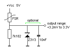
As things go, here too we started of by performing some measurements on the FSR devices. When no pressure is excerted on them, their resistance value is higher than 10MOhm. For a very gentle touch, this value comes down to between 600kOhm to 1.2MOhm. For really very strong fingerpressure, we got 3k7 as a lowest result. Response time was pretty fast. So designing a suitable input circuit for interfacing this to the ADC inputs of the ARM processor (input range 3.3V, 10 bit resolution) is pretty simple:
With this circuit the values read out will be proportional to the excerted pressure and cover the entire range of the sensor. Since the ADC inputs -after the spec sheet- can resist 5V on their inputs, no special protection seems required. Of course it would be harmless and safe to put a 3V3 zener diode across the 7k18 resistor. For more noise reduction and integration, one could also add a capacitor at that place. We assumed an input impedance larger then 100k on the side of the ARM processor and for this reason did not consider adding opamp buffers in the input design.
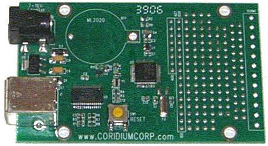
The ARM processor used, the LPC2103, a 32 bit processor clocked at 60MHz, is mounted on one of the development boards produced by Corridium Corp. It is shown in the picture below:
The board can be programmed in Basic. The firmware for this board can be downloaded freely for examination. The data rate for our controller applications is limited intentionally to 256 midi messages per second, but by leaving out the pacing commands in the source code, can easily be driven up to ca. 2000 messages a second, equivalent to a per channel sampling rate of 250S/s, as required for research purposes. If this is implemented, however, the receiving PC may get in trouble handling the midi data flow. One can also use the USB port to handle this data rate.
A procedure for the receiving end is part of our public domain GMT library g_lib.dll (source code module g_midi.inc) running on the Wintel platforms. (5)
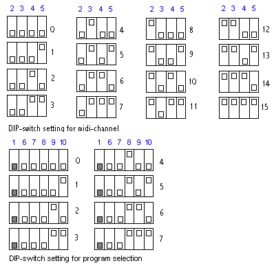
On the main board, there are DIP switches allowing the selection of the transmit midi channel, as well as for the selection of one of the maximum 31 programs and mappings in the firmware.
Programs available in the firmware are:
- Program 0: disabled
- Program 1: Data rate 256 bytes/s Midi encoding using key-pressure commands. Data is only send whenever there is a change in the pressure felt by any of the pads. The switches are send as controllers 70 and 71. When the switches are pushed, the value output is 0, else it is 127. In the procedures for midi-input, we inverted the data to make it more intuitive. The scan rate is limited to 32 scans/s.
- Program 2: Scan rate max. 1000 scans/s. Encoding using key aftertouch commands.
- Program 3: Continuous sampling. To be used for scientific research purposes. This allows FFT's to be performed on the data. The scan rate is 125 Scans/s.
- Program 3: direct mapping of the device to our <troms> robot
- Program 4: direct mapping of the device to our <simba> robot.
- Program 5: direct mapping of the device to our <rotomoton> robot
- Program 6: direct mapping of the device to our <thunderwood> robot
- Program 7: debug and research mode. The data are sent to the connected PC via the USB port. Used for monitoring and adjustment.The scan rate is 125 Scans/s.
- Program 8-31: for later development.
Complete circuitry
The practical circuit drawing for the complete sensor assembly, realized on a piece of prototype board, looks like:
Although drawn in this schematic, we did not mount the 3V3 zener diodes, as in practice we could not exceed the 3.3V limitation on the AD inputs with any normal finger pressure. The practical value used for the 7k2 resistors (a non standard value...) was taken as 7k32. The green LED, mounted on the front of the console, lights up when midi output is generated from the interface.
Mechanical constructionSince physical forces ought to be excerted on this controller, it ought to be build such that it can at least withstand the totality of the forces involved in actual musical performances. Also the mechanical construction should be free from own resonances. For these reasons we constructed the chassis from pretty thick stainless steel, welded together to form a sturdy unit.
As to the precise placement of the pressure pads, this issue really gave us headaches. We wanted a device that would be pretty universal in its useability to all kinds of people, yet, peoples hands seemed to be just as different than people themselves... We made 'handprints' of a good 50 people, male and female, asking them to put their hand on a piece of A4 sized paper and to place the fingertips such that they would feel comfortible to push with every finger more or less independenty. (I must say that most of the people we asked were professional musicians...) The results were then averaged out, but the variation was much larger than we had expected. The proportions we arrived at became as bad as democracy: the majority judgement leading to a one-size fits nobody at the end... It became clear that this type of controller should really become custom designed and different for every user. Since the pads are self adhesive, it would'nt be too difficult, in a commercial production batch, to do this for every single order.
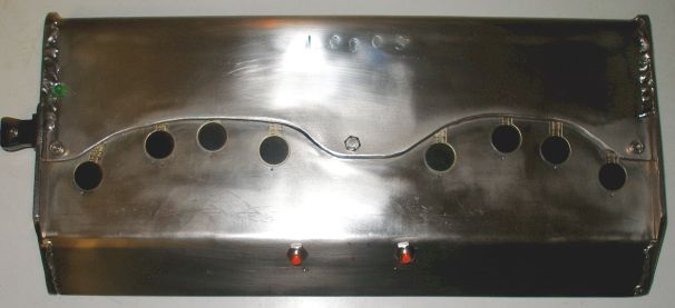
The prototype as we made it looks like:
The power supply connector as well as the midi-out socket are on the left of the pressure pad console. All circuitry fits nicely underneeth inside the console.
Artistic applications:
Following composers have contributed pieces to be performed using out <Handy> interface:
- Godfried-Willem Raes "Handy Troms", for the <Troms> robot and the <Handy> controller (2007)
- Kristof Lauwers "Goldfingers" (2008)
- Hans Roels -under development (2008)
- Godfried-Willem Raes "Sire's Hands", for the <Sire> robot and the <Handy> controller (2008)
Notes:
(1) Pretty complete catalogue of all our automated and other instruments.
(2) Composers guide to the M&M robot orchestra
(3) More texts by the author with regard to robotics and sensors
(4) Expression control in musical automates.
(5) articles on sensor technologies used to translate expressive properties of human gesture into data that can be used to control automates and other sound generating devices.
(6) FSR stands for 'Force Sensitive Resistor'
Credits & Acknowledgments:
Part of the research results presented here where obtained thanks to the support of Hogeschool Ghent, where I am currently half-time employed as a post doctoral researcher, paid 70% of a normal wage however..
Thanks to the Logos Foundation, funded by the Flemish Government, where my instrument building workshop and electronic research lab are based. They also provide me with all facilities to bring this research to artistic and presentable results.
Manufacturers of devices treated here:
- CP0151 FSR's
Bibliographical references:Pallas-Areny, Ramon & Webster, John G. "Sensors and signal conditioning", ed. John Wiley & Sons Inc., NY, 1991, ISBN: 0-471-54565-1
Sheingold, Daniel H. "Transducer Interfacing Handbook", ed. Analog Devices, Norwood, 1980 ISBN:0-916550-05-2
First public appearance on internet: December 2, 2007.
Last revision: February 25, 2008
The 'Handy One' interface used by Moniek Darge in the Brussels M&M performance, february 2008:


