Rotomoton
automated percussion

Version 1.0 - archive file

2000/2006

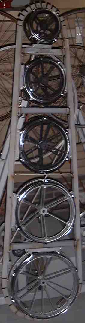
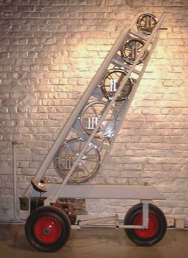
This instrument is a computer controlled assembly of five rototoms. Each drum is equiped with beaters and the pitch of each rototom can be controlled. The lowest couple of rototoms have 3 beaters each, whereas the upper three suffice with two beaters each. The beaters are velocity sensitive and have full 16 bit dynamic control. Heavy duty stepping motors are used to achieve pitch control of each individual drum. Instead of rotating the drums on their fixed axis, we fixed the frames of the drums and rotate the threaded axis through a geared construction using dented belts. This also contributes to silent operation of the mechanics.

The instrument can be played by standard MIDI commands, straigth or using our GMT software in which case it is also capable of listening to pure algorithmic commands, bypassing the inherent slowness and low dynamic/timing resolution of the midi protocol. Particularly precize control of stepping motor movement and hence, pitch changes of the drums, requires a very high data rate impossible to achieve using midi.

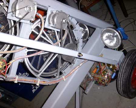
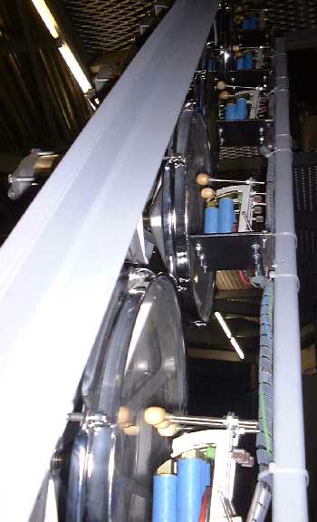
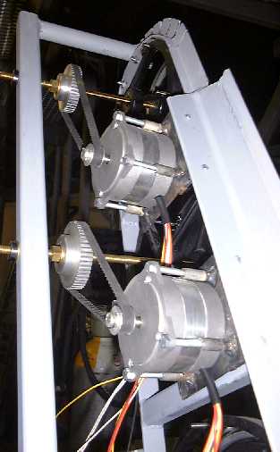
The picture above gives an idea of the construction of the beater side of <Rotomoton>. The construction of two of the five stepping motors can be seen on the picture below. The picture was taken with the position sensors rermoved.

<Rotomoton> uses dedicated hardware, designed for musical automats such as player pianos, percussion instruments, organs and even bowed instruments. Details can be found in our course on experimental music on this same website.

The original (version 1) hardware consisted of following printed circuit boards:

1. a parallel bus-board, designed for many of our automated instruments. (cfr. Klung, Player Piano, Harma, Springers, Troms, ThunderWood, Gorgel, Troms...) This board gets its input from a parallel printer port or from a National Instruments DIO device (PCI card or PCMCIA card) from a stardard wintel PC running Window98 with MMX command set and multimedia timer features. Under Windows NT or Windows2000, only the NiDAQ version should be used. However, it is also possible to use any other microprocessor or controller as long as it can implement centronics like outputs. The pc board for this circuit contains the 5V regulator used for the digital signal sections on the other logic boards as well. To see this circuit, a demultiplexer, click following link: bus-board schematic

Two bits of the velo-bus are used to select the timer chips for the beaters, the note bus is used to drive the individual coils of the stepping motors as well as the DAC's used for pulse width modulation for tuning the rototoms. The lights are also controlled by the note bus.

2. Beater driver board. This pc board houses the power mosfets used to steer the solenoids used for activating the sound sources. In this instrument we used individual programmable 16 bit timers for each beater. The timer chips used are Intel 82C54 types. [ comment on these circuits, first developed for our first generation player pianos can be found at http://www.logosfoundation.org/kursus/2116.html. ]

3. The power mosfets we used for controlling these solenoids are Harris RFP4N12L (equivalent to IRL640), since these switch on TTL levels and are capable of dissipating the required currents. Note that when the power suppy is switched on, all latches may go to a high state, thus sounding all notes at the same time. To avoid this, either first start the computer and the appropriate GMT program and then switch on <Rotomoton>, or start Rotomoton with the provided dummy connector inserted in the input port.

4. The stepping motors use special circuitry, shown below. Since in this application, very high force but no holding torque is required from the steppers, we designed the circuit as a single pulse driver. The pulsewidth for the pulse applied to successive windings is software programmable. (range about 2 to 23 ms). Since the motor current can be quite high, the mosfets (RFP10N15L types) had to be mounted on individual heatsinks. Therefore they could not find a place on the board but are mounted on a large discrete panel under the motors directly. The mosfet assembly together with a motor can be seen on the picture, although the heatsinks are masked by one of the contruction bars.:

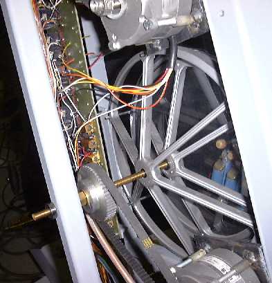
The dented wheels are selected as follows:

  motor shaft number of teeth drum axis wheel number of teeth belt type maximum stepfrequency nr. of motor steps required for one revolution of the drum axis
smallest drum (Sop) 12 42 220XL 500Hz 700
second drum (Mez) 12 48 180XL 450Hz 800
third drum (Alt) 12 48 200XL 450Hz 800
fourth drum (Tenor) 12 60 220XL 350Hz 1000
fifth drum (Bass) 12 72 210XL 350Hz 1200


Five bits are used to read the end position of the tending mechanism, one for each drum. Microswitches are used as sensors. These may be replaced by optical sensors later on, since our microswitches suffer from great hysteresis. For precize positioning, it is mandatory to reset all motors to the lowest end position prior to running music compositions. Software to handle this automatically has been integrated into our <GMT> language. Technical exploded drawing showing the construction of the tuning mechanism driven by the stepping motors:

5. The power supply for this instrument is rated for 690Watts. Two transformers are used: 230V/12V - 630VA and 230V/24V 60VA.


In 2006, Rotomoton has undergone a complete revision of the hardware. It now uses 5 PIC controllers, one for each rototom.

As other instruments belonging to this <Slag-Werk> project, this one also is designed for mobile use and thus mounted on sturdy steerable wheels, the back of which can be seen on the picture.

Music:

If you are using <GMT> under Power Basic, you can use all specific hardware control functions and procedures provided in our library. A midi command converter was written by Kristof Lauwers. Rotomoton can also be controlled using network UDP/IP commands. The low level midi and hardware mapping of the different components of <Rotomoton> is:

  • Solenoid beaters ( from low to high rototom):
    • Drum 1: notes 48, 49,50 (beaters from center to rim)
    • Drum 2: notes 51,52,53
    • Drum 3: notes 54,55
    • Drum 4: notes 56,57
    • Drum 5: notes 58,59
    • Lights: notes 114,115
    • in music staff notation:
  • for drum rolls:
    Note on followed by note aftertouch. The repeat frequency (in Hz) will be: (0.1 + 30 * aftertouchvalue / 127 ) for the highest three drums; (0.1 + 25 * value / 127) for the lowest two. The velocity can be changed during the drum roll by sending a note on with a different velocity. The drum roll continues until a note off for that note is received.
    • Drum 1: note 41 + aftertouch
    • Drum 2: note 42 + aftertouch
    • Drum 3: note 43 + aftertouch
    • Drum 4: note 44 + aftertouch
    • Drum 5: note 45 + aftertouch
  • Stepping motors:
    You can tune the drums by sending controllers 101 to 105 (from low to high).
    • Drum 1: controller 101, values 1 - 127 mapped over a fourth
    • Drum 2: controller 102, values 1 - 127 mapped over a fourth
    • Drum 3: controller 103, values 1 - 127 mapped over a minor sixth
    • Drum 4: controller 104, values 1 - 127 mapped over a major sixth
    • Drum 5: controller 105, values 29 - 127 mapped over an octave + minor third.


    New commands added in 2006 (Version 2.0):

  • Reset Drum 1 to lowest position: controller 91: value > 0 - value = %False = cancel command
  • Reset Drum 2 to lowest position: controller 92: value > 0
  • Reset Drum 3 to lowest position: controller 93: id.
  • Reset Drum 4 to lowest position: controller 94: id.
  • Reset Drum 5 to lowest position: controller 95: id.
  • Set Drum 1 to Highest position: controller 111: id.
  • Set Drum 2 to highest position: controller 112: id
  • Set Drum 3 to highest position: controller 113: id
  • Set Drum 4 to highest position: controller 114: id
  • Set Drum 5 to highest position: controller 115: id
  • Calibrate range drum1: controller 121: id.
  • Calibrate range drum 2: controller 122: id.
  • Calibrate range drum 3: controller 123: id
  • Calibrate range drum 4: controller 124: id
  • Calibrate range drum 5: controller 125: id.


Under <GMT> following procedures and functions are exported specifically for controlling <RotoMoton>. The code resides in the DLL g_nih.dll or g_noh.dll. Source code is in the module g_h.inc.

  • Roto_Light (lightnr AS BYTE, onoff AS BYTE)
    • lightnr: should be 1 or 2, onoff should be either 0 or 1
  • Roto_Rot (BYVAL drumnr AS BYTE, direction AS INTEGER)
    • drumnr: should be 1,2,3,4,5
    • direction: -1 turn downwards, +1, turn upwards
  • Roto_Init_DLL (BYREF Rotomoton AS Rotomoton)
    • Rotomoton is a structure defined in gmt_type.bi and is initialized with the proper parameters for the automat on the first call of this procedure. Consult software guide.
  • Roto_Beat (beaternr AS DWORD, force AS DWORD)
    • This procedure pulses the solenoids. The pulse timing is controlled by the force parameter. It programs the hardware timers in the automat.
  • Roto_Push(beaternr AS DWORD, onoff AS BYTE)
    • This procedure can be used to move the beaters against the drumskin, for special effects. Every call to RotoPush with onoff set to %True should be matched with a call to Roto_Push with onoff set to %False.
    • beaternr corresponds to midi notes 48-59 as described above.
  • Further coding examples can be found in the <GMT> application module rotomo.inc.

    Composers working on pieces for <Rotomoton> sofar, include: Godfried-Willem Raes ('Rotstuk' voor Rotomoton), Michael Manion, Moniek Darge, Kristof Lauwers, Rene Mogenson ('The swarm breaks through the net'). Rotomoton is a fixed member of the M&M ensemble and as such also performs in orchestra pieces such as 'Technofaustus', 'Gestrobo', 'Picrada', 'STOvSQE4MM' , "Quadrada" by Godfried-Willem Raes and many other pieces.

    At this moment (since 11.2004) Rotomoton is undergoing a revision partuclarly aiming at improving the pitch sliding speed and avoiding the need of a laptop computer as dedicated server for rotomoton. The new design will make use of at least five PIC controllers. It should be operational again by the end of october 2006.

    Collaborators:

    • Filip Switters (TIG welding)
    • Xavier Verhelst
    • Moniek Darge (painting)
    • Kristof Lauwers (GMT software simulator implementation)

    Dimensions:

    • width: 1500mm
    • height: 2100mm
    • depth: 600mm
    • weigth: 220kg
    • power consumption: 690Watts / 230V AC
    • data input: centronics parallel port from Wintel PC or National Instruments DIO card. New version: midi input.

    Insurance value: 17.000 Euro.


    Construction of this automated instrument started august 2000 and was completed in its first working version around easter 2001. Rotomoton played its first scales on april 26th of 2001. It is now a permanent robot member of the Logos <M&M> ensemble. Its hardware was completely revised and rebuild in 2006.


    The picture on the left shows the first step in the construction of <Rotomoton>: the assembly of the five rototoms in a TIG-welded frame.

    The final instrument is shown on this picture:

    The <Rotomoton> automat can be heard on the Logos Public Domain CD <Automaton> (LPD007).

    Revision 2005-2006

    Last updated: 2006-09-19 by Godfried-Willem Raes