Tape recorders as musical instruments
a report
Godfried-Willem Raes
postdoctoral researcher
Orpheus Institute & Logos Foundation
2015 - 2023The analog reel to reel tape recorder
A detailed description of the analog tape recorder would cover more than a single volume book. Moreover, such books are available in archives worldwide. Some references are given in the bibliography. The essentials might be worth recapitulating here though. Moreover, it is quite essential for musicians to have a good insight in order to be able to perform quite some pieces using analog tape recorders.
Historical introduction
The historical invention of the magnetic recording principle is generally attributed to Valdemar Poulsen who invented and made a wire recorder in 1898 capable of recording telephone conversations. It used rolls of very thin steel wire and magnetization was straightforward, using a ring shaped electromagnet whereby the core ring was opened with a small gap through which the wire was lead with constant speed. The same electromagnet could be used for recording and reproducing.
It took until 1927 before this technique was improved with the invention of the bias current. Hereby an ultrasonic audiofrequency was mixed with the signal to be recorded causing the magnetic poles on the wire to switch much faster and thus enabling even the recording of musical signals. This bias current has been preserved throughout the entire history of analog magnetic recording technologies.
Only in 1935 the flat magnetic tape was invented and produced in Germany by BASF. An acetate tape was used, coated with a layer of magnetisable particles. This tape was used on the first German magnetophons and used by their broadcast stations. The audio quality was much better than that of the shellac records used worldwide. At the end of WW2, a few machines were smuggled out of Germany to the US, where they started copying them and producing similar tapes on their own (Ampex, 3M). Only in 1947 they succeeded in producing workable copies of the German invention.
From that moment on, the magnetic recording technology soon became the universal standard for professional audio recording all over the world.All tape recorders of professional quality consist of three motors: one for driving the capstan at a very constant speed (78cm/s at first, later 38cm/s), one for rewinding and one for fast forward and pickup force. Furthermore there are invariably three heads in the following order: erase head, recording head and playback head. The electronics consist of following essential circuit blocks:
- a bias oscillator (50kHz up to 180kHz, sine wave)
- a recording amplifier with proper equalization response
- a reproduction amplifier with an adapted equalization response (IEC or NAB)
- motor control circuitry
- a power supply
The most common tape format has always been 1/4" wide. For studio multichannel recordings 1/2", 3/4", 1" and 2" tapes were produced and used as well. Tape thickness had quite some variation as well. Long play tape, on a large reel, had a playing duration of some 45 minutes. Standard tape could hold only 30 minutes. Double play and tripple play tapes have been produced but never found applications in the professional audio scene as the effects of magnetic print-through were getting more and more severe with decreasing thickness of the tape. On professional machines, the bias current and the magnetisation level were to be precisely adjusted to the characteristics of the tapes used. Most studio recordings were kept and stored 'tail-out' (with the end of the recording at the start of the reel). The reason for this at first sight odd habit was that if print-through happened, it would come after the first layer of recording on the reel and not anticipating it. Another reason was that fast rewinding a tape after use -as required for 'tail-in-front' storage- was allways a bit more rough then taking up the reel after normal playback.
Professional equipment
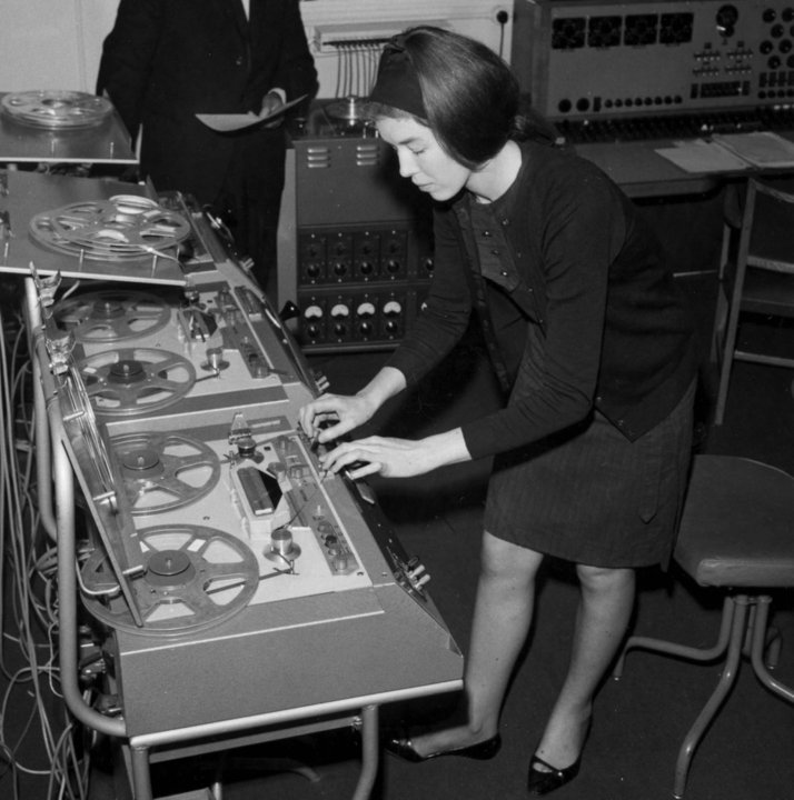
- For studio use: Telefunken, Philips, Otari, Studer-Kudelski. These machines, mounted on large consoles, were rarely leaving the studio. There are 1/4" as well as 1/2" and 1" types, 2 up to 16 tracks. Here is one:
And here we have Delia Derbyshire at work in the BBC radiophonic studio:
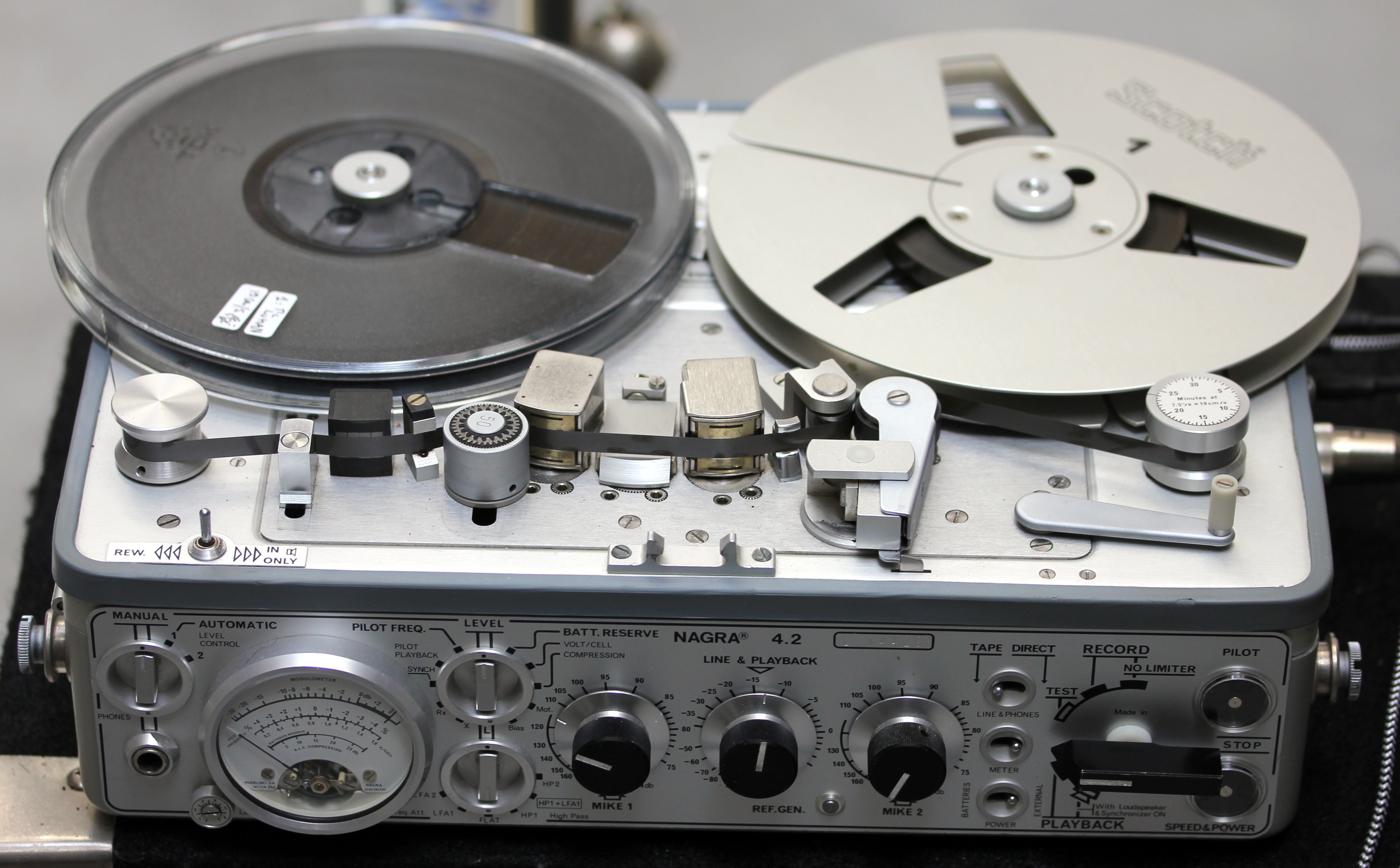
- For mobile use: Nagra, Stellavox. These were the machines of choice for radio reporters on professional broadcast stations around the world. The Stellavox machine was commonly used in the film industry.
- Uses in live electronic music: These machines had to be 'portable'.
Common types:
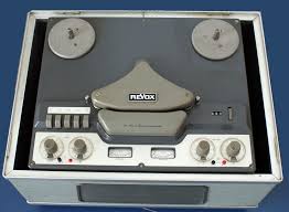
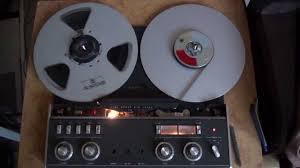
- Revox G36: Vacuum tube type first introduced in 1956. (service manual). Called 'portable', although with it's 22kg not a lightweigth.
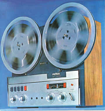
- Revox A77: Transistorized version (1967 - 1977)
- Revox B77 (introduced in 1978)
- Revox PR99: Latest professional model produced.
- Fostex R8
- Nagra: portable equipment, top quality but rarely used in live electronics because of the limited motor force and the extreme high cost.
- Stellavox: highly popular in the movie industry.
- Tascam
- Uher portable (The 'poor-mans' professional recorder...)
- Carad: A Flemish brand, using vacuum tubes. The most common model was full-track mono.
- Hencot, a French professional brand known for its unstable behavior
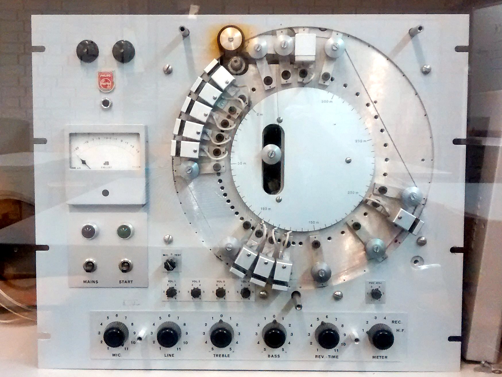
- Phillips: Phillips produced professional audio equipment and taperecorders for studios up to the late sixtees. Henk Badings and Dick Raaijmakers used them and also they were used to run Varese's Poeme Electronique in the Phillips pavilion on the World Exhibition of 1958 in Brussels.
Essential features: 3 motors, 3 heads. Speed: 19cm/s, 38cm/s, 76cm/s
Trackformat: Full Track (mono), Two-track (stereo)
Quartertrack (stereo) models were reserved for the amateur market and found little application in studios or live electronics.
Multichannel recorders (starting from 4-track on 1/4" tape) never really found applications in real-time performances. At the most, every so ofter a Teac, Fostex or Tascam 4-channel recorder was used for reproduction of pieces using quadrophonic audio.
On this picture: Pierre Henry in his studio between 1964 and 1971: .
And here we have a view on the WDR studio at the time Stockhausen composed his hymnen:
The tape recorder here is a 4-track 1" machine made by Telefunken.
Correction networks and standards:
Tape recorder heads are inductive devices and thus exhibit a non-linear frequency characteristic: the impedance goes up with frequency. Therefore at recording, a special equalisation is used compensated by a more or less inverted equalisation on playback. Europe and the USA used different standards: in the US, the NAB standard was in use and in Europe the CCIR (or IEC) standard.
European CCIR equalisation standards:
tape speed 76 cm/s 35 us 4547 Hz 38 cm/s 35 us 4547 Hz 19 cm/s 70 us 2274 Hz American NAB equalisation standards:
tape speed high low 30 ips 17.5 us 4547 Hz - - 15 ips 50 us 3183 Hz 3180 us 50 Hz 7 1/2 ips 50 us 3183 Hz 3180 us 50 Hz
Reel to reel analog tape recorders on stage...
Without any doubt the Revox series of reel to reel taperecorders have once been the workhorses for all contemporary music production involving electronic technology in the timespan 1956 to 1990. In the sixtees model G36 (model A was introduced in 1956!) was dominant (a very heavy, 22kg vacuum valve machine), in the seventies the A77 (produced from 1967 to 1977) model was predominant and in the eighties superseded with the B77 (introduced in 1978) and PR99 models.
On the picture below, dated 1970, we see Steve Reich experimenting for 'Drumming'. In the left of the picture we clearly see a Revox G36 machine.
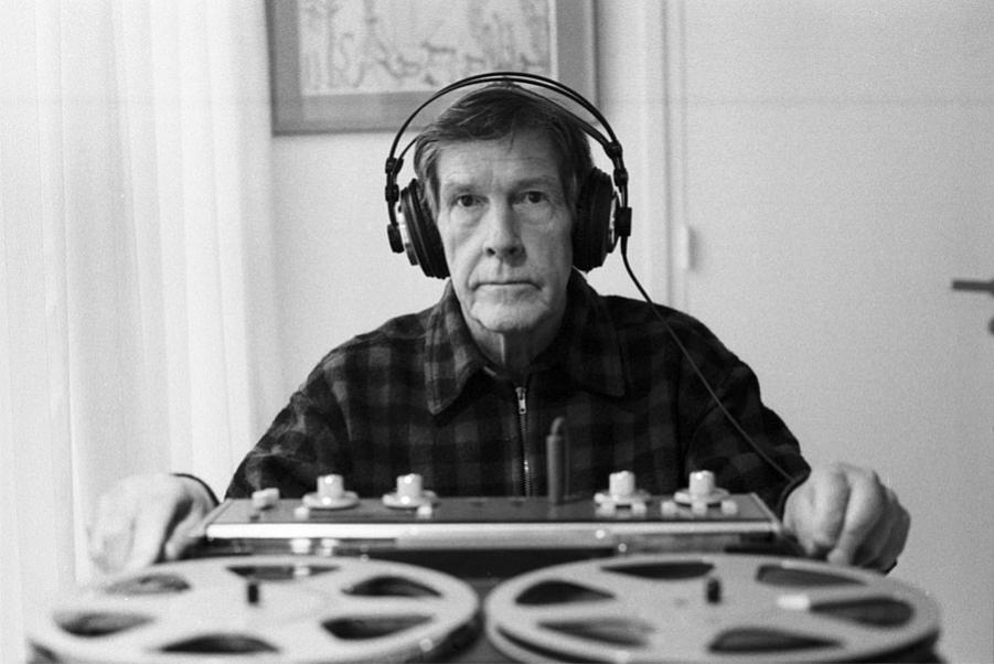
John Cage, using a Revox A77 is depicted here:
For all concert uses only the 2-track type, preferably with speeds 7.5 / 15 ips (19 cm/s and 38 cm/s) were to be used. Types with 9.5 cm/s and 19 cm/s speeds were also widespread. Their price was the same, but obviously by using lower speeds, one could save on tape expenses at the detriment of frequency response and dynamic range..
Taperecorders on stage as well as in studios were used in a broad range of applications:
- - playback of prerecorded tape material in combination with instrumental music making or performance. The term 'composition for instrument and tape' is today still used by quite many composers although the tape has long been replaced by an audio track on a computer... We cannot image any composer or performer today misses the often very loud 'click-clack' sound accompanying start/stop commands that used to plague so many concerts involving musician(s) and tape-machines.
- - use as an audio delay line. The minimum delay time is determined by the distance between recording and reproducing tape heads. With a minor preparation it was (and is...) possible to enlarge this distance by pulling the tape out between these two heads and feeding it through an external pulley.
- - use as echo and reverb machine: this was done by recording on one track and sending the (delayed because of the distance between recording and reproducing tape heads) reproduced signal back to the other channel, thus creating a delayed feedback system. Special machines have been produced for this purpose as well. These were equiped with multiple reproduce heads at slightly different distances. (Tape echo machines). Here is a picture of one such machines:
- - use for tape loops, using one or two machines. Some examples:
- Stockhausen's 'Solo mit Rueckkopplung' is a good and sophisticated example.
- Brian Ferneybough's Time and Motion studies.
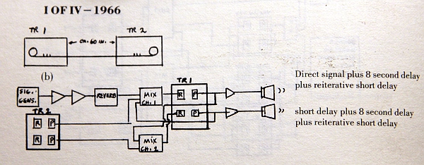
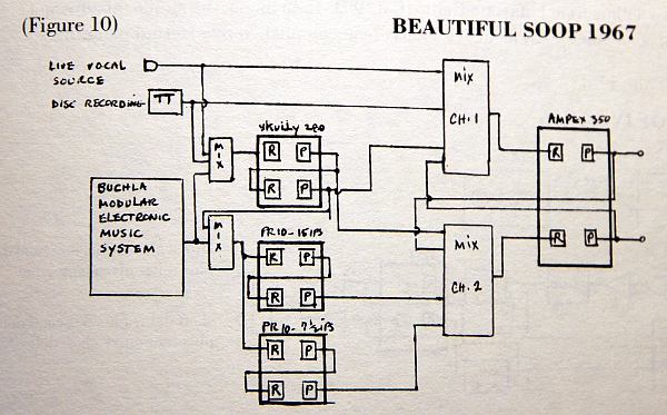
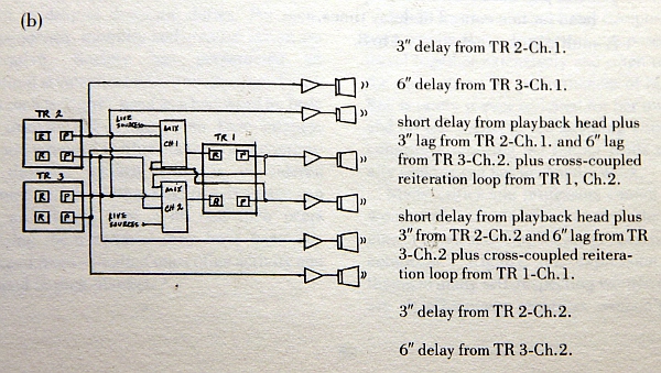
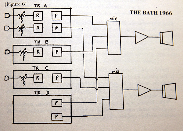
- Pauline Oliveros: 'The Bath' (1966), 'I of IV' (1966), 'Beautifil Soop' (1967)
- use for inverting sound and music by playing the tape backwards- - use for pitch transposition by changing either the capstan wheels or the capstan motor speed.
- - use to cause a phase shift, as no two machines run at exactly the same speed: used, amongst others, by Steve Reich to realize 'Come Out' in 1966. Possibly the first example of such use.
- - use as a generator of artifacts by causing interference between the bias oscillator and the input-signal. This was used by Richard Maxfield in 'Night Music' (1960). Maxfield connected the sawtooth (timebase) output of an oscilloscope to the input of the tape recorder and thus obtained difference tones in the audio range. The resulting sounds in this piece closely ressemble sounds of nature, insects, toads, bats and birds however, they are all pure electronic.
Although it is perfectly possible to replace these analog machines nowadays with digital, mostly computer based, technology we are convinced that in many cases an essential part of the performance gets lost by doing so.
However, using the old technology raises problems, as well functioning reel to reel taperecorders are harder and harder to find. In almost all cases the machines to be used will be between 60 and 30 years old and will be in need for maintenance and repair. Undertaking such a task requires a good knowledge of analog electronics as well as servicing experience, skills that are becoming rare.
Before starting repair or maintenance work on just about any taperecorder, first thing should always be to check the heads for wear. First clean them thoroughly with a soft piece of felt soaked in isopropyl alcohol (do not use methyl alcohol as it contains water, nor aceton as it may dissolve the insulation as well...) until their faces are fully shiny. Check for wear by observing grooves left by the passing tape. On new heads there should be no visible grooves at all. If the grooves are deep (let's say deeper than 0.2 mm) the heads need to be replaced as the reproduction of higher frequencies will drop seriously. It makes no sense to repair a machine with worn out heads as you will never manage to get it sounding the way it ought to sound. It must be said that it is very hard to find new head assemblies.
An essential part of maintenance on all reel to reel tape recorders consists in demagnetising the heads as well as all other ferromagnetic parts that come in contact with the tape. A simple tool is required to perform this task: a tape head demagnetiser:
This device simply consists of a coil with a fixed ferromagnetic core protruding from the coil. It connects directly to the mains AC voltage. It generates a strong magnetic field at the mains frequency near the tip of the protruding core. However simple the device, it should be used with care as touching the head surfaces with the tip can damage them severely. It should be held at very close proximity to the head for a few minutes, with the tape recorder switched off. Slowly move the demagnetizer towards and afterwards slowly away from the parts to be demagnetised. All three heads have to be treated but the most critical one is the reproducing head. Always do this with the machine turned off, as the voltage induced in the heads otherwize might overload and damage the preamplifiers in the machine.
Without a proper set of schematics, don't even try to repair a Revox or any other professional reel to reel tape recorder. The schematics as well as the service manuals are all available for download from the Studer website.
Here is a link to the circuits for the Revox A77 model on our own site.
Case reports on repairs performed by us on Revox tape recorders:
Revox model A77, 1972 2-track
This machine didn't do anything when switched on. First we discovered that the housing has a couple of pins that insert in a plastic cap covering the mains connection. They break the mains power as soon as the machine is removed from its cabinet. So first thing we did was inserting two bolts in these holes. This at least connected the machine to the mains power. But, this was not the real problem... We checked the 21V power supply to discover this voltage was absent. Not the 630mA fuse was blown, but the bridge rectifier appeared to be open circuit. We replaced it with a 4 A type mounted on the side of the chassis, as it was to big for the original PCB. Still it wasn't working, although the 21V power voltage was found O.K. now. Further checks revealed electrolytic capacitor C307 (250uF/25V) was shorted. Resistor R313 (39 Ohms) was found to be burned. We replaced both parts. The capacitor with one rated for a somewhat higher voltage.
Therewith the job was done and the machine back in operational condition.
Revox mode A77, 1975 2-track
On this machines the lights came on, the take-up and rewind motors worked as normal but the capstan motor appeared dead. At the most, on the switch on surge, it would move a bit and then stop again. The 21V power supply was checked and found out to be O.K. and within specs. We replaced the 3.5uF AC capacitor for the motor with the result that the motor started spinning, but way too slow and without any torque. We checked the tacho sensor with the oscilloscope and this worked O.K., however as soon as we reconnected it the motor started turning at a way to fast speed... This was going to be a tedious job, as this meant we had to remove the motor control board. Checking the board made us replace all electrolytics and tantalums with modern and fresh types.The power transistor driving the rectifier bridge in the motor control had a CE short. Its a 2N3583 in a cute TO66 package. Of course, this type is since long no more on the market. Looking up the specs, we decided to substitute it with a MJE13007 high voltage type. This one comes in a standard TO220 package and thus mounting and wiring had to undergo some changes. Still it wasn't working... We replaced the NE555 timer chip as well as the power transistor PNP driver (in the circuit specified as a BC178 but what we found soldered in was a BC308. This may have been an earlier repair... As we didn't have exact replacement parts in stock, checking the specs of the original transistor made us turn up a 2N3906. Before reassembling we checked the board's functionality by connecting a pulse generator (800Hz) to the tacho input, a lab power supply set to 21V. The board draws some 50mA. By connecting the speed switch wire (red) on and off the 21V we could verify the pin 1 output of the (obsolete and hard to replace) TBA931 reacting properly. The base drive for the power transistor changed accordingly. So far so good. We reassembled the board and fired up the machine again.
Success! It works again, the motor nicely spinning.As we noticed a little bit of popcorn noise on the outputs of the playback amplifiers, we replaced the following capacitors: C803 (1600uF) -here we replaced it with a 2200uF type, as 1600uF is hard to get on the market; C811 (100uF), here we inserted a tantalum polymer type; C814 (10uF); C813 (25uF), replaced with 22uF. Here is a view on the board before the replacements:
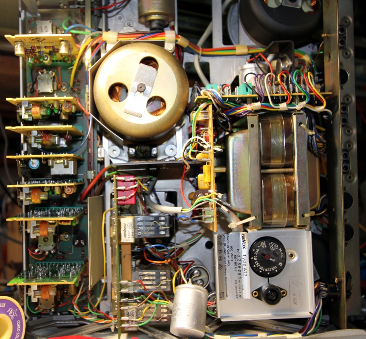
Here is a view on the internal guts of the machine:
The motor control board can be seen on the picture: it's the vertical board to the left of the transformer. The 21V power supply is on the board seen in top of the transformer. A final problem with this machine was that due to unthoughtfull treatment by someone not too familiar with fine equipment, the knob for the rotary turn-on switch was broken off. This obviously was not an electronic problem but nevertheless a pretty tedious one to solve. We had to make a new bus fitting over the 6 mm axle on the lathe in order to replace the knob.
Revox model A77, 1974 2-track
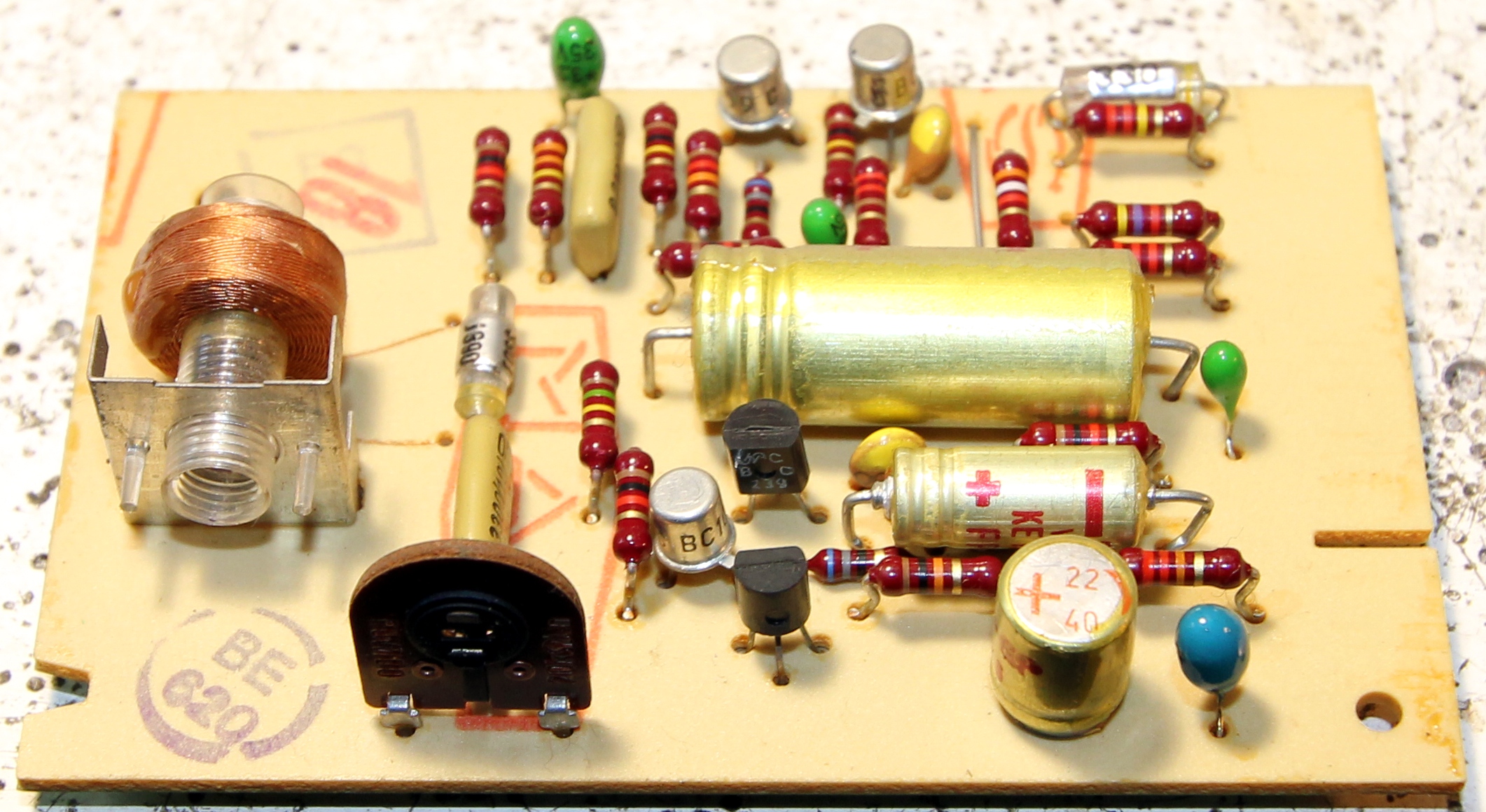
This machine was completely functional, except for the recording part. We checked the bias oscillator and found it working as it should. Then we suspected the board with the recording relais and indeed found R601 (10 Ohms) burned on the PC board. Capacitor C602 (470uF/6V) was measured and found to be very leaky. Here is a picture -showing clearly the burned resistor- of the board before the repair:
We replaced both and still it wasn't working. So we went on and checked the AC152 transistor. This one is no longer on the market anywhere. It's a Siemens product for which we digged up the datasheet: PNP Germanium transistor... The specs are pretty close to those of the AC128 (we had a box of these in stock) , so we gave it a try and performed the replacement. Replacing old germanium transistors is an allways recurring problem in servicing equipment from the sixtees and seventies, as these transistors are since long no longer in production. Never exchange a germanium transistor for a silicium one! If replacing with silicium is the only way to go, you have to redesign the entire circuit for operation within silicium boundaries. After also replacing the leaky capacitor C712 (250uF) on the oscillator board, everything was fine again.
A few general remarks.
If you Google the topic on Revox repair on the internet, very often you will encounter the practice of replacing all electrolytic and tantalum capacitors. We have serious doubts as to this practice. Modern electrolytic capacitors have a lifespan (MTBF) of only ca. 3000 hours. Moreover, in an experiment, we have removed some 30 electrolytics from machines at least 40 years old and found that only 2% of them where really out of specs. We stick to the rule 'if it aint broke, don't repair it'. If replacements are needed and the capacitor values are in the range 1uF to 100uF, it's a good -though very expensive- idea to replace them with tantalum polymer or aluminum polymer capacitors. Smaller caps really rarely fail and for the larger ones, electrolytics are the only choice. If measuring capacitors they need to be unsoldered first and then measured both for capacitance and leakage. The Fluke 87 multimeters can handle this measurement very well and reliably. Generally leakage is the main problem with old electrolytics.
Another issue is the 2-prong mains entry socket. This way of connecting equipment is not conform to modern rules with regard to electric safety. Many repairman have changed this connector for a modern 3-pole IEC model and connecting the earth pin to the chassis. If only a single machine is used, there are no objections against doing this. However, as in the case with on stage uses or professional studio set ups with lots of gear and equipment, we would rather not have this earth connection as it may introduce ground loops and thus inject hum in the system. If you are really concerned with safety (in fact the risk is quasi non existent, as the power transformer in these Revoxes is of outstanding quality and performs well as an insulation transformer) and/or rules, a better alternative is to use a hefty insulation transformer on stage and leave all audio equipment floating versus earth and mains power lines.
Not too many people nowadays seem to know that the mains voltage on the European continent has slowly been risen from 220V up to the late sixtees to mostly 240V nowadays. So, we advice strongly to change the voltage selector switch (it can be seen in the picture above) accordingly. Doing so will reduce dissipation and heat production in the machine. This may very well be one of the main causes of common 21V power supply failures in the A77.
Nagra
Revox model G36
This model uses vacuum tubes. The motors are much stronger than the ones used in the later (A77 and further) models. This made them very popular in applications involving long tape loops. Most often, the (mono) audio amplifier driving the internal speaker will be found to be defect. The best solution here is not to repair it at all, but to remove the two ECL86 vacuum tubes from their socket as well as the loudspeaker. All professional applications for such a machine use the line outputs exclusively. Moreover, by removing these components the machine draws substantially less current and also produces less heat.
Here is a direct link to the service manual for all G36 models.
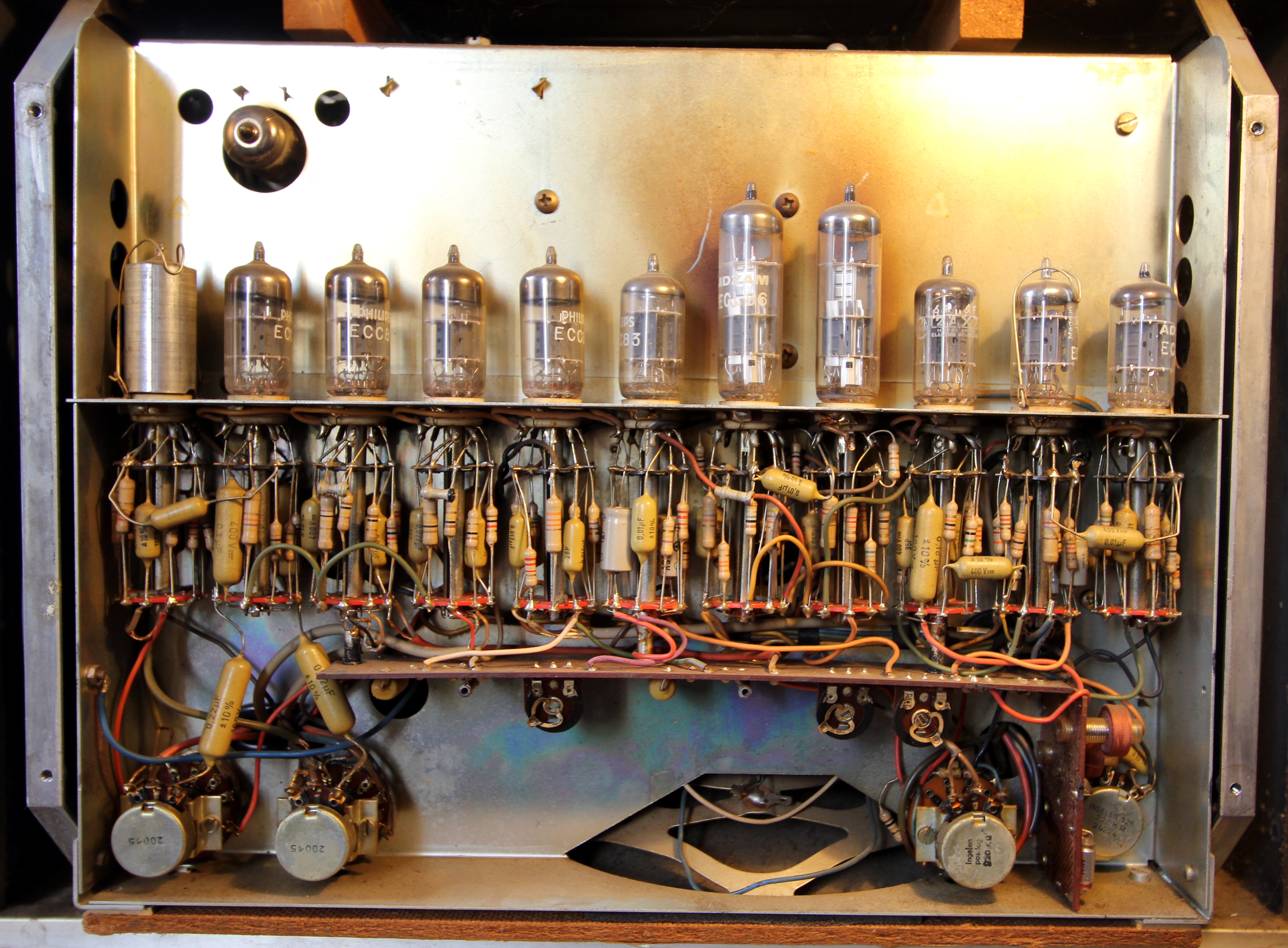
The main problem one may encounter when servicing these machines is finding replacement vacuum tubes. If you are lucky, you may find some new spares from old stock. However, often used vacuum tubes are offered for sale. Never buy nor use these as even if they still work, most certainly they do not work after the original specs. Moreover, vacuum tube testers have long vanished and even if you could dig one up, it would also be a vacuum tube instrument in need of servicing itself... Here is a picture of the vacuum tubes as found in the G36, a machine produced in 1964 (serial number 75027):
If the tape reproduction fails and no replacement components can be traced, you are left with the option to build a new playback amp. By using modern op-amps, the sound can be greatly improved over the original at the detriment of 'warm' vacuum tube sound. Here is a tested circuit, taken from an application note for the OPA27/37 operational amplifiers by Burr Brown:
If you find the use of a dual power supply objectionable or impractical, you could consider using the somewhat older LM387 dual audio op-amp in a circuit like this:
The values for Rx and Cx depend on the tape head characteristics. They should be copied from the original values found in the machine to be repaired. In magnitude order values for Rx -if present- in the range 10k to 47k and 100pF to 1.5nF for Cx are common. The result of this replacement -if performed with proper care given to wiring and component quality- will exceed by far that of the original circuit. If you want an IEC correction network (this correction was the standard for all European recording work on analog tape), the following circuit can be used:
Note that in the IEC standard, there is no bass boost below 50Hz in the circuit and the roll off for the high frequencies is at 4500Hz instead of 3150Hz in NAB networks.
If a rectifier tube is found to be broken, replace it with a modern high voltage semiconductor double diode (BYV32 for instance). The same applies to selenium rectifiers, which we would always replace as all old types do leak now. This modification will not alter the sound at all.
Here is a view on the bias oscillator from a G36, using an ECC83 double triode valve:
As the mechanical parts of this model are very sturdy and rarely fail, it's worth the effort to modify the entire machine for use as a high quality tape playback machine. Taking into account that it's unlikely anyone would want to use these machines in recording mode, limiting their functionality to playback only gives them a new life. Undertaking such a refurbishing involves removing all vacuum tubes. The output transformer for the monitoring amplifier (T853 in the circuit diagram) can be removed as well., We also advice to limit the recorder to a single speed only: the highest available (19 cm/s of 38 cm/s). This highly simplifies the wiring in the signal path and thus reduces hum and noise considerably. We performed the operation on a G36, series number 75027 dating from 1964. Measurement of the properties of the reproduction heads (Bogen) were:
- Inductance: nominal 540mH (left channel measurement: 519mH Q=6.74, , right channel: 569mH, Q= 6.38)
- DC-resistance: 268 Ohm
- Output signal at -3dB modulation: 4mV (taken from the data sheet and the circuit diagram)
- Load: 100pF across the terminals.
This became the new circuit:
The 4k7 multiturn trimpot should be adjusted such that the output voltage is at 0dB (775mV) for a 100% modulated tape using a 1kHz sine wave signal. The outputs of the circuit can be connected to the 'cathode follower' RCA jacks on the backside of the machine..A furher improvement is still possible: taking into account that tape heads are fundamentally differential devices (none of its terminals are internally grounded), we can take profit of a true differential amplifier, thus eliminating any induced hum and noise unrelated to the tape head signal. Here is a design example:
Obviously, hum picked up by the tape heads themselves, cannot be removed this way. Screening of the tapehead itself is the only remedy here. Note that if you only want to replace the reproduction part of the recorder, you can remove all valves numbered V7, V8, V9, V10 and V11. The saved space can be used for mounting the 15V power supply.
The dutch composer Dick Raaijmakers, certainly one of the first to consider the tape recorder as a tool for music production, early in his career, modified the predecessor of the Revox G36, the F36, with some extra heads, to make loops and delays possible:
This machine is on display now in a museum in The Hague (Netherlands).
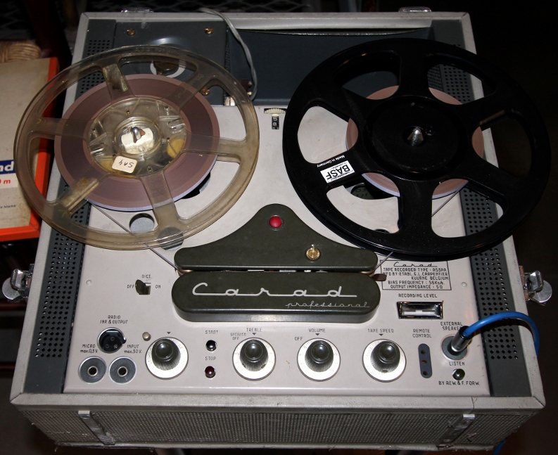
Carad models R62,R53, R59
Vacuum tube full track mono machines produced in Flanders (Kuurne) between 1955 and 1971. The later models using transistor technology and stereo. These later models were rarely seen used in live performance however. The older full track machines are worth to be preserved, as long as the tape heads are not worn. They were used by composers such as Henry Pousseur, Lucien Goethals, Louis De Meester and Norbert Rosseau. Here is one:
At the time of this writing, it is still in full working condition. Note that the bias frequency used on these machines is 56 kHz, so much lower than the 70 kHz used by the Revox G36 series.
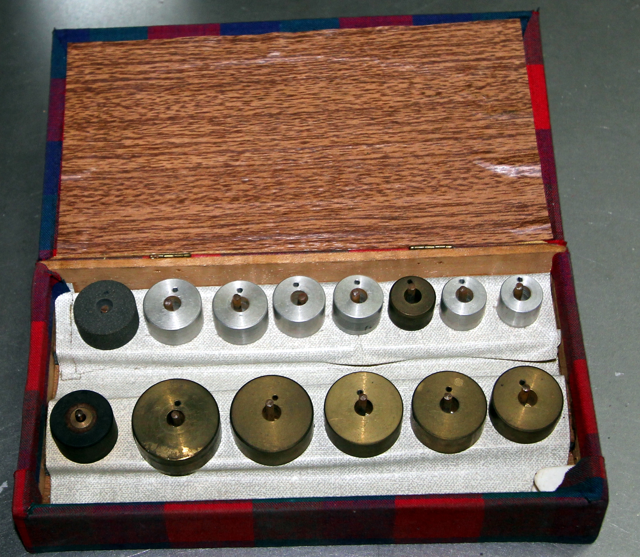
Truvox taperecorder
We ran into this type as it was in use in the private studio of my composition teacher, Norbert Rosseau. It's a mono half track machine with three heads and three motors with the odd property that it runs the tape from right to left... a British make, indeed. To make precise pitch transposition possible Norbert Rosseau had a set of alternative capstan wheels turned for him on a precision lathe. They run up in equal temperament chromatic steps. Here is a picture of the complete set:
When used to record a sound, on playback with the normal capstan, all sorts of chromatic pitch shifts became possible. Obviously, this way of transposing pitch, also affects duration. If pitch had to be preserved, a machine with rotary heads was required (Springer machine).
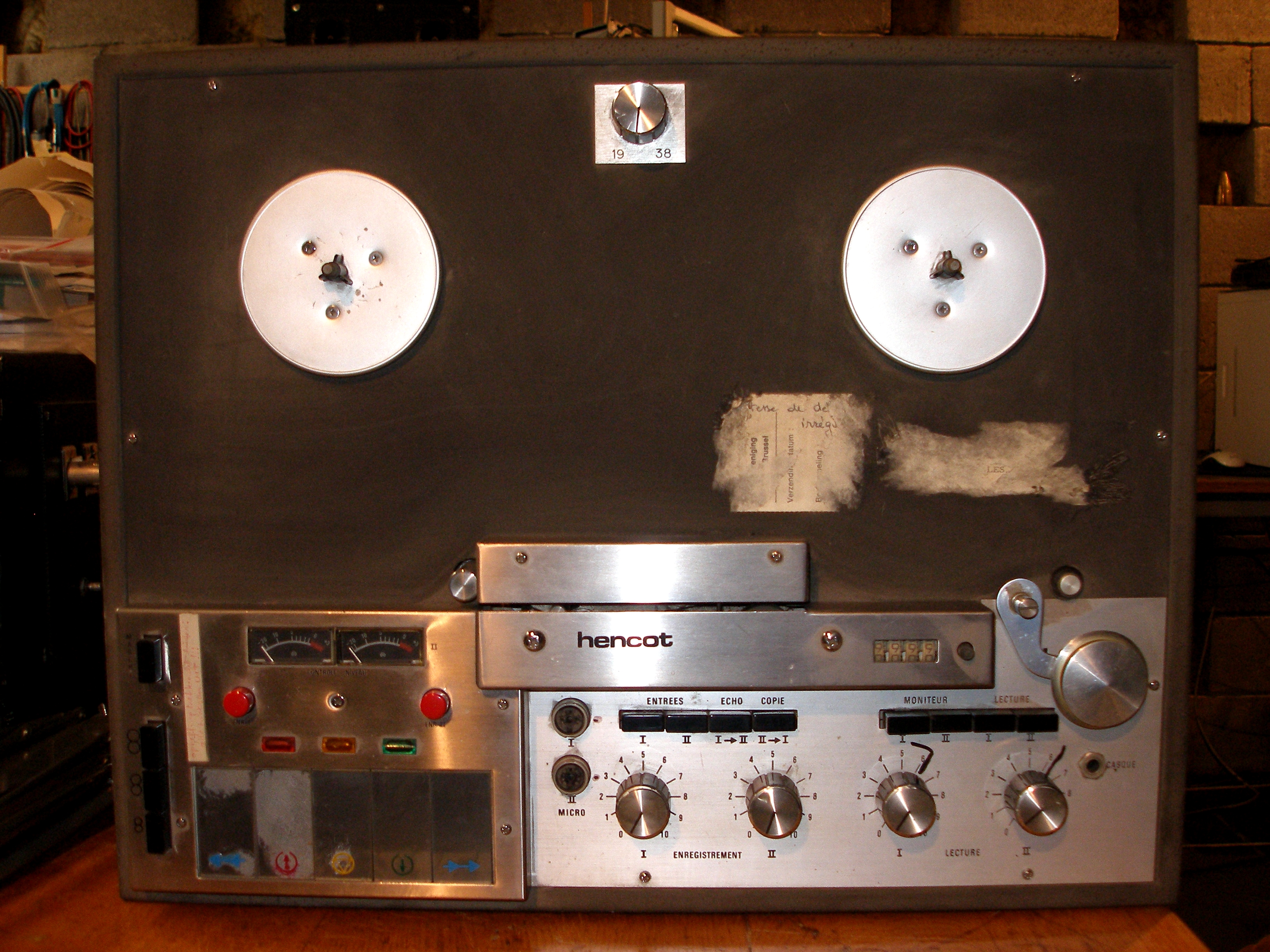
Hencot reel to reel tape recorder (1974):
Revox B77 and PR99 models:
These are improved versions over the A77 model. A feature of these machines was that it was possible to control motor speed continuously, thus giving rise to manifold new musical possibilities. Nevertheless they were considered to be less sturdy than the A77.
By the beginning of the ninetees we saw a gradual disappearing of the reel to reel tape recorder on stage. Pieces for musicians and tape were more and more making use of the much smaller cassette recorder. However none of these compact casette machines have ever been produced equaling the performance of the reel to reel machines. The signal noise ratio was at least 12dB worse and distortion was also much higher. To overcome this, the machines often were equiped with Dolby noise reduction systems and/or had to use special magnetic tapes (so called 'metal' tape). However, this caused quite some compatibility issues when using a different machine for playback of the cassettes. The favorite high quality brands and types used were:
Nakamichi 550:
Presumably the best cassette deck ever produced.
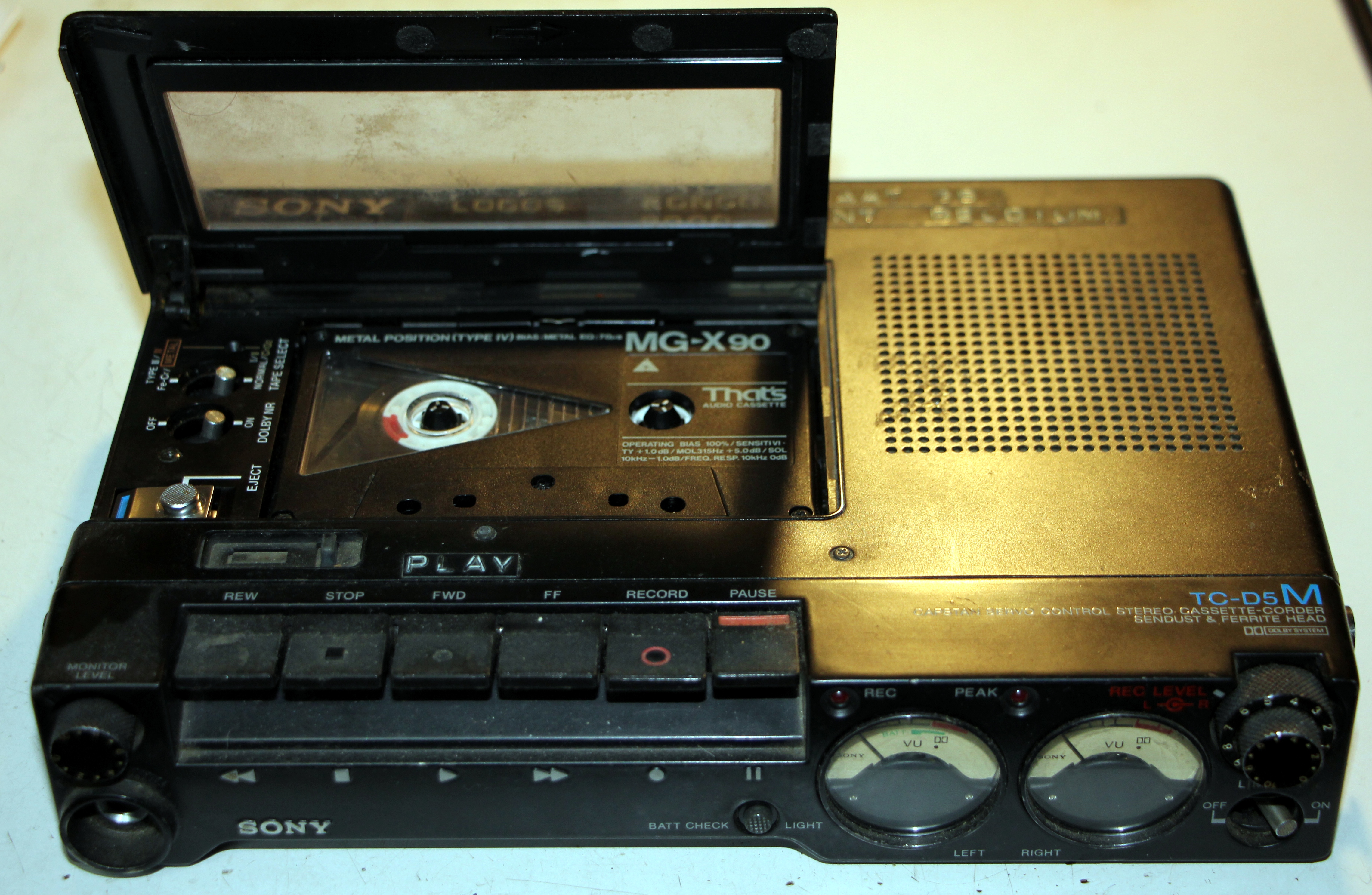
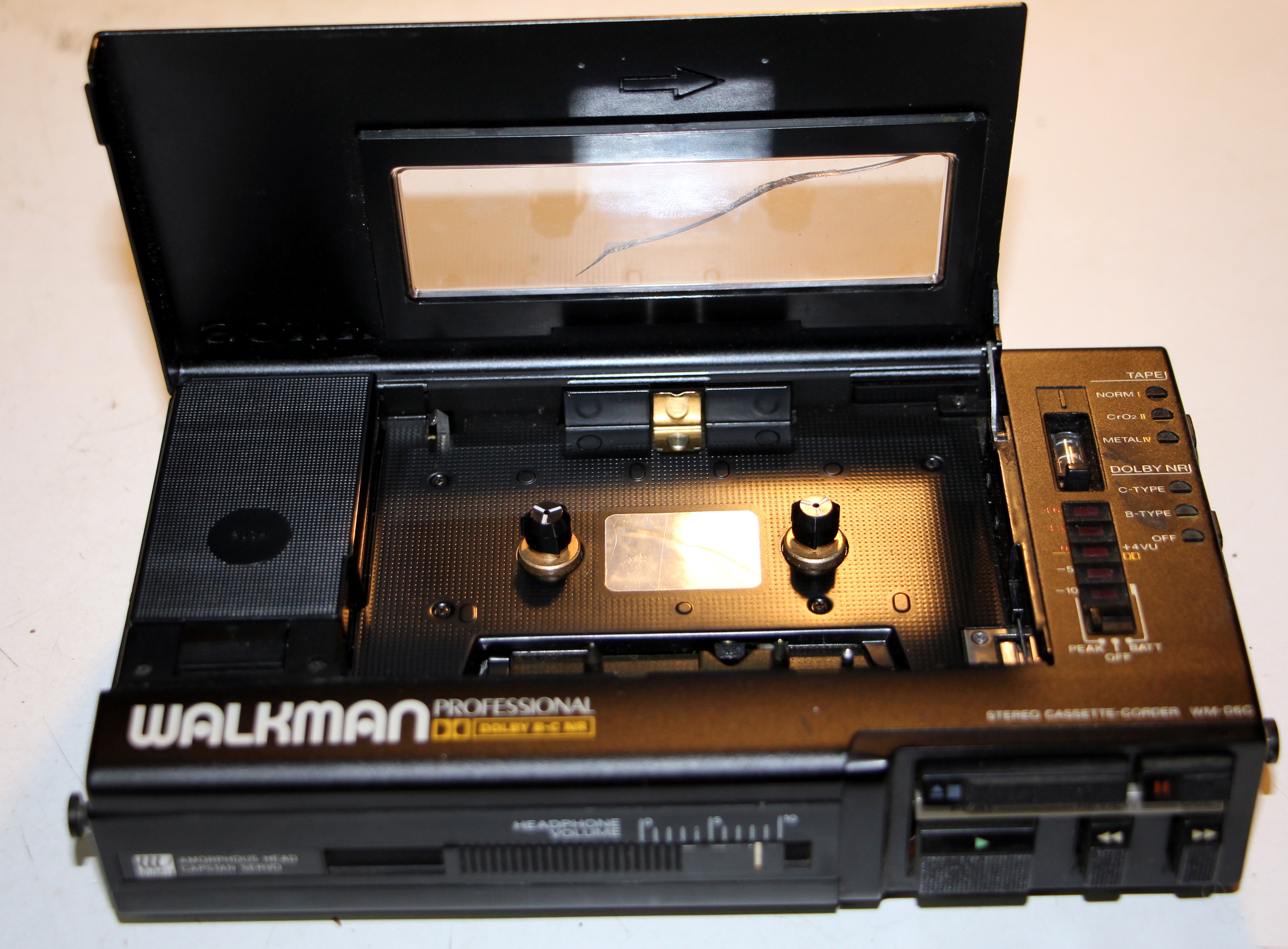
Sony TCD10
Sony WMD5 series
Although been widely used, their importance in live performance is minimal and there is no reason to call in casette recorders if it comes to historical performance practice. Moreover, even if anyone wanted to use them again, the problems of maintenance are nearly unsurmountable. We have quite a collection of these machines, but all of their potentiometers (exception made for the Nakamichi) crackle and cause a lot of noise. Replacement parts are absolutely unobtainable and standard parts do not fit the housing. A replacement with computer audio or CD seems appropriate and legitimate here. After all, there is little 'creative' of 'performing' you could really do with these machines: no tape loops, no separate recording and playback heads, no tape speed control, tiny and fragile connectors, no way to cue the tape with any degree of precision...
Contraptions using tape recorder derived technology:Loose tape heads with preamplifiers
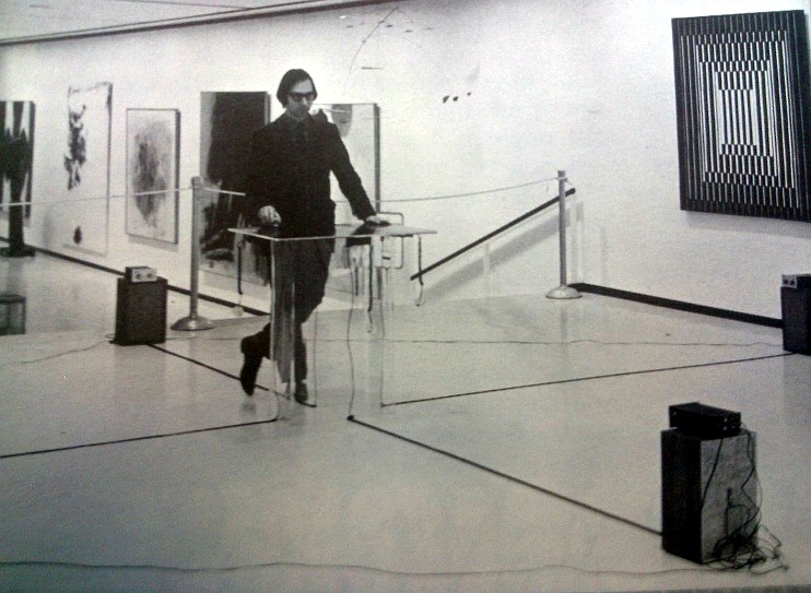
In one of the first issues of the legendary 'Source' magazine, one page appeared consisting of a square layer of magnetic foil. This was to be used as score material by reading it with a spare tape recorder head. Instructions were given in the score. The composer was Jon Hassell. Here is a picture of the composer performing the piece:
Mounted tape heads:
Dick Raaijmakers: 'Der Leiermann'
For this piece a machine is to be made allowing you to playback the prerecorded tape (containing a recording of the famous Schubert lied with the same title) with a handcrank driving the capstan. If any performer now would be willing to undertake a reconstruction of this piece, reconstruction of a copy of the original machine is a requirement.
Godfried-Willem Raes: 'Manipulofoon'
The NAB corrected circuit board looks like:
Two full-track tape heads are used and the device has two separate audio output channels. For playing it should be mounted on a camera tripod. Further documentation can be found here.
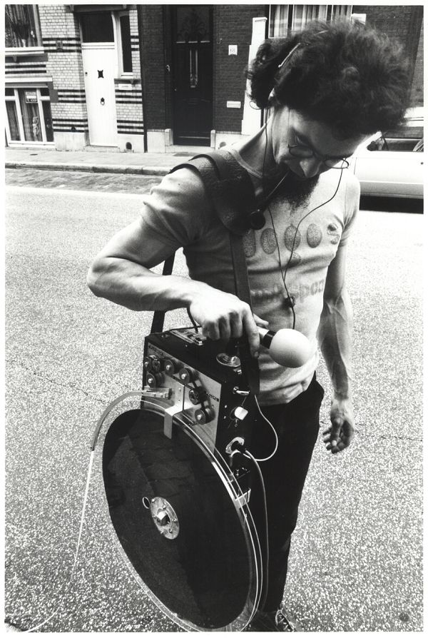
Michel Waisvisz
Michel Waisvisz' device is very similar, but he used a single tape head, megaphone loudspeakers and battery operated amplifiers.
Recorders without motor:
Godfried-Willem Raes: 'SoundTrack machine
SoundTracker #1:
SoundTracker #2:
More documentation on these projects can be found here.
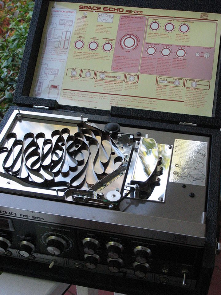
Tape echo and looping machines
These were amongst others produced by Roland around 1974. Here is a picture of their RE-201 model 'Space Echo':
Springer machine
This was a machine wherein a rotating playback head was used, a bit like in the much later developed video recorders. When the head was made to move against the movement of the tape, the pitch of the sound material could be transposed upwards without changing the duration of the recorded material. If the head was made to rotate in the direction of the tape, at the other hand, the pitch could be transposed downwards. No matter how beautifull a machine at first sight, it never worked without some flaws: glitches and dropouts. We donated our springer machine a few years ago to the MIM museum in Brussels.
As -as far as we know- Springer machines found no use in live electronics and performances, we see no reason for treating them in any depth here. Since the advent of computers powerfull enough to handle audio in real-time, the function of these machines can very easily (and much better...) be replaced with software: pitch-shifting and time stretching are standard components in just about any modern audio editing program.
Case studies and reports with regard to real time performances using tape recorders:
Brian Ferneyhough, 'Time and Motion Study II' for cello and electronics.
A historical reconstruction of this composition was realised and presented at De Bijloke, may 9th of 2015 with cellist Benjamin Glorieux. Tape operators were Maarten Craeynest, Pieter Matthynssens and Laura Maes.
For this piece four reel to reel tape recorders are required as well as ringmodulators and volume controls. We provided all legacy equipment required for a historical performance.
Karlheinz Stockhausen: 'Solo mit Rueckkopplung'
This is one of these pieces that nowadays is perfectly realizable using digital technology. Yet, if the tape loops required after the score are dismissed, the piece also looses all its charms. We have seen it performed my times since the late sixties -the Dutch oboist Evert Van Tright was a notorious performer of the piece- and everytime it appeared to be quite a challenge to get the tape running smooth enough. Most of the time there was quite some jitter and a couple of times, we had to cope with tape fracture. Replaced with a simple computer patch, the piece becomes almost trivial and even seems to collapse.
Pauline Oliveros
Some of her compositions involving tape recorders, loops and delays are described in her collected writing 1963-1980, published under the title 'Software for People' (Smith Publications, Baltimore, 1984, ISBN 0-914162-59-4). Here are her descriptions of the different set-ups used:
Here, as in the case of the Stockhausen piece, we think that the physical set up fundamentally adds to the rhetoric of the piece. It also makes the piece visually understandable. Only for recorded versions, a digital alternative sounds acceptable, but one could question the reason for doing this, as decent recordings made by the composer herself are available.
Godfried-Willem Raes 'FortePiano'
For this piece a single 15ips (38 cm/s) tape recorder is used as a delay machine. The short delay is caused by the physical distance between recording and reproducing heads.
Jerome Noetinger and Lionel Marchetti performing with revox taperecorders (link to a Vimeo video from the STEIM archives). and loops:
Steve Montague 'Ambush'
Notes:
(1)
Credits & Acknowledgments:
Part of the research results presented here where obtained thanks to the support of the Orpheus Institute. (ORCIM)
Thanks to the Logos Foundation, up to 2015 funded by the Flemish Government, where my instrument building workshop and electronic research lab are based.
Manufacturers of devices treated here:
Bibliographical references:Austin, Larry & Kahn, Douglas, 'Source, music of the avant-garde, 1966-1973', University of California Press, 2011)
Briggs, G.A. "Sound Reproduction", ed. Wharfedale Wireless Works, Bradford (1953)
Jansen, Arian "A universal NAB to IEC playback equalisation converter for reel to reel recorders' (2008)
Julander, E "Guide to Radio Technique', ed. Philips Technical Library, Eindhoven (1965)
Lucier, Alvin "Music 109, notes on experimental music", ed. Wesleyan University Press (2012)
Moir, James 'High Quality sound reproduction', ed.Chapman & Hall, London 1958.
Morrison, Robert K. 'Standard Tape Manual' (Kensington, California, no date)
Oliveros, Pauline "Software for People",Baltimore, 1984.
Richter, Heinz "Elektroakustik fuer Alle", ed. Franckh'sche Verlagshandlung, Stuttgart,1954
Strange, Allan "Electronic Music"
This article is part of a research project on Experimental Legacy financed in part by the Orpheus Institute in Ghent.
www.orpheusinstituut.be
First public appearance on internet: as yet undisclosed.
Last revision: January 6, 2023