|
<PlayerPiano>
Pedal robot |
|
Godfried-Willem RAES
1994-2016 |
|
<PlayerPiano>
Pedal robot |
|
Godfried-Willem RAES
1994-2016 |
Concert pianos have three pedals. The left one, called 'una corda' pedal, shifts the hammers (as well as the entire keyboard mechanism) a bit to the right such that 1 or 2 strings only get to sound on the notes that have 2 or 3-unison strings. This pedal is very hard to automate, since it would require the movement of the entire vorsetzer. This mechanism rests with its full weigth of around 35kg on the fixed wooden blocks on the left and right end of the keyboard. If we were to let it move with the keyboard itself, the piano mechanism would have to carry all this extra mass, a prohibitive proposal. Making the key tangents wider such that the keys could move under them would constitute an alternative, but the friction induced by 88 key with tangents would equally well lead to a prohibitive proposal.
The middle pedal (normally always called the third pedal, for historically it was only invented after the introduction of the left and right pedal) keeps the dampers up of the keys that are depressed on that moment. There is no musical reason to implement this on a piano robot, since the same function can easily be implemented with the key control. Even silent depressing of keys and holding them down is possible. Since our vorsetzers have 88 fingers, this does not impose any further penalty to virtuosic playing.
The right and second pedal is the sustain pedal. It lifts all dampers from the strings. It is in no way a simple on/off switch, as sensitive players use a lot of pressure and speed nuances and variations in their piano playing. Thus it seemed essential to add a good implementation of an automatic pedaling mechanism if our robot pianos want to cope with capabilities of human performers.
In our design for a pedal mechanism we were after a full and musically sound implementation of this second pedal. By design we wanted to stick to the concept of the Vorsetzer, implying that no changes to the piano itself should be required. The pedal playing robot should be a pure external activator of the existing and unmodified piano pedal.
Technical Description Player Piano Pedal
The force required to push the right piano pedal down is greatly dependent on the mechanical properties of the piano itself. Light actions require less than 30 Newton whereas on some pianos we measured a required force up to 60 Newton. On our own Kawai baby grand, 50 Newton was required. These forces were measured at a point 25 mm from the extreme edge of the pedal. Of course if the force is applied closer to the pivot point, required force will be proportionally larger. The usefull traject also greatly varies from piano brand to brand. Generally the traject, measured at the extreme end of the pedal does not exceed 50 mm. All this determines the choice of solenoid to be used to activate the pedal.
We went for a August Laukhuff solenoid specified for 55 Newton at 24V/ 1.41A. Its a big and heavy thing, but it provides smooth and silent action. It is designed as a pull magnet, but since the anchor sticks out at both ends, the action can be reversed, if we suspend the solenoid. With varying voltages between 11V and 25V applied to the solenoid the pedal comes gradually down. When 24V is suddenly applied, the action is too slow however for a musical use. Thus we decided to overdrive the solenoid and apply a (controllable) maximum pulse voltage to initiate the action in the range 33 to 66V.
As it comes to automation, we seem to require the following control parameters:
This is a whole lot more than what we find implemented on electronic keyboard instruments, where the sustain pedal is merely an on/off switch. It is also implemented under standard midi (controller 64) as a simple binary switch. Therefore a full implementation of a real world piano pedal cannot be realized if we stick strictly to the midi conventions. In our implementation, we use three controllers to set the characteristics of the pedaling. The standard controller for the pedal, nr., 64, is used with a data byte that steers the speed wherewith the pedal will come down, analogueos to the velo byte in midi note-on commands. The force of this attack can be preprogrammed with controller 65 and the force during the pedal down hold phase with controller 67. Finding good values for controllers 65 and 67 will be highly dependent on the actual piano used. If you set these controllers too high, you will have a lot of mechanical noise from the piano action. It they are too low, the action will be slow and sluggish. For a slow piano pedal release, controller 68 should be used. Controller 68 sets the release time in the range 11ms to 1400 ms. Understanding the principles behind the driving circuitry may be of some help to good use of the possibilities of the pedal:
As with many of our previous robots and automated instruments, here again we used a PIC microprocessor to implement all the requirements. Both PWM outputs are used to switch the two power mosfets. The possibility to use a sensor feedback mechanism to sense and control the behaviour of the pedal is still under consideration..
Improved electronic hardware in use since 2016 (Version 3):
 The left
part of this circuit finds a place in the power supply module designed for the
2016 model of the player piano. The rightside part of the circuit is still inside
the pedal assembly. Due to the quad optocoupler there is full galvanic isolation
between the pedal and the controller board. The optocoupler used is not particularly
fast, hence we kept the PWM base frequency at a modest 4kHz. Here is a detail
of the wiring for the 5-pole DIN connector between PS2016 module and the pedal
mechanism:
The left
part of this circuit finds a place in the power supply module designed for the
2016 model of the player piano. The rightside part of the circuit is still inside
the pedal assembly. Due to the quad optocoupler there is full galvanic isolation
between the pedal and the controller board. The optocoupler used is not particularly
fast, hence we kept the PWM base frequency at a modest 4kHz. Here is a detail
of the wiring for the 5-pole DIN connector between PS2016 module and the pedal
mechanism: 
As an extra feature two lights are mounted in the pedal robot The blue LED light is mapped on note 127 and the amber light on note 126. The lights can be made to flash if a note pressure command is sent via midi. The value of the pressure byte determines the flashing speed. A note off command will dim the light and stop the flashing. Note that we used low voltage P-channel power mosfets for the lights here!
The printed circuit board for the microcontroller part looks like this:
 And here is the
printed circuit board for the power mosfets and the quad optocoupler receiver
placed inside the piano pedal assembly:
And here is the
printed circuit board for the power mosfets and the quad optocoupler receiver
placed inside the piano pedal assembly:  The
somewhat weird design was caused by the fact that we had to design it for the
already existing welded construction that in an older version housed a very
different PCB. It's a bit cramped now and for new designs the PCB can be improved.
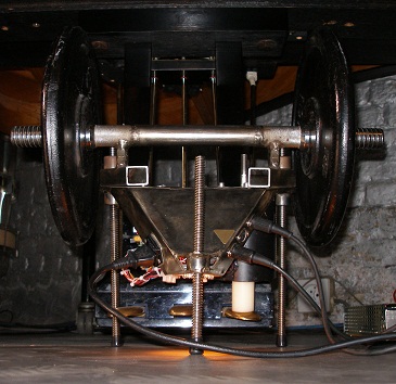
Here is a picture of the assembled board, mounted inside the pedal chassis:
The
somewhat weird design was caused by the fact that we had to design it for the
already existing welded construction that in an older version housed a very
different PCB. It's a bit cramped now and for new designs the PCB can be improved.
Here is a picture of the assembled board, mounted inside the pedal chassis: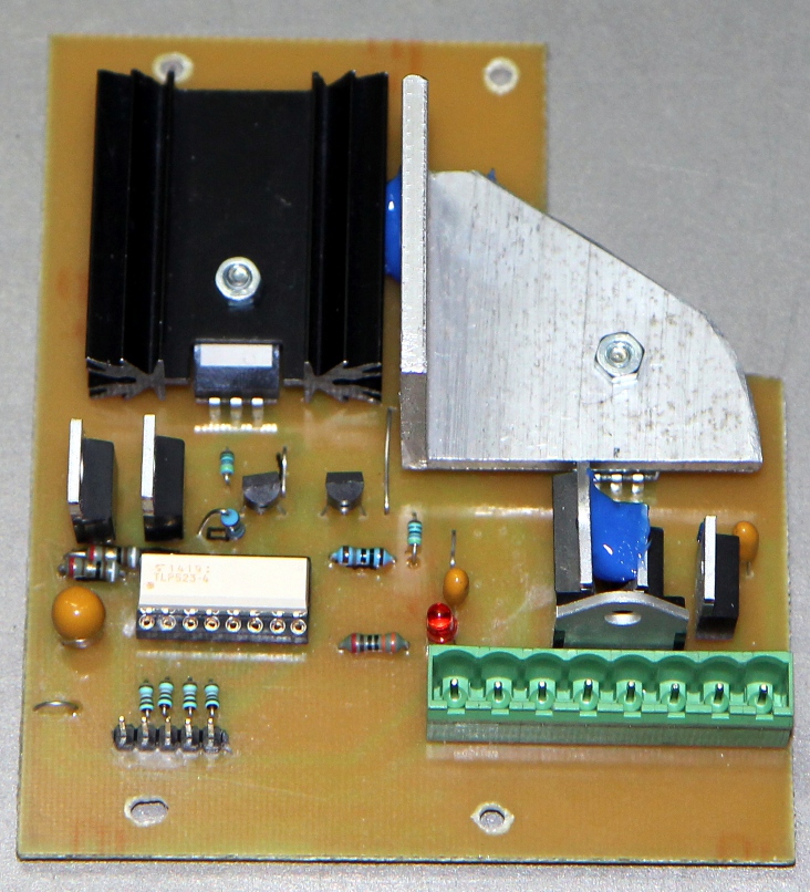 The
white 16pin chip is the quad optocoupler. Note that the power mosfets are mounted
upside down on the heatsinks. This is in fact due to an error in the PCB design...
The
white 16pin chip is the quad optocoupler. Note that the power mosfets are mounted
upside down on the heatsinks. This is in fact due to an error in the PCB design...
The playing possibilities of this pedal by far surpass anything even the best human pianist could do. To achieve this result, however, a lot of time must be spend on adding all nuances to the MIDI files or to the composition software written to use the piano pedal.
Note for organisers:
the player pianos I and II as well as the pedal robot described on this page will always and only be operated by a qualified technician or musician from the Logos Foundation. So, the instruments will not be rented out on their own. (Dont even ask). The insurance value for these instruments is 17.000 € plus 1.500 € for the pedal module. The grand piano itself has always to be provided by the organiser. No modification on the piano itself is required. Placement of the instrument on the piano is absolutely harmless to the instrument. Note that the music requires the piano to be in top condition and well tuned.
Transportation of the robot is possible with any normal sized car. The case of the mechanism measures 1400mm x 200mm x 200mm. The control computer for player piano 1 is build into a 6 unit 19" rack. For <pp2>, version 2005, it is a much smaller module containing only the hefty power supply. It fits in a normal attache case. The module for the 2016 version is slightly larger.The Vorsetzer case is very heavy (47kg) and requires 2 people to be lifted up and carried. Installation on the piano takes less than five minutes. Placement of the pedal robot involves only a mechanical adjustment of the heigth of the pusher. The pedal module weigth is about 35kg. (10kg for the piano pedal robot itself, plus 25kg extra mass consisting of body building weights).
Please note the technical requirements with regard to the piano: 88 keys grand piano and a free flat space on the left and on the right side of the keyboard of at least 31mm. The height of these blocks should not extend higher then the level of the black keys on the keyboard.
Collaborators on the design and realization of the player piano pedal robot:
Midi Implementation table: see page on the player
piano itself.
Construction log for Player Piano Pedal Robot:
 The midi input
circuit including the optocoupler and the buffers (74HCT14) are placed on
a small board very close to the midi connectors. We provided 2 midi thru connectors
to allow easy connection in combination with the vorsetzer (our 2005 model,
<pp2>, has only a single midi in connector and no thru's of its own).
The power supply is discrete (the large transformer adds welcome weight in
this design) and without circuit board, whereas the PIC circuit resides on
a small PIC prototyping board. The connections (a single Weidmueller 8-pole
connector) are as depicted below:
The midi input
circuit including the optocoupler and the buffers (74HCT14) are placed on
a small board very close to the midi connectors. We provided 2 midi thru connectors
to allow easy connection in combination with the vorsetzer (our 2005 model,
<pp2>, has only a single midi in connector and no thru's of its own).
The power supply is discrete (the large transformer adds welcome weight in
this design) and without circuit board, whereas the PIC circuit resides on
a small PIC prototyping board. The connections (a single Weidmueller 8-pole
connector) are as depicted below: 
The current through the optocouplers was calculated to be 10mA..
Here is the version 3.1 firmware
for the pedal controller. Starting the design for the PCB inside the pedal
mechanism.
| (Terug) naar logos-projekten: projects.html
Back to logos projects |
Terug naar Logos' index-pagina
back to main index |
Naar Godfried-Willem Raes personal homepage...
back to Godfried's page |
Back to playerpiano pages
|
Naar katalogus instrumenten gebouwd
door Godfried-Willem Raes
back to catalogue of instruments by Godfried-Willem Raes |
Last update: 2017-08-05 by Godfried-Willem Raes
Maintenance notes and spare parts list
Transformer used: EREA 66TR160
Solenoid: August Laukhuff, Trakturmagnet 24V/ 1.51A - 55N
Pusher: Epramid stave, turned to size on the lathe.
Power MOSFET's: IRF1310NPBF (Vdss = 100V, Rds-on= 0.036 Ohm, Id = 42A, Ug=10V)
Power diodes: STTH30R06PI (fast, 30A, 1200V)
Quad opto-coupler: TLP523-4 Datasheet
Thread on the three set screws: 12 mm trapezoidal (TR12)
All constructional parts, including nuts and bolts, are stainless steel.
Weigths: Body Builders Weigths. (assortment from 5kg to 80 kg to accomodate the piano). The small ones are a donation by Luk Vaes. In the standard set up, two weights of each 10kg seem to suffice as a minimum.