<HybrLo>
a sub octave electroacoustic pipe organ using membrane driven resonator
pipes
Godfried-Willem RAES
V1.0: 2016
archive file
|
<HybrLo> a sub octave electroacoustic pipe organ using membrane driven resonator
pipes archive file |
<HybrLo>
As the results of the <Hybr> robot turned out
very positive, and after building the top octave extension <HybrHi>,
we decided to give it another extension into the very low range of notes. An
extension in the low range was already conceived after finishing <Hybr>
but due to the inherently large size of the pipes, we left the idea dormant
for a few years. But as the need became more and more urgent to get easier to
transport instruments in the very low register, we took up the idea again. Using
thin PVC pipe material makes indeed transportation a lot less problematic, even
though by necessity, it would have to be a rather large instrument. In order
to minimize size, we decided to limit the polyphony to 12 voices, and have each
pipe play either the low octave or the higher octaves. Thus octave doublings
becomes impossible by design. However, this way the ambitus of the instrument
becomes four octaves. It could even be further extended by adding the duodecimo's
and other harmonics. The inharmonicity of the pipes however becomes quite noticeable
and therefore we did not implement it.
. Learning some lessons from the <Hybr> design, here we strictly adhered
to the design rule stating that the ratio of pipe length to internal diameter
must be larger than 10. The pipes work acoustically as 1/4 lambda resonators..
As the required pipe lengths turned out too long to construct a transportable
instrument, we decided to crop them such that the total height of the instrument
stays smaller than 2 meters. So even fully mounted it will pass through a normal
door. We first calculated the ideal sizes for the lowest pipe and came to the
conclusion that this pipe ought to have a diameter of 300 mm if it should have
a resonance at the octave. Clearly, this would lead to a way too large instrument,
as even the diameter of the shortest pipe would become ca. 150 mm. However,
It would make a great instrument, as with such sizing the use of very powerful
drivers would become possible. If anybody wants to commission it, we are ready
to accept an order...
<HybrLo> was designed at a time the Logos Foundation was highly endangered,
as an advisory commission composed of complete idiots (however politically highly
correct...) issued a negative advice about our governmental funding. In such
an awkward context it became a priority to design the instrument such that it
could be build from recycled materials and merely components we had in stock.
Clearly this had severe repercussions on the visual appearance of this robot.
Sorry for that. Blame the conservative puritan leftists that oppose to real
experimental work in the arts for this.
As we used 16 bit microcontrollers (and not the 32 bit ARM controllers used
for <Hybr> and <Hybrhi>) the implementation of the controllers for
this instrument turned out a bit different. Some controllers found on the other
instruments (vibrato and tremolo) were dropped here, as for such low frequencies
it didn't make much sense. However, in this instrument we thought about experimentally
inclined composers and provided in individual ADSR control and waveshape for
every single note. Thus the instrument can even be used to mimic percussion
instruments or pizzicato bass lines. For compatibility with the other instruments,
global controllers for these parameter are implemented as well. To make things
even easier for users, we implemented a small set of presets as well.
The 16-bit microprocessors in this robot are working at the upper limit of their capabilities. All the code is based on a multitude of fast interrupt handlers running at up to ultrasonic frequencies which by their very nature had to be handled in a hierarchical way. All wave processing makes use of PWM modulation, nine channels for each processor. This 'on the edge of processor possibilities' approach is not without musical consequences and in a way the robot in the end has somewhat of a more human behaviour: as the music gets faster and more complicated, it may give up on precision. It will not crash nor get out of tune, but as the number of controllers and key pressure commands send to it becomes very high, the enveloppes will tend to become a bit irregular and shaky.
Here is an overview of the complete circuitry:
Definitive pipes as made, tuned and measured:
| freq | 1/4 lambda | f0 | f1 | f2 | f3 | l/d | L | De | Di | SPL | Spkr | L1 | U-length | L2 | Le | |
| 22 |
29.135 | 2956 | 29 | 58 | 117 | 233 | 23.6 | 2879 | 125 | 119 | 89dB | GW-205/85 40 W | 1639.3 | 430 | 712,1 | - |
| 23 | 30.868 | 2790 | 31 | 61 | 122 | 244 | 22.32 | 2713 | 125 | 119 | 90dB | LPB130 Nokia 4 Ohm 25 W | 1528.6 | 430 | 856.6 | - |
| 24 | 32.703 | 2634 | 33 | 66 | 132 | 264 | 21.07 | 2557 | 125 | 119 | 90dB | LPB130 Nokia 4 Ohm 25 W | 1424.6 | 430 | 604.8 | - |
| 25 | 34.648 | 2486 | 35 | 70 | 140 | 280 | 22.83 | 2420 | 110 | 106 | 90dB | LPB128 4 Ohm 20 W | 1390.5 | 315 | 616.5 | - |
| 26 | 36.708 | 2346 | 37 | 74 | 148 | 296 | 21.51 | 2280 | 110 | 106 | 90dB | LPB130 Nokia 4 Ohm 25 W | 1300 | 315 | 572.5 | - |
| 27 | 38.890 | 2215 | 39 | 78 | 156 | 312 | 20.27 | 2149 | 110 | 106 | 90dB | BMW 4 Ohm 25 W | 1212.5 | 315 | 528.7 | - |
| 28 | 41.203 | 2090 | 41 | 82 | 164 | 328 | 20.90 | 2028 | 100 | 96 | 90dB | ITT LPB128 4 Ohm 25 W | 1133.6 | 310 | 489.3 | - |
| 29 | 43.653 | 1973 | 44 | 88 | 176 | 352 | 19.73 | 1911 | 100 | 96 | 90dB | LPB128 8 Ohm 20 W | 1150 | 316 | 250 | 195 (140+55) |
| 30 | 46.249 | 1862 | 46 | 92 | 184 | 368 | 18.62 | 1800 | 100 | 96 | 90dB | LPB130 4 Ohm 25 W | 1600 | - | - | 195 (140+55) |
| 31 | 48.999 | 1757 | 49 | 98 | 196 | 392 | 20.29 | 1705 | 90 | 84 | 92dB | LPB128 8 Ohm 20 W | 1575 | - | - | 130 |
| 32 | 51.913 | 1659 | 52 | 104 | 206 | 412 | 19.13 | 1607 | 90 | 84 | 93dB | ITT LPB120 8 Ohm 20 W | 1477 | - | - | 130 |
| 33 | 55.000 | 1566 | 55 | 110 | 220 | 440 | 18.02 | 1514 | 90 | 84 | 93dB | LPB128 8 Ohm 20 W | 1394 | - | - | 130 |
For the calculations the velocity of sound was taken as 344 m/s, for a temperature of 21 degrees Celsius. Note that with this mensure the cross section surfaces of the lowest and highest pipes relate to each other as 2:1. (11122 mm2 versus 6361 mm2). All speakers are used below their resonant frequency if the fundamental is sounded.
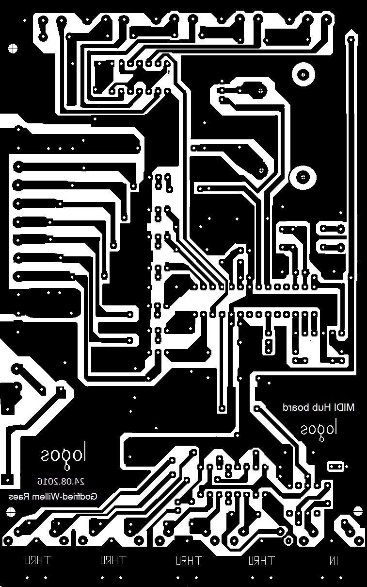
The electronic circuitry consists of a midihub board containing a MIDI parser,
and the controls for the lights. Next we have four tone-generator boards each
generating three notes. For these boards we used 16 bit PIC processors designed
for steering motors in three phases. Thus we could implement three channels
of independent pitch generation with full ADSR control on each board. This is
the circuit:
 The component
values for the note filters are different for each opamp. They were calculated
using an online filter calculator by Analog Devices. The -3dB frequency was
calculated for 8-times the fundamental frequency. The -12dB point at twice this
frequency. The envelope filters are dimensioned for a cut off frequency at 40Hz.
All resistors are 1% precision, but for the capacitors we had to live with 5%
due to unavailability of precision capacitors on the market. (For inductors,
the situation is even worse, as common tolerances are no better than 20%). In
the circuit drawing given above, the values shown are for the notes 22, 23 and
24. The source code for these four boards can be found under these links:
The component
values for the note filters are different for each opamp. They were calculated
using an online filter calculator by Analog Devices. The -3dB frequency was
calculated for 8-times the fundamental frequency. The -12dB point at twice this
frequency. The envelope filters are dimensioned for a cut off frequency at 40Hz.
All resistors are 1% precision, but for the capacitors we had to live with 5%
due to unavailability of precision capacitors on the market. (For inductors,
the situation is even worse, as common tolerances are no better than 20%). In
the circuit drawing given above, the values shown are for the notes 22, 23 and
24. The source code for these four boards can be found under these links:
The hex-dumps are available as well. These can be uploaded in the microcontrollers using MPLAB and a PICkit-3 programmer (Microchip). If you really want to get some understanding as to how this instrument works, we strongly advise you to pay the effort to study the source code. We did an effort to document it pretty well. Notwithstanding this, a reading of the Microchip programmers manual may be required before you attempt to change anything in the code.
| Hybrlo_22_24.hex | Hybrlo_25_27.hex | Hybrlo_28_30.hex | HybrLo_31_33.hex |
As we wanted quite a powerful sound we used >20 W loudspeakers to drive the PVC tubes. We used recycled 135 mm chassis speakers as commonly used in quality cars produced between 1980 and 1990. (hence the 4 Ohm impedance of most speakers). This made a twelve channel audio amplifier a requirement. We succeeded in designing these 12 channels on a single Eurocard board, cut in two halves. We used six TDA7264 stereo amplifier chips rated for 2 x 22 Watt each. Note that we are using all speaker drivers at frequencies below their resonant frequency. There is a risk of overloading the speakers, not because of too much electrical power but rather due to excessive mechanical excursion of the 110 mm cones at resonance with the air columns. At the one hand, using speakers below their resonant frequency lowers their efficiency a lot, but then at the other hand, using them with a tuned resonator makes up for the loss in efficiency. To finish it all up, we had to design the required power supply circuits as well. For the amplifiers we used a classical analog power supply with a 225 Watt toroidal transformer (2x 12 V). All amplifiers are mounted on a common heatsink. Note that the heatsink carries the -15 V power and is not insulated from ground! In order to limit power consumption and heat developed on the heatsinks, users are advised to always use the power off controller (#66) when the instrument is not playing. This fully mutes all amplifiers without really turning the power off.
Midi implementation and mapping:
Midi channel: 8 (counting 0-15) [same channel as <Hybr> such that it
can use a same track in sequencer software and be treated as a single instrument.]
Note Off: notes 22 to 69, note release implemented.
Note On: notes 22 to 69, velo implemented.
Lights:
The lights are mapped on the note range 0 to 3. The velocity byte steers the flashing speed. With velo=127, the lights will be steady ON. Flashing speed can be modulated with the key pressure command.
Controllers:
| number | function | default setting / remarks | |
| #1 | Frequency jitter | noisyness of the sound. 0 by default | |
| #7 | Global sustain level | this controller cannot be used to change volume for sounding notes. | overrides individual settings |
| #15 | Global waveshape | 127 (corresponding to 50% duty cycle wave) | overrides key pressure settings for individual notes |
| #17 | Global attack time | 0-206 ms | |
| #18 | Global decay time | 0-206 ms | |
| #19 | Global release time | 0-512 ms | |
| #20 | Tuning | Global tuning (range, a quartertone up or down). Default value 64 for A= 440 Hz (*) | not yet implemented |
| #21 | attack time note 22 | applies to notes 22, 34, 46, 58 | 0-206 ms |
| #22 | decay time note 22 | id. | 0-206 ms |
| #23 | release time note 22 | id. | 0-512 ms |
| #24 | attack time note 23 | applies to notes 23, 35, 47, 59 | 0-206 ms |
| #25 | decay time note 23 | id. | 0-206 ms |
| #26 | release time note 23 | id. | 0-512 ms |
| #27 | attack time note 24 | applies to notes 24, 36, 48, 60 | 0-206 ms |
| #28 | decay time note 24 | id. | 0-206 ms |
| #29 | release time note 24 | id. | 0-512 ms |
| #30 | flashing speed lights | Sets the flashing speed for all implemented lights. (notes 0 - 3) | |
| #31 | attack time note 25 | applies to notes 25, 37, 49, 61 | 0-206 ms |
| #32 | decay time note 25 | id | 0-206 ms |
| #33 | release time note 25 | id | 0-512 ms |
| #34 | attack time note 26 | applies to notes 26, 38, 50, 62 | 0-206 ms |
| #35 | decay time note 26 | id. | 0-206 ms |
| #36 | release time note 26 | id. | 0-512 ms |
| #37 | attack time note 27 | applies to notes 27, 39, 51, 63 | 0-206 ms |
| #38 | decay time note 27 | id. | 0-206 ms |
| #39 | release time note 27 | id. | 0-512 ms |
| #41 | attack time note 28 | applies to notes 28, 40, 52, 64 | 0-206 ms |
| #42 | decay time note 28 | id. | 0-206 ms |
| #43 | release time note 28 | id. | 0-512 ms |
| #44 | attack time note 29 | applies to notes 29, 41, 53, 65 | 0-206 ms |
| #45 | decay time note 29 | id. | 0-206 ms |
| #46 | release time note 29 | id. | 0-512 ms |
| #47 | attack time note 30 | applies to notes 30, 42, 54, 66 | 0-206 ms |
| #48 | decay time note 30 | id. | 0-206 ms |
| #49 | release time note 30 | id. | 0-512 ms |
| #51 | attack time note 31 | applies to notes 31, 43, 55, 67 | 0-206 ms |
| #52 | decay time note 31 | id. | 0-206 ms |
| #53 | release time note 31 | id. | 0-512 ms |
| #54 | attack time note 32 | applies to notes 32, 44, 56, 68 | 0-206 ms |
| #55 | decay time note 32 | id. | 0-206 ms |
| #56 | release time note 32 | id. | 0-512 ms |
| #57 | attack time note 33 | applies to notes 33, 45, 57, 69 | 0-206 ms |
| #58 | decay time note 33 | id. | 0-206 ms |
| #59 | release time note 33 | id. | 0-512 ms |
| #66 | power on / off | power off resets all controllers to default values. It also mutes the amplifiers | |
| #70 | sustain level note 22 | this controller can be used to steer volume during the sustain phase | applies to all Bb's |
| #71 | sustain level note 23 | this controller can be used to steer volume during the sustain phase | applies to all B's |
| #72 | sustain level note 24 | this controller can be used to steer volume during the sustain phase | applies to all C's |
| #73 | sustain level note 25 | this controller can be used to steer volume during the sustain phase |
applies to all C#'s |
| #74 | sustain level note 26 | this controller can be used to steer volume during the sustain phase | applies to all D's |
| #75 | sustain level note 27 | this controller can be used to steer volume during the sustain phase | applies to all Eb's |
| #76 | sustain level note 28 | this controller can be used to steer volume during the sustain phase | applies to all E's |
| #77 | sustain level note 29 | this controller can be used to steer volume during the sustain phase | applies to all F's |
| #78 | sustain level note 30 | this controller can be used to steer volume during the sustain phase | applies to all F#'s |
| #79 | sustain level note 31 | this controller can be used to steer volume during the sustain phase | applies to all G's |
| #80 | sustain level note 32 | this controller can be used to steer volume during the sustain phase | applies to all G#'s |
| #81 | sustain level note 33 | this controller can be used to steer volume during the sustain phase | applies to all A's |
| #90 | highest note limit | this controller can be used to limit the ambitus. The parameter is the highest note limit. | 22-69, default value 69 |
| #123 | all notes off | silences all notes but leaves controllers unaffected. |
If <HybrLo> is replacing <Bourdonola> in existing midi files, setting controller #90 to 62 will do. If it is used as a mere bass extension of <Hybr>, the controller could be set to 33.
(*) If the tuning is set much different from 440Hz, the overall amplitudes will be affected, unless tuning follows the changes of resonance frequencies as a result of temperature changes. The range is a quartertone up or down. Parameter value 64 equals A=440Hz)
To understand the different parameters and controllers available in this robot, a close look at the following graph might help:
 All levels are
scaled on a log scale selectable with controller #100. Followings scales are
implemented: 20dB, 30dB, 40dB, 50dB, 60dB. .
All levels are
scaled on a log scale selectable with controller #100. Followings scales are
implemented: 20dB, 30dB, 40dB, 50dB, 60dB. .
Key pressure is implemented for all notes in the ambitus of the instrument and used to modify the waveshape of the drive signal. By default key pressure it set to 127, corresponding to a 50% duty cycle wave. Key pressure commands can be sent at all times and do not require the note(s) they refer to, to be sounding. Key pressure commands are sticky: they are not reset with a note-off. Power off (ctrl.#66) will reset all settings to 127. The waveshape in use can also be globally controlled with controller #15. For the lights (mapped on notes 0 to 3) key pressure commands change the flashing speed for the lights that are turned on.
Channel aftertouch and pitch bend are not implemented on <Hybrlo>
Program Change: This command can be used to select a few different controller presets.
| Prog.# | name | remarks |
| 0 | default | optimum velocity values: 64 |
| 1 | plucked | ideal velocityvalues: 100 |
| 2 | nasal slow | velocities < 80 |
| 3 | organ | velocities @ 40, for a sound similar to <Bourdonola> |
| 4 | sharp | velocity is pretty irrelevant here |
Note that sending program change commands whilst notes are playing, can lead to unpredictable results at times. So this should be avoided. Sending an all-notes-off command followed by the program change command for the selected preset will allways work.
All level related controllers follow a logarithmic scaling from 0dB to -60dB:
As the processor used here has 16 bit PWM resolution, the 0dB reference corresponds to 2^16. Note that we use output voltage units (VU) here and not sound pressure levels according to a dBA scale. .
Music composed for <HybrLo>:
Godfried-Willem Raes 'Bottom Boot' , a once only namuda performance for an
unfinished HybrLo robot (15.09.2016, premiered by Emilie De Vlam and the author)
Here is an MP3 of this piece...
Kristof Lauwers, 'Study #20 for HybrLo' (2016)
Godfried-Willem Raes 'Lithos' (act1 in Technofaustus) with a special interactive
part for HybrLo.
Godfried-Willem Raes 'Namuda
Study #61: Family Completed'
| Back to Logos-Projects page : projects.html | Back to Main Logos page:index.html | To Godfried-Willem Raes personal homepage... | To Instrument catalogue |  |
Construction diary:
01/07.2016-16.08.2016: Study of the PIC 24EP128MC202 microprocessor. We will
use this type to generate 3 notes and 3 independent ADSR's. So for a 12 note
instrument, we could have enough with 4 boards. Comments on the firmware development
can be found in the header of the sourcecode files. For code development we
are using the Proton24 compiler and a PicKit3 programmer/debugger.
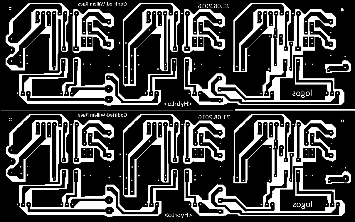
20.08.2016: Circuit and PCB designed for the 12-channel audio amplifier to drive
the speakers. The power supply for all these amps together should be rated +/-
15V - 8A. (120 VA should be enough). Here is the PCB:  The chip amplifier used on this board is TDA7264. There is a separate volume
potentiometer for each channel (Bourns 10k log). Amplifier gain for each amp
is 30dB. We provided in a muting input for all amplifiers together.
The chip amplifier used on this board is TDA7264. There is a separate volume
potentiometer for each channel (Bourns 10k log). Amplifier gain for each amp
is 30dB. We provided in a muting input for all amplifiers together.
21.08.2016: 12-channel power amp PCB finished: etched, drilled and soldered,
apart for some missing components that we had to order. Test and evaluation
board etched for a 3-channel synth using LC filters. The final version to be
used for HybrLo ought to have active filters though. Start design for the PCB
holding the tone generators.
22.08.2016: Further soldering work on the amp- and test/evaluation board. Test
board using LC filters finished. Results evaluated: we have excessive noise
stemming from the ADSR channel. First of all, the PWM should be disabled at
the end of the release phase of a note. Second: we have to recalculate the LF
filters with the actual values soldered in place. The eternal problem here is
the impossibility to get precision capacitors in the range 1uF to 47uF... However,
the ADSR implementation seems to perform well. There seems to be no way beyond
the use of active filters.
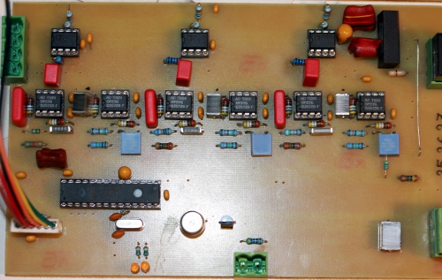
23.08.2016: Test and evaluation board finished. Signal noise ratio is not too
great with ca. -40dB. Here is the circuit drawing with measurement results:
 The noise at
the output stems from the AD633 multiplier. The noise level remains the same
with the inputs shorted. Here is a picture of the finished board:
The noise at
the output stems from the AD633 multiplier. The noise level remains the same
with the inputs shorted. Here is a picture of the finished board: 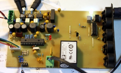 There
are better multipliers on the market, but they are a lot more expensive... This
is a scope image of the audio output on two channels, with ADSR applied:
There
are better multipliers on the market, but they are a lot more expensive... This
is a scope image of the audio output on two channels, with ADSR applied:  Missing components soldered on the 12-channel amplifier board.
24.08.2016: First working version for the firmware ready and tested. This code
serves notes 22, 23, 24 and their octaves 34, 35, 36. Continued work on the
PCB design for these boards. The active filter components can be calculated
with the on-line utility made available by Analog Devices. OP27 low noise precision
opamps will be used for these filters.
25.08.2016: Measurements and experiments carried out to make a good sounding
pipe resonator for the lowest note (midi 22, or 29.13 Hz) using 125 mm diameter
sewer pipe. It would be a good idea to give the pipes a flared end.
26.08.2016:Test pipe made as follows: 1 straight tube 1440 mm , 1 elbow 200
mm, straight piece 70 mm, 1 elbow 200 mm, 1 straight length 969 mm, so total
pipe length becomes 2879 mm. Taking into account the end correction this gives
an acoustical length of 2956 Hz. The Q-factor of the tube is not very high,
making it quite difficult to find a very exact tuning. In any case this works
pretty well when driven with a 4 Ohm speaker at 29 Hz (Our tonegenerator has
a readout with a resolution of only 1 Hz...). If we stick to 135 mm chassis
loudspeakers, it looks like we will have all speakers in stock.
27.08.2016: PCB's for the midi hub board and a first Pic24 with active filters
board etched. First tests with components for note 22.
28.08.2016: Some corrections made on the PCB for the active filter board. PCB
etched, drilled and start soldering components. Running out of photosensitive
Eurocard PC boards, so new order placed at Farnell.
29.08.2016: All filter values calculated and optimized for low noise using the
online Analog Devices utility. Code for hub board v1.0 finished. Hybrlo channel
decided to be 8, so same as Hybr and HybrHi. If we want to avoid the note overlap,
we should use this robot on a different port. E96 series resistors are no common
place at Farnell... Many essential values are missing in their assortment. Decided
to use OP27 opamps for all the filters. OPA627 would be overkill taking into
account the noise produced by the multipliers...
30.08.2016: Further design of the instrument. Waiting for components from Farnell.
Test pipe made for note 23. Two tone generator boards finished now, with the
components for the active filters. PCB design for the next two boards improved:
the film capacitors take more space than we anticipated... The signal/noise
ratio appears to be a lot better than what we feared. 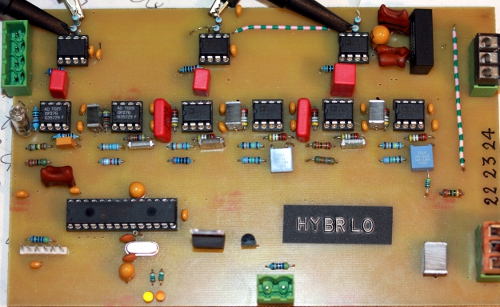
 Two more corrected PCB's
etched. Drilling will be for tomorrow...
Two more corrected PCB's
etched. Drilling will be for tomorrow...
31.08.2016: All drilling done. All components soldered in. The PCB's are all
ready for testing and programming now. Midi controllers to be implemented worked
out. There will be a wealth of them... We will implement key-pressure to modulate
the waveshape. Continued work on the firmware for the sound generator processors.
01.09.2016: GMT code written for testing all the boards. The test code is integrated
in the GMT-cockpit for <Hybr>. All note generator boards programmed and
tested with the oscilloscope. Source code and hex-dumps for the microcontrollers
uploaded to the Logos website. Start construction of the pipeholder -hardly
to be called a windchest in this case- from 25 mm thick PVC. The holes for the
pipes have to be sawn out with a jigsaw, as we do not have round saws large
enough. Start design of the chassis and the wheel base.
02.09.2016: Continuing work on the windchest. Missing PVC pipe material ordered.
Welding works on the chassis: stainless steel profiles 50x50x2 and 50x30x2.Wheels
mounted on the corners: these wheels have also horizontal rollers. Two wheels
have brakes. Running out of M10 x 100 bolts: up to MEA. Experiments with small
woofers (90 mm cones) recycled from Aciko small loudspeaker enclosures performed.
The cone excursion is too small and they produce a lot of distortion. Here are
some pictures of the works progres: 
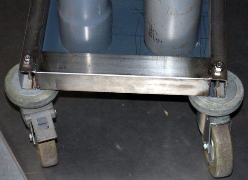

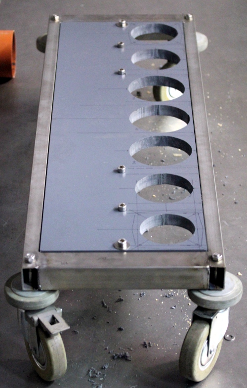 As you can see,
quite a way to go still.. It would be a good idea to have the pipework completely
removable. The amplifiers and their power supply ought to find a place underneath
the instrument. Front row with five pipes drawn out on the windchest. Drilling
and sawing is for tomorrow... Works in progress shown to Tim Deurinck, Xavier
Verhelst and Kristof Lauwers. No further disclosure yet.
As you can see,
quite a way to go still.. It would be a good idea to have the pipework completely
removable. The amplifiers and their power supply ought to find a place underneath
the instrument. Front row with five pipes drawn out on the windchest. Drilling
and sawing is for tomorrow... Works in progress shown to Tim Deurinck, Xavier
Verhelst and Kristof Lauwers. No further disclosure yet.
03.09.2016: All holes in the windchest sawn out. Start mounting of the speakers.
04.09.2016: All speakers mounted with 4 M4 x 50 countersunk bolts and nuts,
just to test functionality. Spacers required for the 90 and 100 mm tubes as
the cones touch the rims of the tubes. A workshop cleanup becomes mandatory
now, as we run out of space to comfortably continue the works on this robot.
Heatsinks mounted on the power amps. Note that these are not insulated and carry
the -15V voltage! Bottom plate holding the amps finished.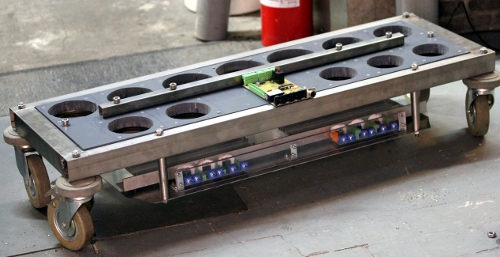 There will be enough space underneath to place the tone generator boards as
well. Thus only the midi-hub board ought to be placed on the upperside. Suffering
a lot from my backbone hernia, as much of the work is so low to the ground and
the construction is getting too heavy now to lift it up easily...
There will be enough space underneath to place the tone generator boards as
well. Thus only the midi-hub board ought to be placed on the upperside. Suffering
a lot from my backbone hernia, as much of the work is so low to the ground and
the construction is getting too heavy now to lift it up easily...
05.09.2016: Start mounting of the tone generator boards on the bottom plate.
Assembly of the power amp power supply. Mains entry with IEC sockets mounted
on the back side. First wiring up....  As
it comes out, we brought ourselves into trouble with the central mounting bar
for the windchest. With the wiring, it would be very tricky to remove it. We
might have to mount connectors for the speakers and the power supply such that
it can be taken apart without unsoldering.
As
it comes out, we brought ourselves into trouble with the central mounting bar
for the windchest. With the wiring, it would be very tricky to remove it. We
might have to mount connectors for the speakers and the power supply such that
it can be taken apart without unsoldering.
06.09.2016: First tests: The power supply is working as it should. Open voltage
without load is -18V +18V. The speakers will be wired with individual connectors for each loudspeaker pair:
4-pole IMO or Weidmueller. Color coding will be applied to the wiring.
The speakers will be wired with individual connectors for each loudspeaker pair:
4-pole IMO or Weidmueller. Color coding will be applied to the wiring.
| 22 | black |
| 23 | brown |
| 24 | red |
| 25 | orange |
| 26 | yellow |
| 27 | green |
| 28 | blue |
| 29 | purple |
| 30 | grey |
| 31 | white |
| 32 | yellow/black |
| 33 | pink |
Waiting for the M3 shock absorbers to come from Farnell. (Ettinger, Farnell
order code 1466989)
06.09.2016: Start wiring of the loudspeakers. Finishing the board assembly of
the underplate as the shock absorbers came in today. Missing PVC pipes and pieces
ordered from Audenaert.
07.09.2016: Construction of the holding chassis for the midi-hub and parser
board. This board will get a protective polycarbonate cover plate as the board
carries mains voltage. A bug found and killed in the synth board firmware: the
mute logic was inverted! Half of the wiring of the board holding chassis finished.
We forgot to mount connectors for the mute logic...
10.09.2016: Continuing wiring on <HybrLo>. As we forgot to provide connectors
for the mute inputs on the amplifier PCB's we have to use wires leaving the
boards directly...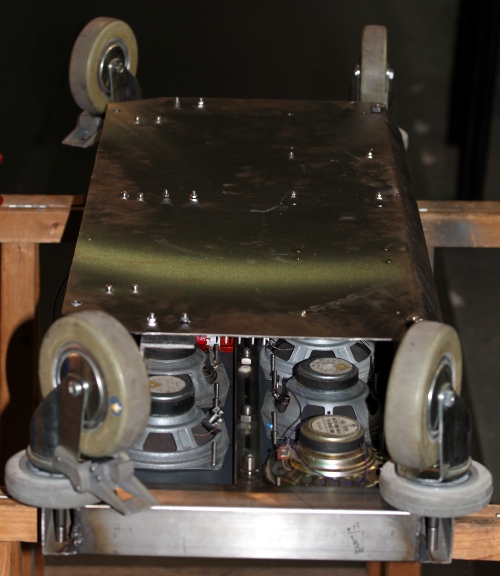 Holes
drilled for the wires going to the midi hub board.
Holes
drilled for the wires going to the midi hub board.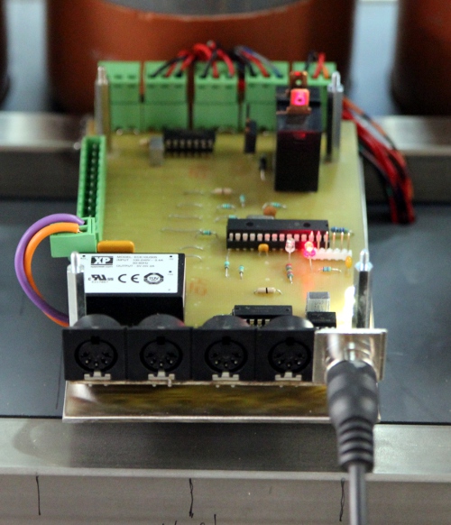 There would still be some space left for a small 12V SMPS to power some lights...
The mosfets for these are as yet not mounted on the hub board.
There would still be some space left for a small 12V SMPS to power some lights...
The mosfets for these are as yet not mounted on the hub board.
11.09.2016: Wiring in principle finished. First tests become possible... A smoke
stack appeared on power up. Amplifier power supply appears shorted, fuse melt
down. The third TDA7264 exploded... Carefull examination of the soldering of
the third amplifier (notes 26-27) revealed a short between an input pin and
the +15V power line. We replaced the TDA7264. The board now draws (unmuted)
240 mA running off a +/-15 V bench power supply. This means 80 mA per amplifier
which seems normal. The data sheet gives no data with regard to this parameter.
All amps appear working now. Making a setup for the tests with MIDI control...
The mute polarity needs an inversion. Furthermore there must be some wiring
errors as note 22 does not come from the speaker we wanted... work to clear
out. However, the first notes did sound already!
12.09.2016: Continued debug work. PicKit3 installed in the workshop for ease
of programming.  Wiring
of the connectors was all wrong but we got it all corrected now. All PIC microcontrollers
reprogrammed. First sounds demonstrated for Moniek Darge and Kristof Lauwers.
Wave shape control seems not to be working for some reason. The six highest
pipes are fully tuned and working now. Waiting for 110 mm and 125 mm diameter
PVC pipe to flow in...
Wiring
of the connectors was all wrong but we got it all corrected now. All PIC microcontrollers
reprogrammed. First sounds demonstrated for Moniek Darge and Kristof Lauwers.
Wave shape control seems not to be working for some reason. The six highest
pipes are fully tuned and working now. Waiting for 110 mm and 125 mm diameter
PVC pipe to flow in...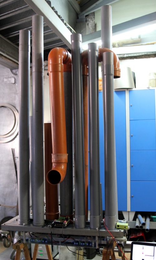 The pipes in the picture are made from recycled material. The grey ones (90
mm and 100 mm diameter) are definitive already. Fortunately our workshop has
quite high ceilings... The volume controllers for the inidividual notes are
absolutely not ment to be operated by users. They are trimmers and changing
their settings will endanger the instrument as well as bringing it completely
out of balance. Hub board PIC reprogrammed: now key pressure is working fine.
The pipes in the picture are made from recycled material. The grey ones (90
mm and 100 mm diameter) are definitive already. Fortunately our workshop has
quite high ceilings... The volume controllers for the inidividual notes are
absolutely not ment to be operated by users. They are trimmers and changing
their settings will endanger the instrument as well as bringing it completely
out of balance. Hub board PIC reprogrammed: now key pressure is working fine.
13.09.2016: Hybrlo implemented in the GMT coding for the robot orchestra. Controller
#15 added for global waveshape control, overriding individual settings with
the key pressure command. Test code for scales added in the GMT test application
for <Hybr>.
14.09.2016: Sawing of 10 mm thick standoff rings for the loudspeakers, as the
cones tend to make contact with the windchest plate. First coding experiments
using Namuda technology.
15.09.2016: Preliminary presentation of <HybrLo> to the audience in our
'Cold Boot' concert. Performance by Emilie De Vlam.
16.09.2016: Robot disassembled again, to mount the 10 mm loudspeaker stand-off's.
A hole day of work... 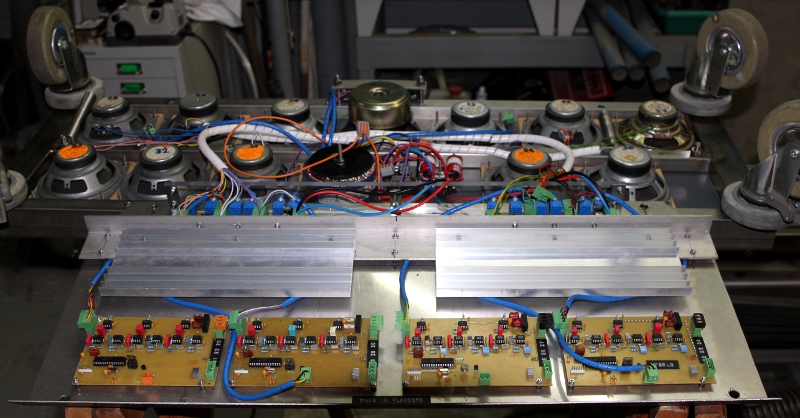 The
ordered PVC pipes still did not come in.
The
ordered PVC pipes still did not come in.
17.09.2016: White LED strip mounted on the underside of the chassis. This appeared
to be a big mistake, as the strips we used are not insulated on their underside...
Thus we had to stick them to the edge of the polycarbonate plate protecting
the potentiometer axes. 12 V Vicor SMPS (0.83A) glued to the underside (PVC
glue). LED 12V spotlites mounted on de upperside, pointing upwards. All lites
decided to be white, mapping on notes 0,1 and 2. Noticed a strange behaviour
on startup: all speakers give an uggly signal for about 2 seconds on cold boot.
We will have to find a remedy in the PIC24 firmware. Two speakers got a small
bump on the inner dome of the cone. We repaired them with a needle and than
closed the punched hole with some red Loctite silicon compound:  This
slightly lowers the resonant frequency of the speaker.
This
slightly lowers the resonant frequency of the speaker.
18.09.2016: Finalisation of the soldering of the midi-hub board: placement of
the power Mosfet's. Bright yellow power LED added on the board. The lights should
be working now. Firmware for the hub board adapted. Milling the polycarbonate
protective plate over the hub board. Test code added in GMT. It all works fine now.
19.09.2016: An easy way to stabilize the pipes could be something like this:
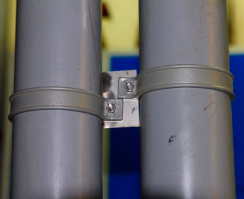 Five frontal pipe
feet glued for good using PVC glue.
Five frontal pipe
feet glued for good using PVC glue.
20.09.2016: Searching for possible replacement parts for the speakers. Four
Dayton DS115-8 4" speakers ordered from Parts Express. Visaton SC13-8 (Reichelt)
could also be a candidate. We will add a table with possible alternative speakers
in the maintenance section at the bottom of this webpage. Further work on the
firmware for the note generator boards. Release-not-working bug found and killed.
Board for notes 22-24 reprogrammed. Code modified such that waveform modulation
during a note is now possible using the key pressure command.
21.09.2016: All synth boards reprogrammed. Start implementation of the MIDI
program change command, to simplify presets for the users: we could have a Pizz
bass, a string bass, an organ bass, a sfz bass etc... preset. Still waiting
for PVC to flow in... Stuck on deliveries.
25.09.2016: Missing 100 mm PVC pipe fitting found on the flea market. Base for
pipe 28 finished. Pipes 22 to 27 remain to be done...
05.10.2016: Users manual for the robot lights
updated with instructions for HybrLo. Still stuck on deliveries to continue
work.
07.10.2016: All pipe holders glued to the windchest plate. Tubes diameter 110
mm sawn to size. Still no supply of grey 125 mm diameter PVC pipe and MF-elbows.
These are required for notes 22, 23, and 24. Trying to find someone with a car
to get more tubes at Deschacht, Antwerpse Steenweg... Start making of the U-bends
in the pipes. Only the seven lowest pipes will get a U-bend. Inventory of missing
parts: 5 elbows diameter 125 PVC or 6 MF elbows, glue mount. 3 meters of diameter
125 grey PVC pipe. All pipes finished so far, labeled with Dymo labels for ease
of mounting.
08.10.2016: Up to Deschacht to get the missing PVC pipes and elbows, with Peter
Van Lancker. Pipe work in principle finished now, apart from some minor esthetic
issues. First tests with all pipes cut to size and tuned. Some U-turns may need
a bracket to keep them perpendicular. Oddly enough, standard PVC elbows do not
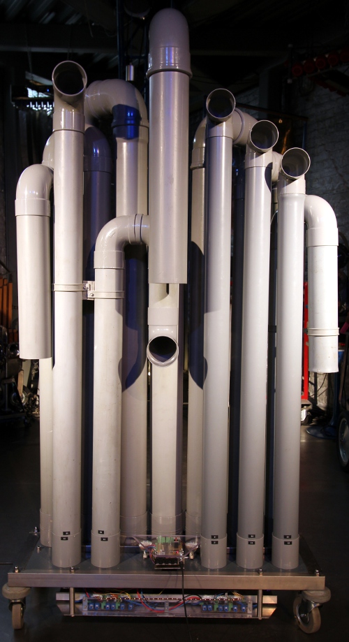
make right angle degrees but rather 87 degrees angles. The picture was taken in our workshop during construction.
09.10.2016: Fine tuning and minor corrections on pipes 29 and 30. Pipe 29 lenghtened
a bit and pipe 30 given a single elbow on its end. Firmware for all 24F PIC's
upgraded: now pwm changes are no longer immediate but performed after each PWM
cycle. Program changes implemented in this firmware as well.
10.10.2016: Firmware greatly improved. Now modulation of volume during a sounding
note is made possible. All levels now make use of a 40dB log scale. Pipes for
notes 31, 32, 33 given an elbow on the top. It just looks better...
11.10.2016: Considering to extend the note range with 3fo and 4fo pitches...
Tried out. We implemented every note now in 4 octaves, thus the range of the
instrument becomes 22 to 69. However, keep in mind the instrument remains limited
to 12 note polyphony and octaves are mutually exclusive. With this range <HybrLo>
can be used as a full and extended replacement for <Bourdonola>. Controller
#90 implemented on the hub board, to allow easy limiting the ambitus. <HybrLo>
placed in the robot orchestra for first evaluations and tests: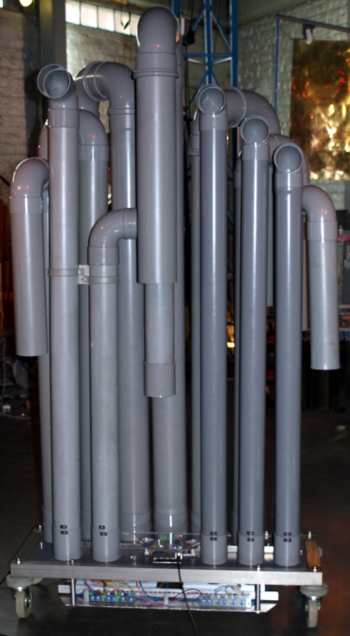 Awaiting feedback...
12.10.2016: All levels and volumes now have a 40dB range and full log scaling.
Elbow added on pipe 29. The 40dB scale after all does not fullfill our expectations.
So we changed it back to 60dB. All level related parameters now make use of
this logarithmic scaling.
13.10.2016: Frequency uncertainly introduced in the firmware and implemented
for controller #1. This models acoustical sounds much better than pure periodicity.
In fact we modulate the duration of the off phase in the oscillators. Thus the
on-pulses are kept constant for any given frequency. As a consequence the spectrum
stays more stable than in the case we would have randomized the entire period
as such. Scaling for attack and decay reduced to 206ms. Release time kept with
a range of 0-512ms on request of Kristof Lauwers. Pleased with the result now...
14.10.2016: Finalising the five presets in the firmware after extensive testing
of the parameters by Kristof Lauwers. Firmware upgraded again.
26.10.2016: Photosession with HybrLo...
16.09.2018: HybrLo is replacing Bourdonola in all robot orchestra concerts up
to the end of october, as Bourdonola is off to Manchester. Midi files adapted
accordingly.
07.12.2020: a bug discovered in the PIC 24EP code: reading 32-timers with TMR2
and TMR3 must use TMR3HLD to read the msb, not TMR3 directly. This bug was found
in all projects using this chip since 2016: <So>, <Autosax>, <Flut>,
<Hunt>, <Bug> , <Pi> and <2Pi>. Fortunately we can reprogram
the PIC's without disassembling the instrument!
14.12.2020: Revision of the IC 24EP firmware. Controller 100 added to change
the dynamic lookup tables.
15.12.2020: We see further improvements possible...however, if we implement
these fully, <HybrLo> becomes a version 2 robot as we will loose full
compatibility with existing midi-files and applications.
16.12.2020: A new version of the fimware ready now to be tested on the hardware...
TO DO:
Maintenance information:
Circuit diagrams:
General overview:
Power supply:
Transformer:
MCTA225/12, Farnell order nr.9532790.
Note generator and filter boards:
Amplifier boards:

Midihub and parser board:
PCB's:
Note generator boards with active filters and multipliers (Eurocard size: 100 mm x 160 mm, single sided PCB):
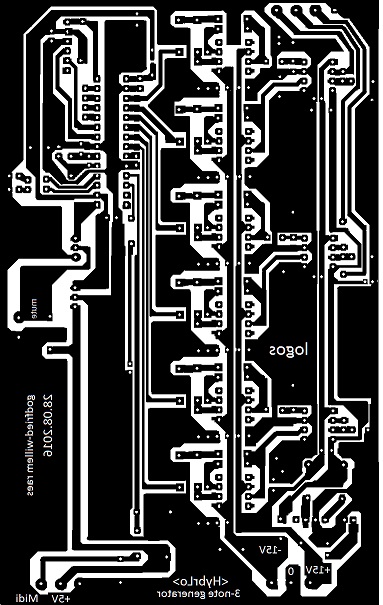 These boards
are mounted op the bottom plate with M3 male-male shock absorbers as stand off's.(Ettinger,
Male-Male, Farnell order code 1466989).
These boards
are mounted op the bottom plate with M3 male-male shock absorbers as stand off's.(Ettinger,
Male-Male, Farnell order code 1466989).
Amplifiers PCB's: (at 200%)
Loudspeaker sizing:
Critical evaluation:
by Godfried-Willem Raes
Further reading on this topic (some in Dutch):
Audsley, George Ashdown 'The Art of Organ-Building', ed. Dover Inc, NY,1965,
(first edition: 1905) ISBN 0-486-21314-5
D'Appolito, J. 'Luidspreker-meettechniek', ed. Segment BV, Beek , Nederland,
2000, ISBN: 90 5381 116 8
Raes, Godfried-Willem , Expression
control in musical automates
Raes, Godfried-Willem, <Hybr>
Raes, Godfried-Willem, <HybrHi>
Maintenance and disassembly instructions:
Before undertaking any repair on this robot we strongly advise to first read
through our construction diary, as this will clarify fully how the machine was
originally designed and assembled.
If the machine has to be taken apart, perform following steps:
1.- remove all the pipes. On replacing them, apply a thin layer of vaseline
to the bases.
2.- Place the machine upside down on two stands. Make sure it doesn't rest on
the midi-hub board.
3.- Loosen the four long M10 bolts that hold the bottom plate together with
the windchest.
4.- Loosen all four 3-pole Weidmueller connectors carrying the 5 V and MIDI
lines.
5.- Loosen all six 4-pole Weidmueller connectors that connect the speakers to
the amplifier board. Note the order! The wires are color coded.
6.- Loosen the wires that feed the mains voltage to the MIDI hub board.
7.- Now the underplate can be fully removed and serviced. The processor boards
and amplifier boards can now be taken apart.
Loudspeaker replacement possibilities:
| brand / type nr | P | fres | dB | range | impedance | price | source |
| Visaton VIS SC13-8 | 40W | 78Hz | 90dB | 8 Ohm | 21.7 Euro | Reichelt | |
| Dayton DS115-8 | 35W | 55Hz | 60-8000 | 8 Ohm | 14$ | Parts Express | |
| Visaton VIS FR13-4 | 30W | 100Hz | 65-20000 | 4 Ohm | 11.45 Euro | Reichelt | |
| Axton ATF130 | 90W | 70-25000 | 4 Ohm | 49 Euro |
Lights:
Robody picture with <HybrLo>:
Candidates? Welcome!
[EOF]