Piezo disk contact microphones: problems and solutions
Piezo disks are used almost universally by experimenting musicians all over the world, not in the last place because they are cheap. They have been around since the mid seventies of last century. (1). Generally people connect them to unbalanced microphone inputs of power amplifiers. The resulting sound is more often than not, harsh and metallic. Here we propose a much better solution, based on a good understanding of the nature of piezoelectric transducers. A piezo disk basically is and behaves as a capacitor, generating a voltage when exposed to vibration. As a consequence, the impedance is a function of excitation frequency and can be considered infinite when no signal is generated. Such a generator makes a very bad source for a regular microphone input with constant input impedance.
Here is a much better solution:
The opamp in this circuit is configured as a current amplifier. Basically the piezo disk connects to the inverting input and thus sees a zero impedance. It is virtually shorted. The current produced by the disk is amplified by a factor Av = Xf / Xi, wherein Xf = 1 / (2.Pi,f.Cf) and Xi = 1 / (2.Pi.f. Ci). Substitution then leads to the conclusion Av = Cp /Cf , where Cp corresponds to the capacitance of the disk, generally in the order of 10 nF to 24 nF. (see table below). Note that Av is inherently independent of frequency here, thus we avoid the sharp and metallic sound obtained when using a non-inverting opamp configuration. The 22 MOhm resistor limits DC gain and prevents oscillation. It determines the low frequency roll-off. The higher this resistor, the lower the cutoff frequency. Resistors with such high values - values up to 100 MOhm can be used- are not common. (2) It you are in trouble tracing them, you can also use common 10 MOhm resistors. Note that when using very high resistor values here, the opamp used must be a type with very low drift. The 1N4002 diode (about any type will do) serves as polarity reversal protection, no luxury as we noticed many users try connecting a battery in its holder until it fits... The TLO71 opamp specified here, operates at 1V below its minimum Vcc-Vss range, yet it works. It can be exchanged for any low noise low voltage type. We designed this circuit some 35 years ago, at a time low voltage op amps were not readily available, the standard being -15V and +15V. Here is a simple single sided PCB for the circuit (here at 200%, so for etching you need to reduce to 50%). The PCB has the size of a 9V battery and thus can be mounted on a battery holder.
A typical application of this circuit was for an amplifier for a contact microphone picking up the vibrations of a cello bow. For this project, a small piezo disk was clamped via a small wooden bridge between the bow hair and the wood of the bow. Here is a picture:
A shielded highly flexible silicon wire should be used, as stiff wires will cause unwanted noises.
A variation of this circuit was worked out to facilitate connection to standard mixing boards with provisions for phantom powered microphones. The phantom voltage is 48V but only a few mA can be drawn, so we must take care to select a low power opamp in the circuit:
. This is a transformerless design, but audio transformer designs are possible as well. Here is a circuit for a PCB accommodating 4 separate piezo disk inputs and four phantom powered transformer balanced outputs:
. The PCB for a single channel looks like this:
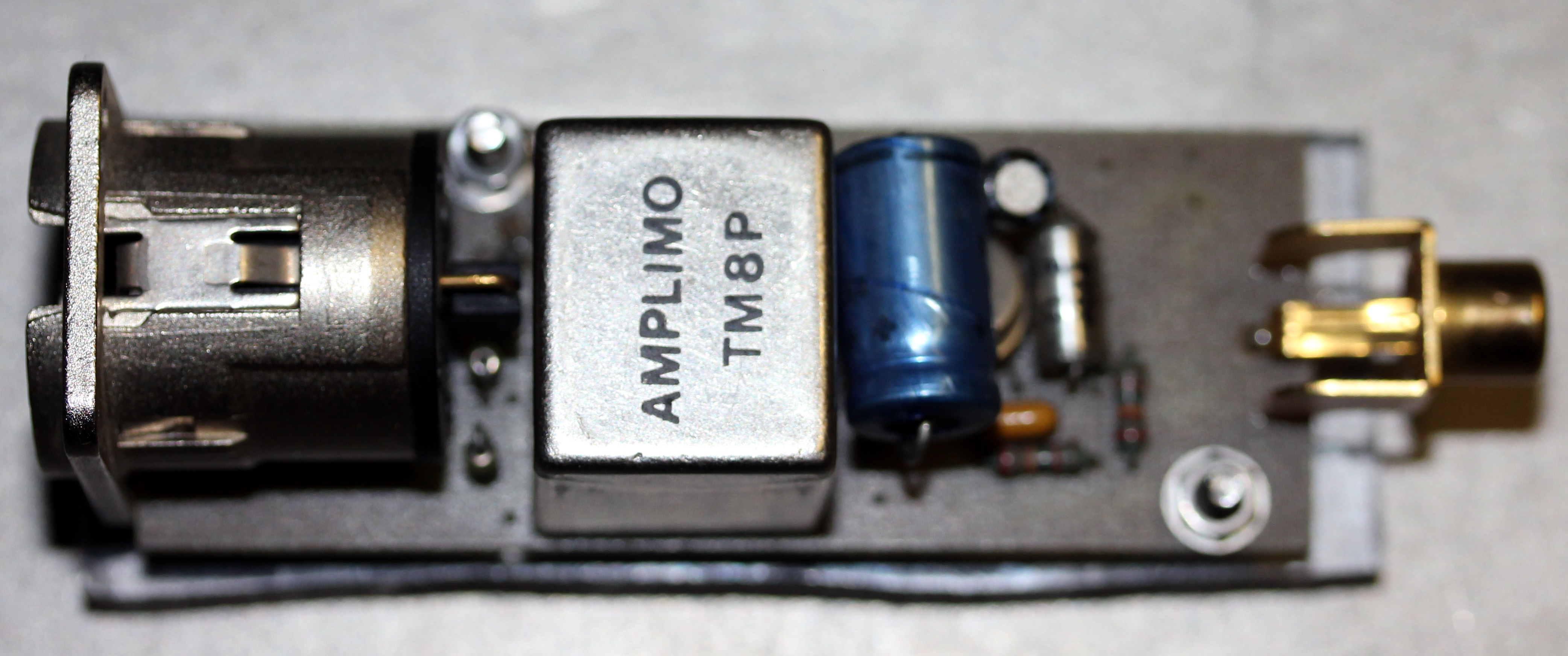
This PCB was designed to use Amplimo audio transformers. If other transformers are used, the foot print may need to be changed accordingly. Here is a picture:
One serious problem often met when using piezo disks as pickups in live electronic projects is that very high voltages spikes can be produced on strong excitation of the disks. This can eventually lead to destruction of either the power amplifier or the speaker system driven by it. Also, it's not too healthy to the ears of the audience... Hence the need for some kind of limiting or even compression of the signals.
Here is a battery operated solution for a limited preamplifier for piezo disks:
The diode circuit following the first amplifier stage, makes a limiter. If the signal on the input exceeds the diode forward voltage drop (ca. 250 mV for germanium diodes, 600 mV for silicon types), the excess signal flows through the capacitor and high frequencies get attenuated more than low frequencies. With the 1k series resistor and the 47nF capacitor as drawn, the -6 dB point is at 3.4 kHz. Thus it makes a simple soft clipper/compressor. The response time is determined by the RC time for the 47 nF and 2.2 M Ohm combination, so in this case 100 ms. It is the kind of circuit that once was very popular amongst short-wave radio amateurs for listening to Morse code broadcasts. The germanium diodes (AA119, OA91 etc.) nowadays may be hard to find. (3) They can be replaced with BAT86 Shottky diodes (Vf = 260mV). Do not use regular silicon diodes, as at clipping, they will cause the second op amp to saturate. This is because the peak voltage of the signal with regular silicon diodes equals 1.2 Vpp. As the second op amp has a gain of 10, the output should become 12 Vpp, a value that could only be reached when the power supply is higher than 12 V. If you find the operation of the soft limiter still sounding too harsh for your application, increase the value of the 47nF capacitors. If you want to increase the attenuation, increase the value of the 1k resistor connected to the output pin 6 of the first op-amp.
The final opamp, just mixes and amplifies the signal further to a strong and hefty line level. If long cables are to be used, select an AD820 opamp rather than a TLO71.
A typical application for such a circuit was in the construction of a pick up to be used to amplify human heart beats. For this project a quite large piezo disk should be used (30 mm diameter or so) and a weight should be glued with silicon compound to the upperside of the disk. This kills unwanted higher frequency signals right at the source. Of course, components have to be selected for optimum very low frequency performance. The limiter circuit adequately protects against spikes here. Similar applications are: larynx microphones and monitoring devices for all sorts of body sounds. For my own 'Woman's Quartet', I even made a set of four vagina microphones...
As in some applications such as sound sculptures and audio art, often the signals of more than a single piezodisk are to be combined, a mixer circuit comes in handy. Here is a small PCB for a simple but effective 6-channel mixer: (reduce to 50% for printing the film).Here is the corresponding circuit:
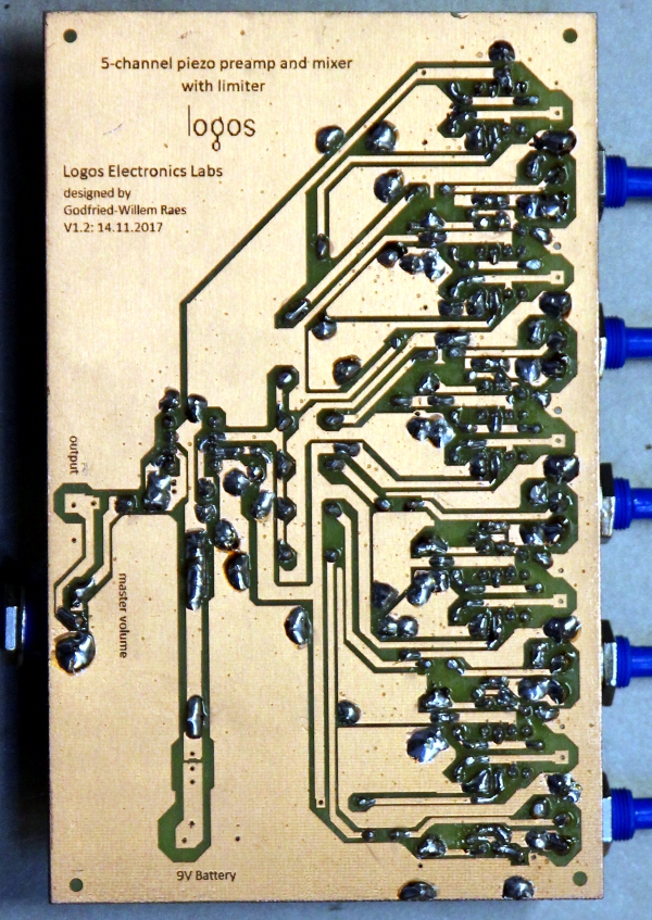
In the following and more elaborate project design, we combined these ideas to realize a 5 channel piezo disk mixer, with individual channel volume controls as well as a master volume control. Here is the circuit:

Note that metal film resistors should be used throughout for lowest possible noise. The mixer stage can make use of an TLO71. AD820 (datasheet) or TLC071 (datasheet) opamp, but if the circuit is to drive long cables, the AD820 makes a better choice, as it can drive quite large capacitive loads without stability problems. The headroom and maximum output voltage swing of this circuit can be improved by raising the power supply voltage. Make sure not to exceed the absolute maximum ratings for the opamps used. If different types of opamps are used in this circuit it is mandatory to go for JFET input low noise types, preferably with output swings up to the supply voltage. Also, make sure to check the minimum Vcc voltage for the part. If specified at higher than 9V, consider using a 12V or higher voltage battery pack. Our favorite long line driver op amp, the rock stable LF356, unfortunately requires a 30V power supply and cannot be used, unless we redesign the circuit with a proper -15V - 0 - +15V power supply. The AD820 performs very well here, but it's a rather expensive component.
If you want to check it out and build it yourself, here is a single sided PCB design (at 200%):
In quite many experimental instrument building and soundsculpture applications, it is not required to build the circuit with input volume control potentiometers. If the circuit is to be build into such a project, the potmeters can be replaced by fixed resistors. Determine their value by making a good sounding balance, measure the resistance value of the potmeters at that setting and replace them with fixed values. Not only this improves lifetime of the circuit, but also it entails quite a saving on building costs. Renounce the tempting idea to replace the potmeters with trimpots, as these components are amongst the least reliable of all. Of course this also applies to the output volume control. Generally the only thing you have to make sure, is that the output is a nominal 0dB level, or whatever level you decide to stick to. Remind you: 0dB means 0.775 Vrms, or 2.2 Vpp.
If you want to etch the PCB, save the gif image on your computer and laser-print it on transparent foil reduced to 50% in size. The circuit fits a standard Eurocard PCB (100 mm x 160 mm). Assembled and tested circuits can also be bought from the Logos Foundation for approximately 250 Euro's. Inquire by e-mail to mattias@logosfoundation.org. Silicon mount piezodisks can be obtained as well.
As the value of the feedback capacitor in the preamp circuit depends on the capacity of the piezo disks connected, we measured some different types. This may be useful for users not equipped with a capacitance meter or a detailed data sheet for the product. As you will notice, the capacity is not always a function of size, as it also depends on the thickness of the piezo ceramic layer. Here are the results of our measurements:
disk diameter / thickness measured capacity practical value for Cf source remarks 12 mm 0.22 mm 7.8 nF 820 pF Farnell nr.2433032 fres= 9.5kHz 15 mm 0.22 mm 9.35 nF 1000 pF Murata
Farnell nr.2443195
fres = 6 kHz 15 mm 14.6 nF 1500 pF 15 mm 0.13 mm 34 nF 3300 pF Multicomp
Farnell nr. 2667639
fres = 4 kHz 20 mm 0.2 mm 10 nF 1000 pF Murata
Farnell nr. 1192520
fres=6.3 kHz
wired
20 mm 0.22 mm 20 nF 2200 pF Murata
Farnell nr. 2443197
20 mm 0.4 mm 6 nF 680 pF Multicomp
Farnell nr. 2433033
fres = 6.4 kHz 27 mm 0.52 20 nF 2200 pF Multicomp
Farnell nr. 1675548 (wired)
Farnell nr. 2443198 (unwired)
fres = 4.2 kHz 28 mm 23.8 nF 2200 pF Hungary 30 mm 26.1 nF 2700 pF Hungary 35 mm 0.3 mm 30 nF 3300 pF Murata
Farnell nr. 1192552
fres = 2.8 kHz 35 mm 0.53 mm 22.9 nF 2200 pF Murata
Farnell nr.2443199
fres = 2.8 kHz 35 mm 0.51 mm 37 nF 3300 pF Multicomp
Farnell nr.2433034 (unwired)
Farnell nr.2433035 (wired)
fres = 2.8kHz 50 mm 24.8 nF 2700 pF Conrad
order nr. 541-022-08
type FT-50T 6 mm x 14 mm square 4.7 nF 470 pF Hungary If you have no idea what kind of piezo will be connected to the circuit, it is a good compromise to go for a 1.5 nF value.
Here is a picture of the first prototype of the complete circuit:
It may help potential builders to figure out correct component placement on the board. The battery holder and the piezo disks are not yet connected on the picture. Here is a view on the copper- and solder side:
For people preferring a version using a dual bipolar power supply (or two 9V batteries), we worked out a circuit as well. Note that this version shows a clear saving on relatively expensive capacitors. Another advantage of this version is that the inputs for the piezo disk are at ground level.
Current consumption of the circuit is ca. 10 mA, using six AD820 opamps, so a regular 9 V alkaline battery (the capacity is ca. 550 mAh) can be used with an expected lifetime of ca. 40 hours. For the dual supply version, this becomes 80 hours. Note that TLO71 opamps draw about twice as much current as their AD820 counterparts.
In the early days of live electronics, between 1965 and 1973, one of the devices seen all over setups was the infamous Eagle mixer, a very small 4 input line level mono mixer. The internal circuitry was of an utmost simplicity: a passive mixer followed by a 1 transistor (a Japanese PNP germanium type...) emitter follower. This mixer was very cheap and its performance pretty poor as well. It produced a lot of noise. However it was in use amongst hundredths of musicians and has populated just as many stages. With some nostalgia, we remade such a four-input mixer, here in a version for four piezo disks, in the same form factor. The PCB would even fit in the old housing, but if anyone considers reusing an old cabinet, please replace all potentiometers as the original types are of an extremely lousy quality.
To facilitate component placement on this PCB , here is a sketch:
A single Eurocard (100 x 160) PCB will accommodate two of these circuits. Here is the picture of the housing, internally completely rebuild:
All of the circuits above have been copied and used by quite many musicians and quite a few of them we did build on demand. A request that regularly came back, was for a design using 1/4" jack input and output plugs, battery operated. In 2019 we came up with a special design, using a dual opamp. This is the circuit:
As to the opamp used here, a low voltage type such as the TLC277, is even a better choice (although a lot more expensive) than the TLO72 specified in the circuit drawing. Here is is picture of two buildup PCB's:
If the vibrations on the piezo disc are too strong, the amplifier may go into lockup. In such cases, we advise users to rather use damping material on the piezo rather then changing the circuit component values. The more you mechanically damp the piezo disk, the more you damp its resonance peak. If the saturation persists, change Ri to 100k or so. A Eurocard PCB design, accommodating six preamps is available.
Godfried-Willem Raes
Ghent, November 2017
rev.May,2019
Notes:
(1) A historical source on piezo-electrics is: Ed. Palmans, 'Piezo-electriciteit'. ed. P.H.Brans, Antwerpen,1942. A bit more recent: J.W.Waanders 'Piezoelectric Ceramics', ed. Philips Components, Eindhoven 1991. Early adopters of piezo disks in experimental musics were Richard Lerman, Alvin Lucier, Takehisa Kosugi, David Behrman, Hugh Davies, Hans Karsten Raecke, John Hudak, Maurizio Kagel, Karlheinz Stockhausen, Daniel Senn, Michel Waisvisz, Paul Panhuysen, Dick Raaijmakers, Wolf Dieter Truestedt and many others.
(2) 100 MOhm resistors are a/o. made by Ohmite and can be ordered from Farnell (ord. nr.2664957). They are a lot more expensive than regular types.
(3) Not a single germanium diode can be found in Farnell's otherwise extensive catalogue. AA119 diodes are popular in music circles and go for prices in the order of 4 Euro's a piece on Ebay. Matched pairs go even higher prices. The reason why these diodes are so much looked after is that their forward voltage drop is very dependent on the current flowing through the diode. (cfr. data sheet). Hence its application in quite many simple audio compressor circuits. This particular circuit has been around at least since the early seventies:
We have no clue as to the original author. The trim potentiometer is used to adjust the decay time of the limiter-compressor. Note that the input impedance is very low and thus the circuit must be driven by an amplifier output. The output also requires buffering, as it has a high impedance. Worked out with this in mind, the practical circuit becomes:
At Logos Foundation we still have quite some new AA119 matched paired diodes in stock. If you want to buy some, we charge 3 euro's a piece. They must be bought in multiples of two. Order by e-mail.
We also designed a PCB for a single supply version, operated with a 9V battery and an input for a piezo disk. Here is the circuit drawing:
:, and here is a PCB to go with it:
This version can easily be built into a regular audio control pedal. With some slight modifications in component values, at can also be used for electric guitars and similar sound sources:
Stichting Logos
Kongostraat 35
9000 GENT, (Belgium)
Bank account: BE98 0000 4890 7093
to index-page Godfried-Willem Raes
Research into legacy electronics funded in part by the Orpheus Institute. This article is a part of a research project on historical performance practice involving live electronics we are preparing for the Orpheus Institute (HIPEX project).
www.orpheusinstituut.be

last update of this page: 31.05.2021 by the author.


