The experimental legacy
dr.Godfried-Willem Raes
postdoctoral researcher
Orpheus Institute & Logos Foundation
2022-2023
Electromagnetic pickups and transducers
Magnets and electromagnets are at the core of an awful lot of devices we encounter daily around us. Obviously they are essential in the construction of almost all kinds of motors, but also in audio devices they are indispensable. Loudspeakers and microphones are likely the first devices that will come up in our mind. But, also they are an essential part in musical instruments: the pickups in electric guitars for instance, but also instruments such as the Fender-Rhodes piano, the Hohner pianet, the e-bow, the mellotron, pipe organs, the neo-Bechstein piano as well as nearly all musical automatons build after world war 2.
The invention of the horse shoe (electro)magnet is attributed to William Sturgeon (1825) . He found that the field strength of a magnet could be much improved by bringing the poles near to each other. The horse shoe magnet made telephony possible, not only for its use in the generator used to make a call, but also for the construction of the listening part of the telephone horn. In order to become an electromagnetic transducer, the only thing required was to wind a coil around the legs of the magnet. By sending a small electric current through the coil, the magnetic strength could be modulated and hence the force excerted to a ferromagnetic object such as a plate-membrane in the immediate neighbourhood. But also for the early development of radio, such transducers did prove to be indispensible. Here are legacy headphones made after this early recipe:
Disassembled they look like this:
The earpiece is made of bakelite and screws on the holder. The membrane is made of thin carbon steel and sits in front of the U-shaped coil assembly with a gasket in thin cardboard. This gasket determines the dynamic range to quite a large extend. If it is too thin, the membrane may make contact with the coil and cause terrible distortion on high input signals. If it is too thick, sensitivity and loudness will suffer.
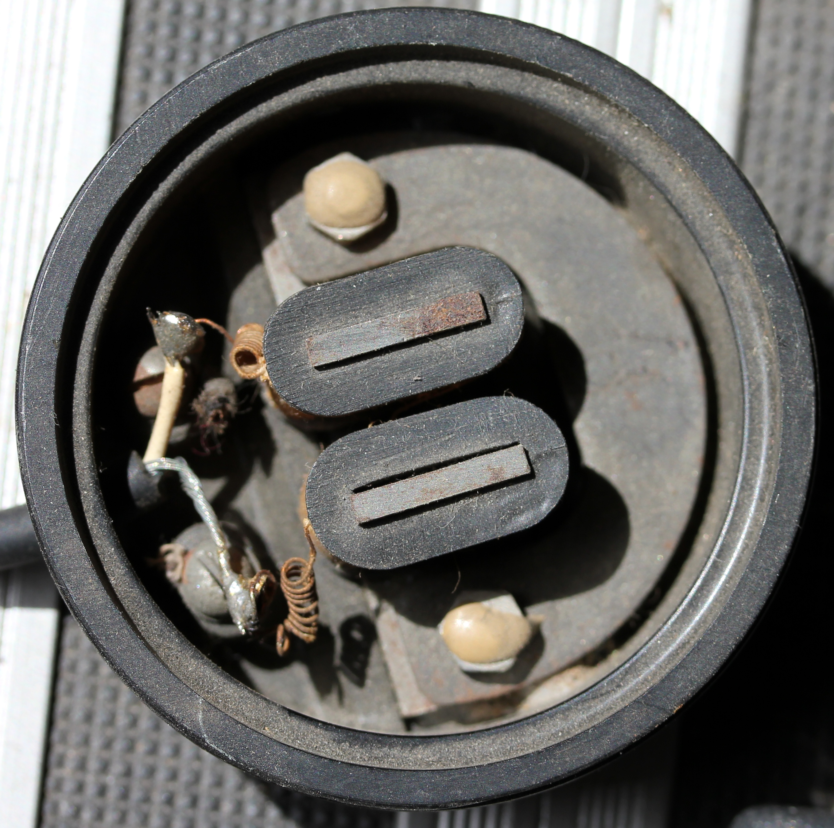
On the following pictures - three different specimens - we see the U-shaped magnet, the steel membrane that in normal operation is just in front of it, removed.
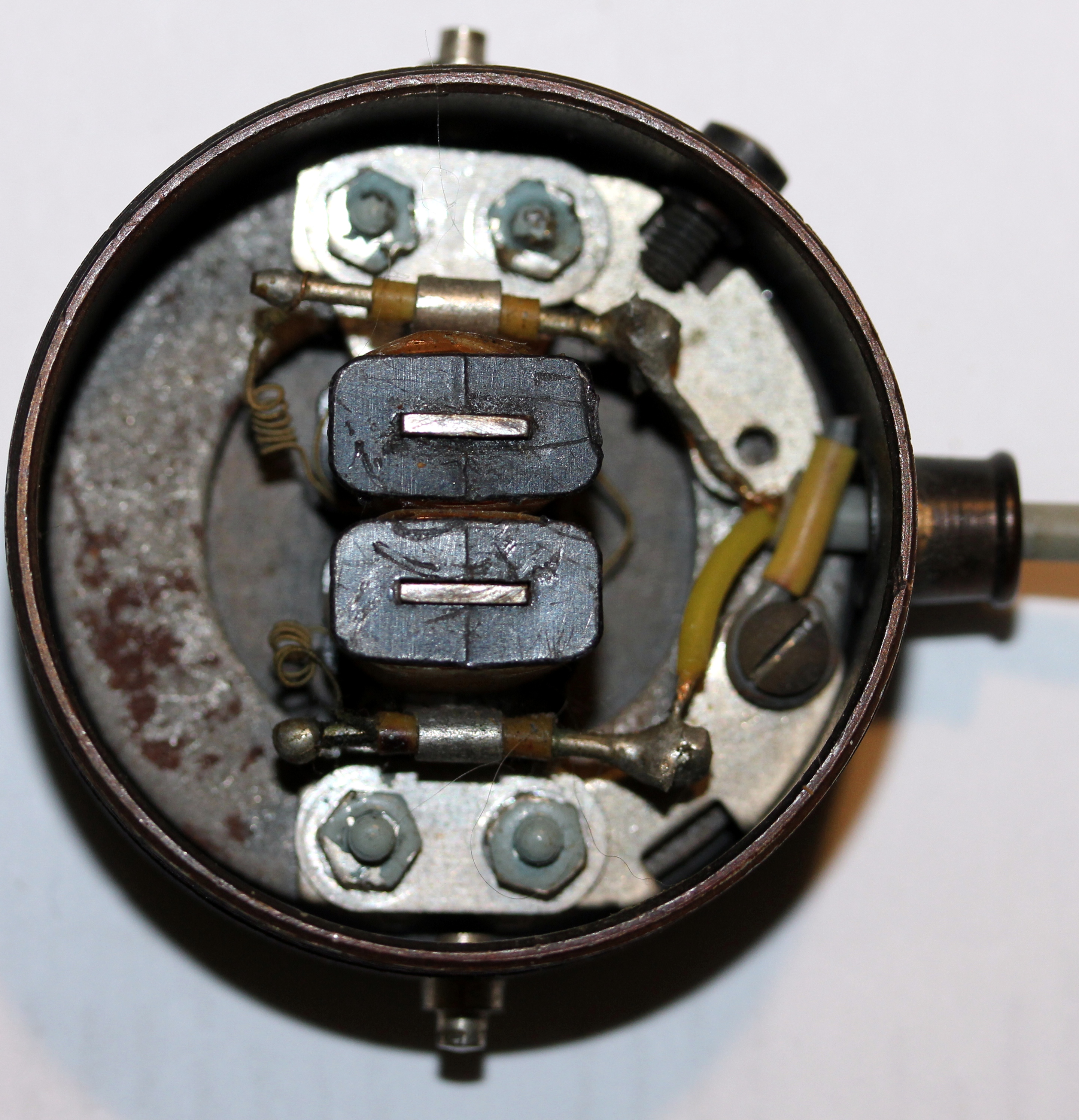
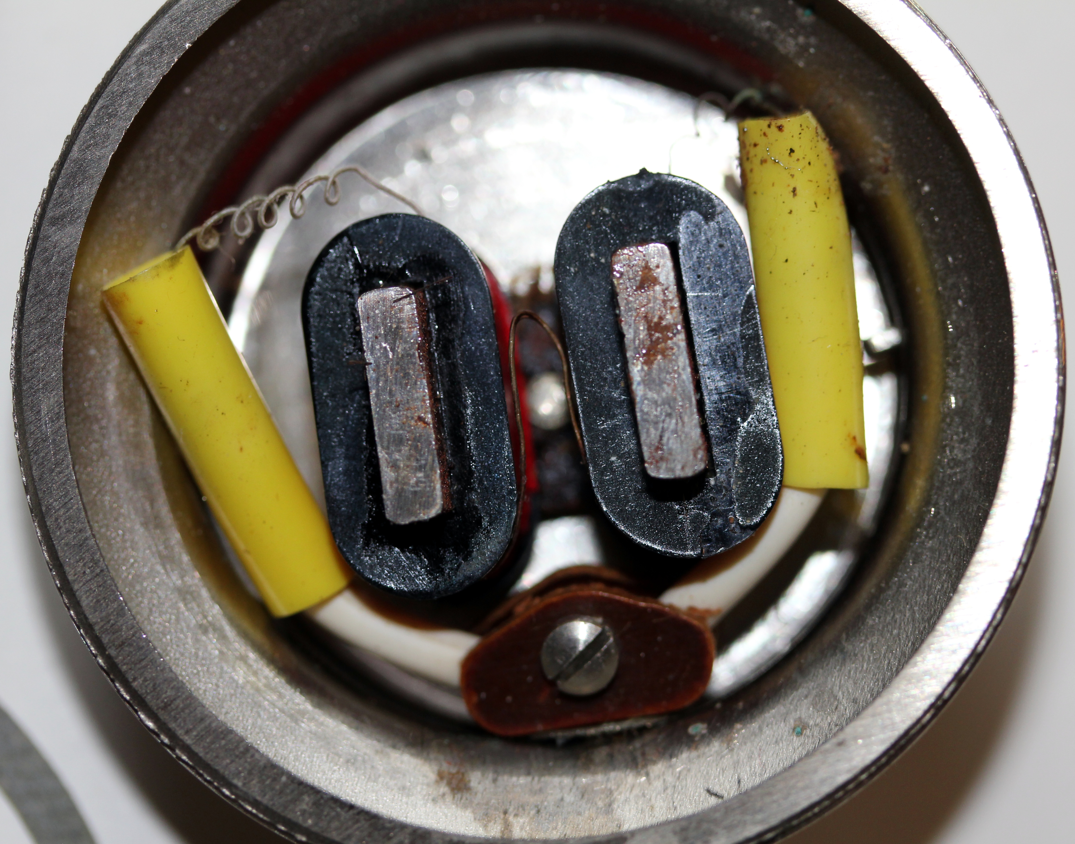
The first two types use 'external magnetisation', hereby the semicircular metal part is a permanent magnet coupled to the L-shaped iron cores holding the coils, The third type uses a permanent U-shaped magnet holding the coils directly. All types shown here have an impedance of 2000 Ohms. Nevertheless, the last shown type is a lot more sensitive than the first couple.
Although made and designed for the earpiece part, the device is perfectly reversible and thus works as well as a pickup. For such use, the membrane is usually removed and replaced with the ferromagnetic vibrating object one wants to pick up. In this shape we find them as transducers in many instruments and lots of composers and performers in the world of experimental musics, have used them. Most self-made instruments by Hugh Davies, make use of such pickups, invariably recycled from old military headsets. Also the German composer and performer Wolf Dieter Truestedt uses them for the construction of his wind harps.
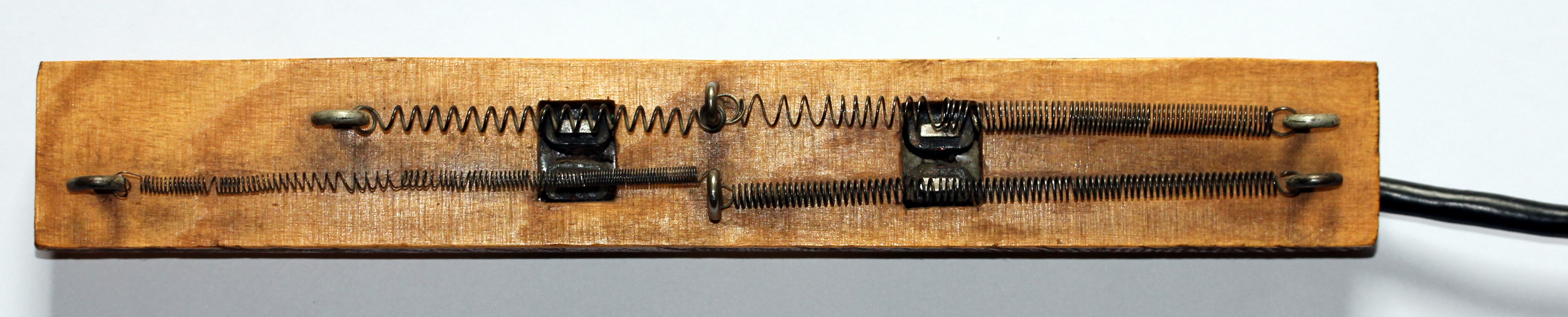
Here is a picture of one of Hugh Davies' original springboards, made in 1976:
If used as a pickup for vibrations in and of ferromagnetic materials (strings, springs, steel plates, tin cans...) it is mandatory that the U-shaped core of the pickup forms a permanent magnet. The problem that invariably shows up when using period transducers, is that their magnetic properties tend to be only a fraction in strength of what they were when new. In order to prevent demagnetization of horse shoe (and in fact this applies to all magnets) magnets, one must store them with a magnetic shunt bar between the poles. Of course none of the left over period transducers were stored that way and thus, you can be pretty certain that demagnetization has occurred. In theory it ought to be possible to repair the permanent magnet by applying a DC current of a polarity reinforcing magnetism for a substantial period of time. The problem is that often the wire gauge of the coils is too small to allow a substantial current to flow. The current to be applied ought to be such that any further increase does no longer lead to an increase in magnetic strength. This strength can easily be estimated using a magnetic compass at some distance from the pickup. If such a strategy can not be followed - generally because the coils get too hot - one can consider to apply a modern neodymium magnet to the existing core. This trick, by the way, also helps to restore old pickups that lost sensitivity on electric guitars.
Common impedance's for these transducers vary between ca. 4 kOhm and some 24 Ohms. The input impedance of the preamplifiers or mixer inputs to match these transducers must be ten to twenty times the impedance of the transducers. If the input of the preamp is too low, high frequency reproduction will suffer. This is because the transducers are inductive devices wherefore the impedance rises with frequency : Xl= 2.Pi.f.L. The exact opposite of piezoelectric devices. Hugh Davies (1943 - 2005) always used them in combination with his (battery powered) Uher mixer, having 47kOhm input impedance.
Other mixers that were very popular (and cheap...) in the early seventies were the Eagle mixing boards using slider faders instead of the rotary potentiometers in the oldest models.
The electromagnetic pick-ups used in commercial instruments such as the Fender Rhodes piano and the Hohner pianet where obviously not recycled parts, but custom made transducers. Their construction nevertheless is quite simular to the devices described above. Here is a picture of the transducers used in the Hohner pianet:
It is worth noting that all 55 transducer coils are simply connected in series. The use of the term 'connected in series' may even be an overstatement in this case, as in fact the entire transducer assembly is wound using a single uninterruipted copper wire. The mounting plate under all the coils, is a strong permanent magnet.
Moving coil transducers
The basic construction of such contactmicrophones is a fixed permanent magnet and a coil that is suspended around the magnet and free to move. Such constructions were on the market between 1975 and 1985 and advocated for use on the double bass, the cello and the piano. The moving part being light, the transducers works on the principle of inertia. They are very sensitive to the direction of the vibration and their sensitivity is at maximum for movement and vibration perpendicular to the stave magnet. Here is a popular type - we bought it in 1974 - made by FreeTone:
Opening the aluminum case reveals the utmost simple construction and the moving coil:
The screening here is very good and hence hum is reduced to a bare minimum. A particular advantage of this type of transducer is their behavior at overload: they do not clip nor saturate but rather output a compressed signal on exposure to very high excitation levels. This property makes them very suitable as pickups for heavily vibrating objects. We have used them on carillon bells, where the use of piezo disks was impossible because the vibrations were way too strong. In fact, its pretty easy to make them: one can use small (<50mm) loudspeakers with impedance's between 16 and 50 Ohms, on which the entire paper cone should be cut away such as to only leave the moving voice coil. A sharp razor blade must be used and one has to be very carefull not to cut through the tiny copper wires leading to the voice coil. The paper cone must be cut away to make the transducer insensitive to acoustic sound. They can be used just like normal dynamic low impedance microphones and connected as balanced sources to standard mixer inputs with XLR connectors. A disadvantage of this type of transducer is that their mass functions as a damper on the source of vibration. Thus their use will be limited to those cases where the proportions of the vibrating body to the mass of the transducer is large. Hence their indication for the double bass and the piano.
It is important to distinguish two distict electromagnetic transducer types: first, those using a permanent magnet whereupon a coil is wound (this is the case for all transducers described above but also for loudspeakers) and those designed to pick up changes in magnetic fields. In this category we meet the tape recorder heads as well as the telephone pickup coils that were popular with old telephone sets, to pick up or amplify telephone conversations. Remind you it used to be strictly illegal to make any galvanic connection to the public telephone network! Also the earliest telephone modems -acoustic modems they were often called- made use of such technology for the same reason.
Pick-up coils have been used by sound artists and performers to listen to the internal guts of computers and other digital equipment. There is quite an interesting sonic world to be explored in there...
note: buzzers and vibrators exist in both flavours. Comment on octave doubling!
Photocells, light sensors and optical sensors
Vacuum tube photo cells
Devices to convert light into electric signals were already discovered and available in the 19th century. In fact, the discovery of the photo-electric effect was at the base of quantum physics and Einsteins relativity theory. Photons are freeing electrons from a suitable cathode, thus causing an electric current to flow.
Here are a few historic photo cells:
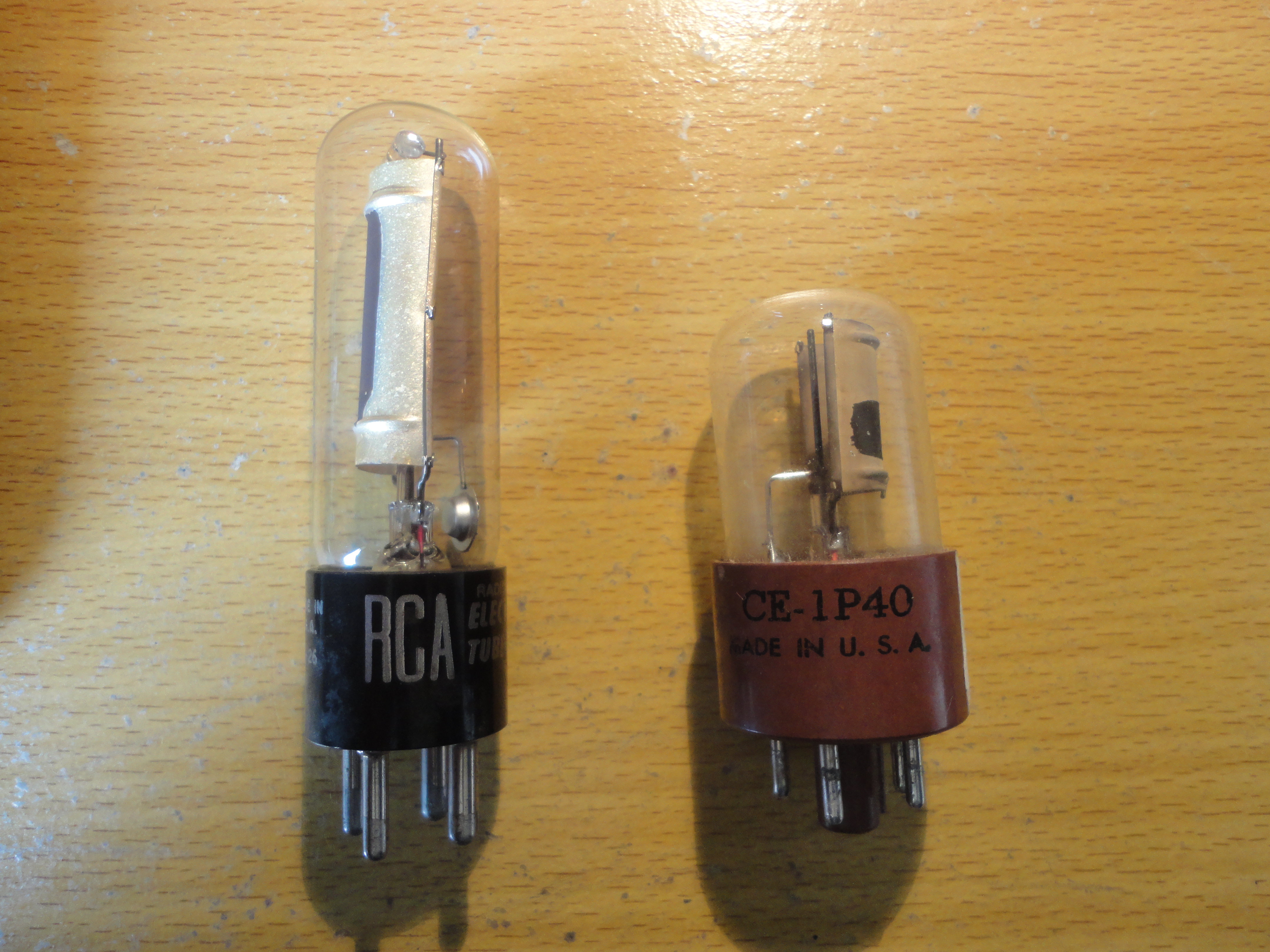
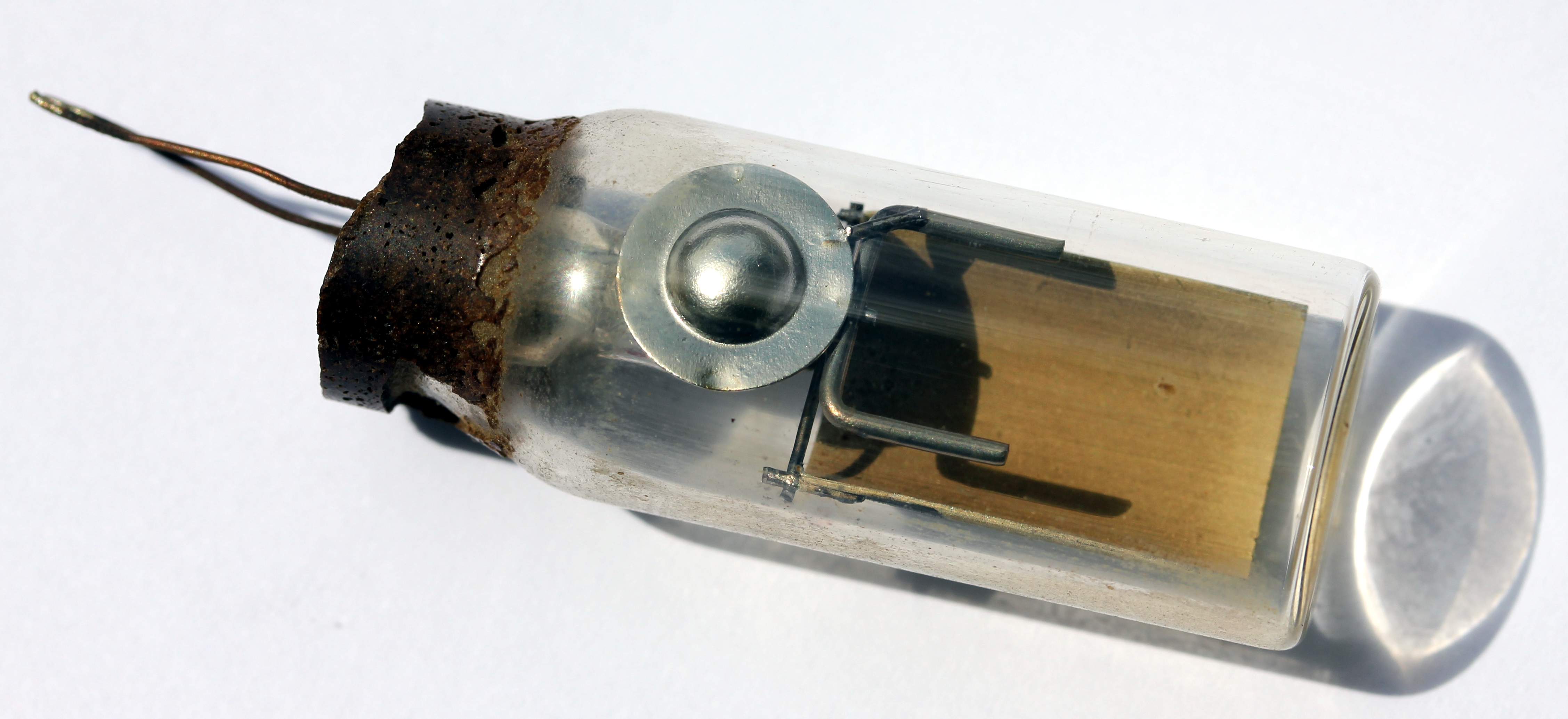
Here is an old vacuum tube photo cell. intact but the tube had become loose from its socket: :
Gas-filled photo cells, as used a.o. in fimprojectors with optical sound track:
This one, removed from a Siemens 16mm film projector because its signal had become way too weak. Although one may encounter such original photocells from the fifties, it will be of little use to try them out: photocells , as used for picking up optical sound in film projectors with an optical soundtrack, are gas-filled vacuum tubes. They are severely sensitive to aging and the sensitivity of them now, is -after our own findings and measurements- worse than 32dB down. The cathode most often uses a layer of cesium deteriorating over time and exposure to radiation. Also, tube photodiodes are very prone to mishandling: if ever the voltage over them reaches the ignition voltage threshold, they glow up and are thus destroyed right away... Normal working voltages are in the range of 50V to 90V and the cells have to be used with a very high series resistor (> 1MOhm). The dark current for a good cell ought to be in the range of 0.1uA, but of course exact values ought to be read from the datasheets for the individual photo cells. In the industry gas filled photocells have since long largely been replaced with by far superior semiconductor types. For very specialised applications (radioactivity measurement with Geiger-Mueller tubes is an example) some types are still produced.
Solid state semiconductor photodiodes and transistors
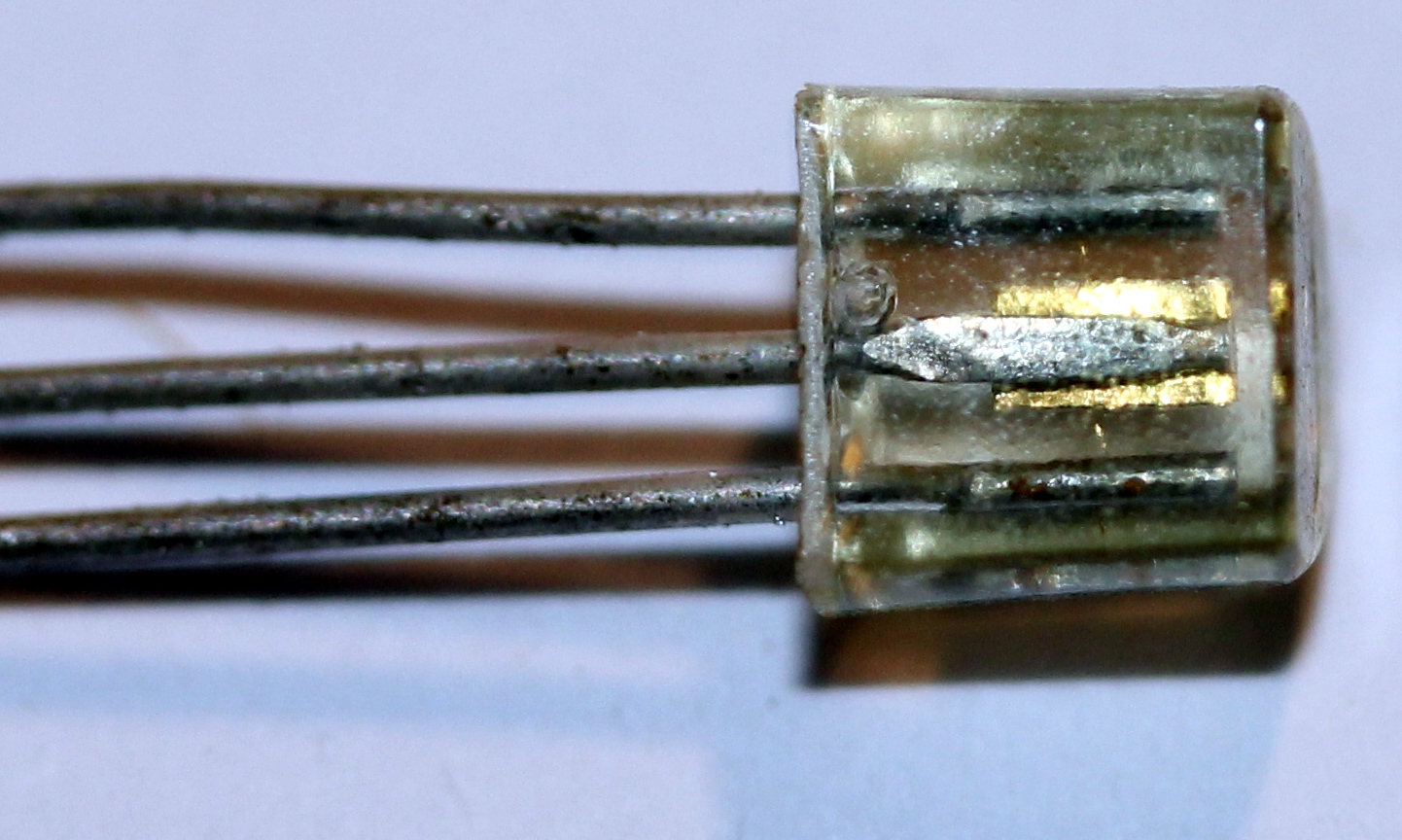
Semiconductor photodiodes and transistors have been available since at least the early sixtees. That was not such an invention as the photosensitivity of PN junctions was already observed long before and in fact many early applications using phototransistors, make use of ordinary transistors wherefrom the black lacquer was removed. Types that were often used as phototransistors where the Germanium transistors OC44, OC70, OC71, OC72. The OP-types where specialy made for their photoelectric properties. Semiconductor diodes in a glass packages are also inherently light sensitive and here again, special photodiodes are also produced.
A photodiode can be run either in photovoltaic mode (when run in forward bias) or in photodiode mode (when run in reverse bias). Photodiodes are normally run in reverse bias as this provides a linear response, and the responsivity range can be quite large. Avalanche photodiodes are also available and are always intended to operate with bias very near the reverse breakdown voltage. Once light is incident on the device, the number of photo-generated carriers is multiplied by the external bias as the device runs beyond the breakdown voltage. This produces gain during illumination. These photodiodes are designed to run in breakdown and are useful for detecting weak optical signals. They are less responsive and thus not used for audio applications. Photodiodes alongside an amplifier and analog-to-digital converter can also be used to receive digital data encoded in amplitude-modulated light or in PWM optical pulses. In the case of PWM, the bandwidth of the photodiode and amplifier have to be high enough as this limits the maximum data rate. The response time of a photodiode is related to its terminal capacitance. The higher the capacitance, the slower the device. The maximum response frequency is typically taken as the knee frequency for a digital pulse with a particular rise time, which is equal to 0.35/(response time).
Photo diodes require a current preamplifier in order to be of practical use. Typical circuits look like this:
We see no reason for not using semiconductor or photoresistive sensors if it comes to performing practice of pieces and installations originally using vacuum photodiodes. However, it still seems important to understand the working and specifications of the original components in order to replace them with modern components. In particular the spectral sensitivity is an important parameter as not all photodiodes or transistors work on visible light. Many types are only sensitive to infrared radiation.
Phototransistors are available as well and their use is pretty much the same as photodiodes. However, they tend to be somewhat slower. Their sensitivity can be set to a particular range, by applying some base current. Most often though, they are used with the base left unconnected. Here are some specimens:
If you are shopping for these components, look at the datasheet to get information on the spectral sensitivity. Many types are specified for the infrared range rather than for visible light. If you are replacing an old and obsolete component, often it will be a P-channel Germanium type. P-channel phototransistors are rare now, but redesigning the circuit to operate with N-channel components is not too difficult.
Photovoltaic cells - solar panels
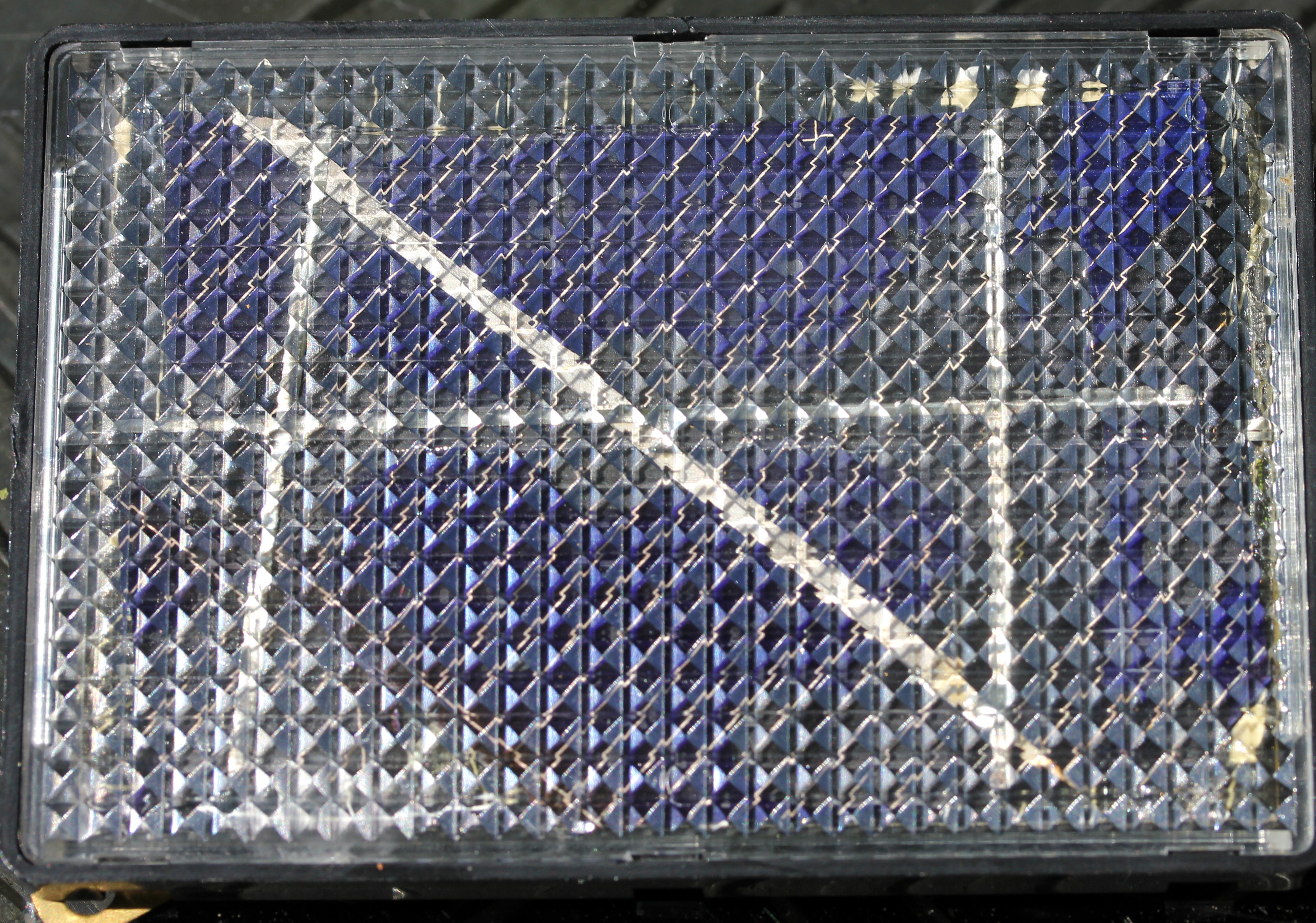
This picture shows an original solar panel as sold by Radio Shack in the mid seventies:
It is fully unprotected and the six elements that make the panel glued to a piece of insulating impregnated hardboard, are connected in series on the perforated back side. Plastic protected solar panels became available from the same source a few years later:
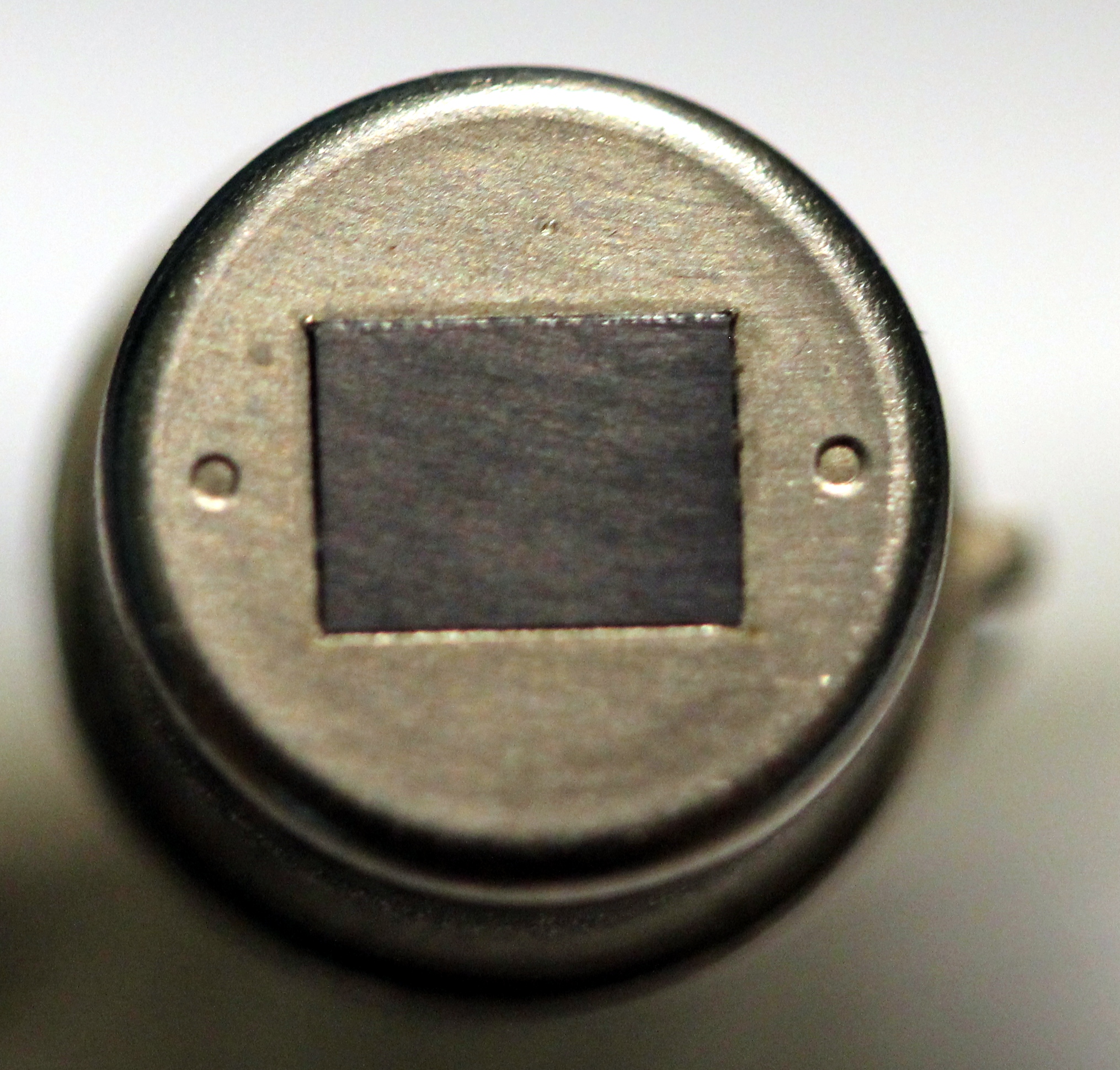
As a replacement for a vacuum photocell in an old filmprojector with optical sound, a small piece of solar panel can be used:
In general, such pieces of polycrystaline photovoltaic cells can be used to convert modulated light to sound. The voltage output range is almost independent from the crystal size, but the delivered current certainly is. For the specimen shown here, the maximum output voltage was ca. 500mV. Preamplification poses no specific problems and even direct connection to mixing desks is possible. The only problem one will encounter is to solder connections to the material. Note that a special type of solder must be used to do this! Regular Sn-Pb solder definitely does not work here. The French sound artist Jacques Dudon uses them as the core of his optophonic concerts and installations.
We rebuild a bunch of old 35 mm photo and 8 mm fimcameras by turning then into 'optosound' cameras, just replacing the spot for the film with an equivalent surface of a photovoltaic cell. The optics remain what they are and can be used for diafragm (this becomes signal output) and focussing. This was done for a composition wherein we needed to turn the movement of very large steam engines and airplane motors into sound. Thus we could 'amplify' the sound of the flywheels, the Watts regulator, propellers and cylinders of these huge machines. They can also be used to make solar eruptions audible. This was done in performances by Pauline Oliveros and others. If you want to amplify and listen to the stars, we can tell you this is barely possible as the sensitivity is too low...
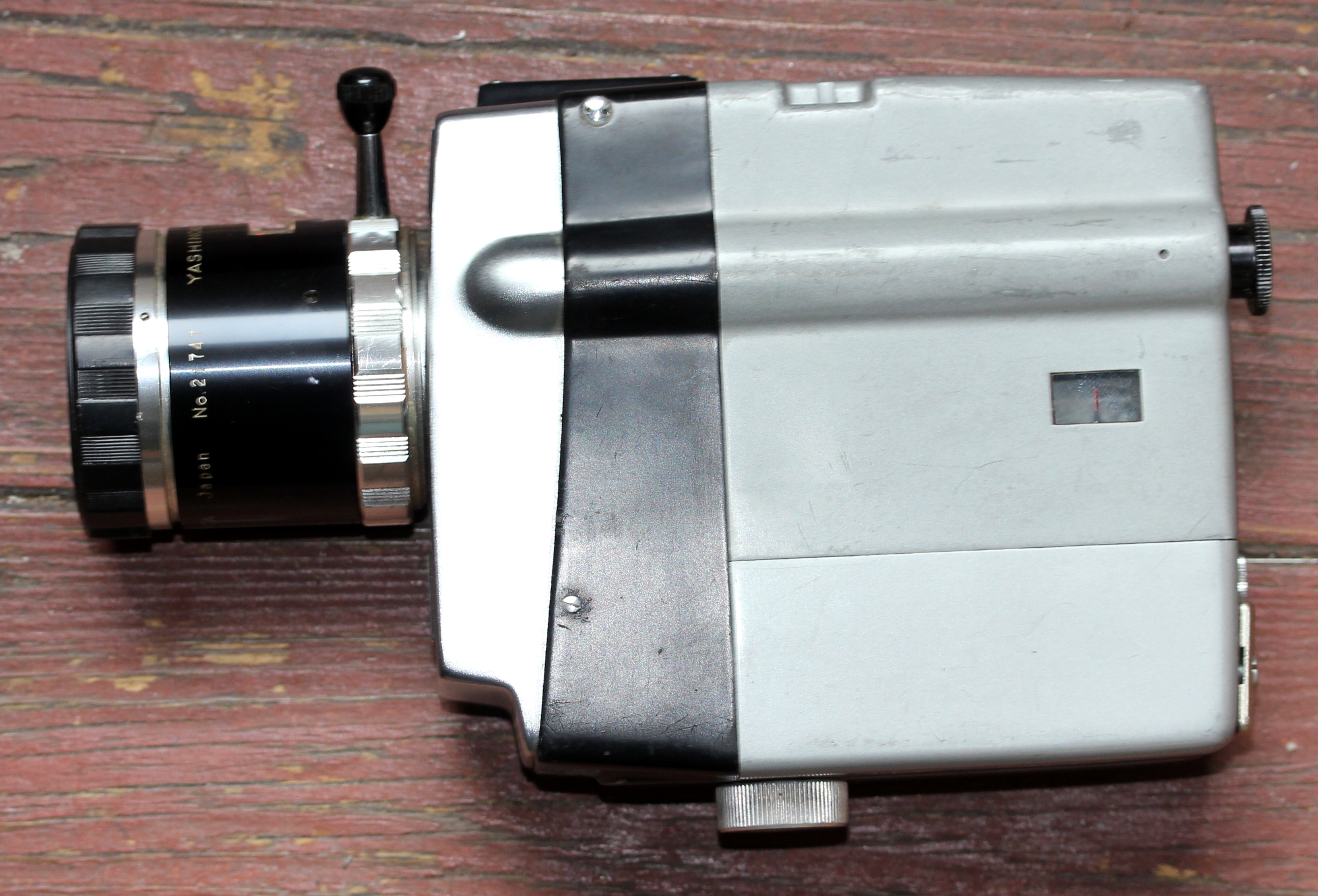
Both 'optoson' cameras in the picture, have a balanced XLR output and make use of phantom powering just like regular capacitor microphones. In the camera on the first picture, we preserved the camera housing and used its internal space to hold the preamplifier. In the second picture, we disposed of the original camera body altogether and just kept the optics, mounted on a standard BIM box.
Light dependent resistors (LDR's)
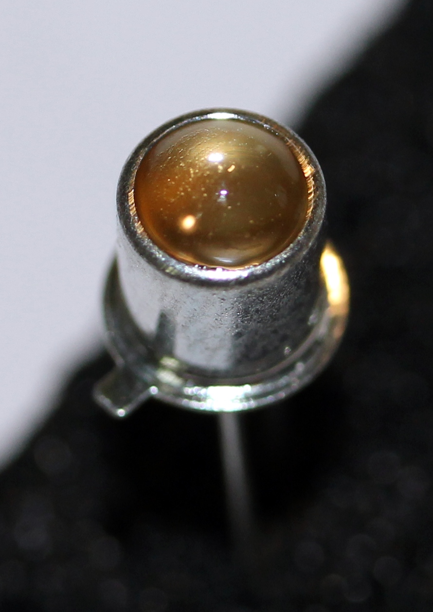
For many applications, LDR's can be used although it must be said that in a short time from now, they will also become obsolete and their production even outlawed as they contain a substance toxic to the environment: cadmium sulfide. These components have been around since the sixtees and the first types were quite large, some even encapsulated in glass just like a vacuum tube:
Modern ones look like this:
. They found astonishing many applications in audio devices such as guitar or organ volume pedals, amplitude modulators, audio choppers... They always have been very popular amongst electronics enthousiasts as they are very easy to use and calculate. Their dark resistance is ca. 1 MOhm but can reach 200 MOhm for certain types. The smallest resistance values are around 100 Ohms. The light versus resistance curve is far from linear and their application in audio circuits may introduce some non-linear distortion. Furthermore, their response to changing light conditions is highly assymetric. The light to dark transition may take up to 10 seconds, whereas the dark to light transition happens within some tens of miliseconds. For many designs this has been considered an advantage as it kills all risks for glitches that invariably accompany fast changes of audio signal levels. Hence their use also in compressor and limiter circuits.
Some very simple, yet reliable circuits and circuit ideas as we encountered them through our performance experiences:
Circuit to enable or disable audio when someone of something obscures the LDR sensor:
Of course these or similar simple circuits can also be used to steer control voltages for synth-like equipment modules such as VCO's, VCA's, VCF's...
Properties:
speed: diodes are fastest
signal: phototransistors
photovoltaic cells
slow: photoresistors (LDR)
Musicians and composers having used photo cells and optical sensors before 1980:
David Tudor, Jacques Dudon, John Cage, Richard Lerman, Nam Yun Paik, David Behrman, Wolf Dieter Truestedt, Hans Otte, Walter Giers, Jerry Hunt, Michel Waisvisz, Jozef Anton Riedl, Dick Raaijmakers, Lucien Goethals, Takehisa Kosugi
Pyrodetectors
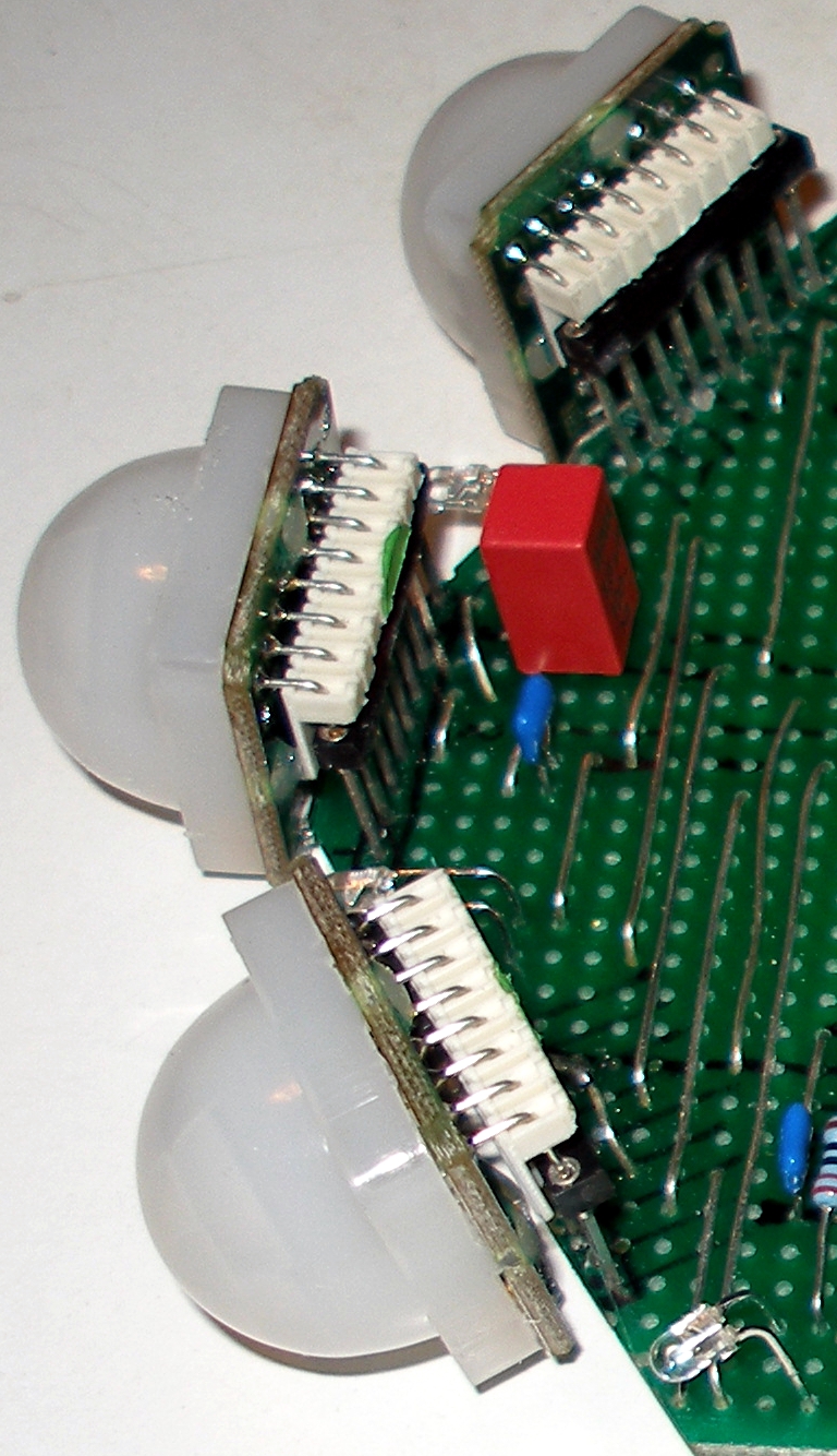
These semiconductors form a category of their own in the area of optical sensing. They are sensitive to infrared radiation with frequencies corresponding to the ones emitted by living bodies of humans and warmblooded animals. Although invented by Herbert Berman in 1970, the first working commercial specimens were introduced on the market in the early 80ties. As early as their availability on the market, they have been used as triggers in live-electronic interactive setups. They are not very suitable for gesture sensing as to that purpose they are way too slow. The fastest signals they can possibly generate are below 4 Hz. However they are a reliable solution for the detection of moving human bodies in a given area and within distances up to 10 meters.
In itself, infrared technology seems very promising if it comes to detecting moving live bodies since here we work with the radiation emitted by these bodies directly. Human bodies normally are at a temperature of 37 degrees Celsius (310.15 °K) and hence must radiate electromagnetic waves with a frequency spectrum showing a maximum at fm= w.T , according to Wien's law. In this relation w, derived from Wien's constant, equals 1.035E11 Hz/°K and T the absolute temperature of the radiating body. Thus, for a human body we come at a frequency maximum of 32THz corresponding to a wavelength of 9.368µm. The emission power, a normalized factor ranging from 0 to 1, equals unity only for a perfectly black body. This leads to the funny conclusion, that a sensing system based on body radiation works about twice as well for black people as compared to whites...(note 6). Obviously, this only applies when their bodies are not insulated from the environment with clothing. This frequency is in the very lowest part of the infrared spectrum. These frequencies are too low for detection by common infrared diodes, designed to operate somewhat below the visible spectrum of light, generally between 620nm and 950nm. Pyrodetectors, using a completely different technology mostly based on ferroelectric properties of triglycine sulfate (TGS), can detect this radiation range very well, showing sensitivities ranging from 7µm to 14 µm. The pyroelectric elements themselves are capacitive charge displacement devices and show off an extremely high impedance (ca. 100GOhm) and for this reason they are always produced directly coupled to the gate of a MOSFET. Due to this extremely high impedance, the sensing elements must show off a sensitivity inverse proportional to frequency. This means that it is inherently pretty slow, limiting frequency of input amplitude changes to below ca. 50Hz. In practice, the output signal is invariably low pass filtered to below this frequency, mostly to suppress the 50Hz mains frequency component. Note that typical output voltages for these sensors are below 450µV. (note 7) The problem in using these detectors for body sensing, is that the spectrum is obscured by many other low infrared sources in the environment, since emitted spectra are continuous and therefore objects at higher temperatures will also emit waves in the band we are interested in. Thus the received signal gives only a measure for the overall intensity of the radiation. For this reason, it would not suffice to place a very selective filter in front of the sensor. By using focussing optics, it is possible to measure temperatures on a small spot, as used in remote thermometers, but this does not help us for developing movement sensors. Rescue comes from another consideration: if the radiating bodies move, we can discriminate the emitted signals by placing a fine fresnel lens in front of a sensor composed of at least two sensing elements. This is the fundament behind the design of PIR sensors, reacting only to changes in the frequency range of interest. This also seems to entail that the differential signal amplitude should correspond to the distance between body and sensor, since the surface of a body remains pretty constant. The relation, in theory, follows a square law. It also appears that it should be easy to determine the precise angular position in space, given a suitable lens system. For the latter, in regular PIR devices, Fresnell lenses placed in front of the pyrodetector are invariably used. For good hemispherical sensing, the sensor should be internally composed of four elements. Angular speed seems derivable from the frequency of the output differential signal. The newest PIR sensor we examined was the PIR STD (Order number CON-PIR-STD-172526), claiming a sensitivity up to 12 meter. After the data sheet, we get from the analog outputs a signal with a frequency between 0.2Hz and 10Hz, proportional to detected angular speed. The resolution is pretty low as it is determined by the optical characteristics -the number of bands- of the Fresnell lens used. In this case, the data sheet gives 11 bands horizontal with a spacing of 10 degrees and 5 bands vertical, with an unevenly distributed spacing of -30, -20, 0,+20 and +30 degrees. This signal is symmetrical around the halved power supply voltage, but the circuit provides in a second analog reference output used internally as Vc/2. This provision makes interfacing to a microcontroller pretty simple. The sensitivity angle is ca. 100 degrees, horizontal. In the vertical plane it is 60 degrees. A digital output is available as well, derived from a simple window comparator circuit in the sensor module.
Better sensors using this technology may become available in the near future, the range of potential applications being quite large. In our wildest fantasies, it seems possible to design and fabricate a (sort of) CCD chip composed of say 1000x1000 round pixels, each a little smaller than 10µm in size such that each pixel could be tuned to resonate at the wavelength of 32THz. Such a chip substrate, preferably in a triangular 60 degree arrangement, would measure 1 square centimeter, and due to the small size of the pixels, respond quickly. The required mosfets can, with available technology already be fabricated on chip. The read-out logic could profit from already existing designs for CCD cameras. After we wrote down this dream, we discovered that devices implementing this approach actually do exist, but not only in as far as they can be bought by private persons or institutions, are extremely expensive but also, they all fall in the domain of military technology. Some relevant links: http://en.wikipedia.org/wiki/Thermographic_camera as well as http://en.wikipedia.org/wiki/Night_vision_goggles. If you delve any further you enter into military domains. Who takes up the challenge to produce something more constructive?
(6) This only under the assumption that black people can effectively be considered more black than white people for the wavelengths we are talking about here, an assumption that needs to be proved by experiment. So, don't take it for granted.
(7) Cf.. datasheets for the RPW100, RPW101, RPW102, RPY100, RPY102, RPY107, RPY109, RPY222 devices in the Philips Semiconductor Sensors databook, volume SC17, 1989 edition.
Musicians and composers known to have used pyrodetectors in their compositions and/or performance practice:
Jerry Hunt
Video cameras, Vidicon tubes and CCD sensors
We mention these clearly optical devices here for completeness sake, without discussing them for we know no composers but one -Jerry Hunt (1943-1993)- that used them in their performing practice. The only other exception could be Nam Yun Paik, but in his case, it would much rather apply to his video and installation work, than to musical work he made. Of course we are not referring to composers having used video as such in their composition or performances, as such 'normal' use poses not the slightest problem with regard to historic performance practice.
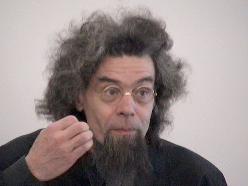
As to Jerry Hunt, we have known him pretty well and have discussed technical stuff a lot with him, we must state that he didn't leave any technical details and even the scores he left are so obscure that it barely makes sense to try to perform them. The only thing one could do is, based on the video's and recordings of his performances, attempt to reconstruct them. We doubt such reconstructions would be convincing given the strong scenic personality of Jerry Hunt himself.
Microwave and radar sensors
Microwave based doppler radar sensors have been available since... [military restriction...]
Used as alarms and for home automation.
Used a lot in the shamanistic performances between 1978 and his death, by the American composer Jerry Hunt (1943-1993)
Ultrasonics
Ultrasound in performance : bat's, holosound bells, Tinti, Chi
Ultrasound based gesture recognition technology
parts of this paragraph also in the case-studies article under John Cage. It may be better placed here...
For interactive applications -more specific, for productions with Merce Cunningham and his dance company- Cage has been using photocells. He nowhere gives more specifications about them, but we are sure he confined the technical details to his collaborators some of which were very knowledgeable in electronics: David Behrman, Takehisa Kosugi, Gordon Mumma to name just a few.
Installations and scores mentioning photo cells should be re-engineered with a good understanding of the function they fulfilled in the period-equipment or setup. Phototransistors can be used, but their use is a little more involved: they need some kind of a circuit and their output is a voltage or current. Often, for instance if the photo cell is used as a sound generator, picking up amplitude modulated light, an excellent solution consists of using a solar cell. These are in their common appearance in general way too large, but it's quite easy a break off a small part,
This article is part of a research project on Experimental Legacy financed in part by the Orpheus Institute in Ghent.
Last update: January 4th 2023
www.orpheusinstituut.be