Dr.Godfried-Willem RAES
Kursus Experimentele Muziek: Boekdeel 2: Live electronics
Hogeschool Gent : Departement Muziek & Drama
| <Terug naar inhoudstafel kursus> | MOTORS | Dit hoofdstukje is niet beschikbaar in het nederlands. |
2117
In automation and instrument building we often are confronted with the necessity to precisely controll rotational speed of a strong motor. In principle DC-motors are the easiest to handle in this respect. Their speed can be controlled as a function of applied voltage, the direction of rotation by the polarity of this voltage. However DC motors are plagued with a lot of annoying characteristics, such as mechanical noise, wear of the collector brushes, torque dependent on voltage/speed, unstability of speed (speed depends on load) etc...
For small power motors DC-types still remain easy to handle, since we can controll many deficiencies by electronic design. Schematics of quality cassette decks offer good examples for those interested. These little motors are indeed very cheap...
As to higher powers, the advantages of AC motors are obvious: synchronous and asynchronous motors are available in all power categories imaginable. They are inherently more silent than DC-motors since there are no contacts between stator and rotor. However, almost all of them require the user to feed them 3-phase current... (Single phase motors circumvent this problem one way or another, for example, by feeding one of the windings via an expensive AC capacitor, such that a 2-phase current is created). 3-phase motors have optimum efficiency and are by construction cheaper than their monophase counterparts. Also, for high power (say above 1kWatt), the use of monophase is cancelled out.
Schematically 3-phase motors can be connected as this:

Note that a motor rated for 400V can be operated at 230V if connected in star. A motor rated for 230V in delta connection, is generally meant for a 230V/SQR(3) = 132V. The voltage difference is always exactly a factor SQR(3), inherent to 3-phase current. Very large motors require -in order to minimize the current at start-up- a star/delta switch: they start in star connection with a lower than normal voltage across the windings and once they run at a certain speed, are switched over to delta connection with the full voltage over the windings.
Now the problem with this type of motor is that the rotational speed is not a function of applied voltage, but of AC frequency! Thus, in order to controll the speed of such motors we have to find a way to feed it a precisely controllable frequency current. Furthermore, for 3-phase motors, this current should be presented in 3-phases with a mutual phase angle of 120 degrees. Whereas at first sight this all seems complicated, it becomes pretty easy if we use the wealth of features available through digital electronics.
Although it is not impossible to generate 3 sinewaves (one could use a simple sine lookup table), 120 degrees out of phase, of variable frequency, we most often do not have to go that far. After all the windings of a motor are coils and have a low-pass filter characteristic. As a result of this, it is quite possible to feed these motors with square waves. If we use 3 single bit lines from a processor, then it will be understood that the following pattern (if looped at a given frequency) in fact is nothing else than the 120 degree shifted 3-phase current!
| step 1 | step 2 | step 3 | step 4 | step 5 | step 6 | |
| bit0 | 0 |
0 |
0 |
1 |
1 |
1 |
bit1 |
0 |
0 |
1 |
1 |
1 |
0 |
bit2 |
1 |
0 |
0 |
0 |
1 |
1 |
Making a computer generate this pattern on an output port is as simple as it can be. However, the signals the computer generates are TTL, say 0 to 5V at maximum 10mA. Our motor would not even notice the presence of such a voltage if we fed it with this...
Thus we need a way to turn this signal into a strong and hefty power source for the motor. Nominal voltages on which 3-phase motors do run (in Europe) are 230V/400V. This should be understood from studying the simplified schematic of a motor. If the windings are connected in a delta configuration, the motor has 400V across the windings. In star connection, a common point to all three windings is the 'neutre' of zero conductor (the average current at this point equals zero) and the other ends of the windings are connected to the 230V phase sources of the mains.
In order to use our microcomputer to generate this kind of voltage, we nowadays can use power MosFets capable of handling up to and over 1000Vdc at currents of 6 to 40Amps...
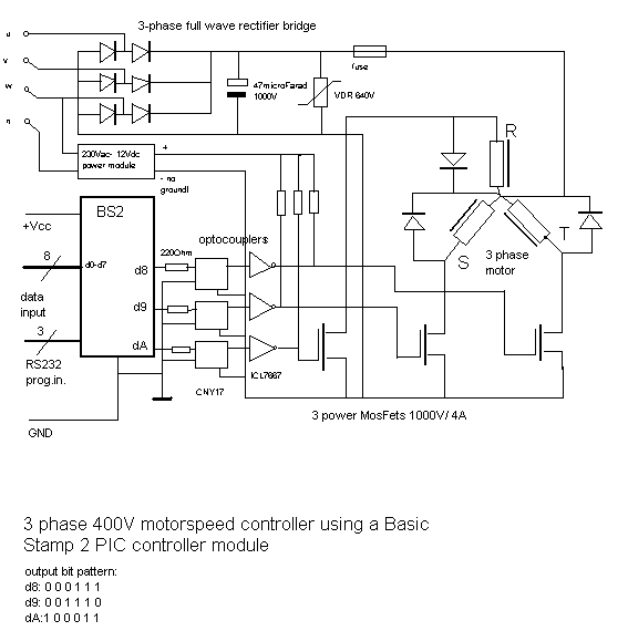
First thing to be done, consists of rectifying the 3-phase mains voltage using a bridge rectifier (6-diodes required). This becomes the power supply we will use and switch using the MosFets in the pattern and order dictated by the microcomputer.
For safety reasons it is not only advised to use optocouplers, it should be considered really mandatory! There should be a complete galvanic insulation between the digital controll part of the circuit at the one hand, and the power electronics + motor circuitry at the other. Do not ground any part (except of course , the cabinet) of the high power section of the circuit!
A principle design for a motor controller using a single BS2 Basic Stamp controller looks like this:

This circuit accepts 8-bit information at its input. This data may come from a computerport such as the printer-port, or, as was the case in one our applications, from a microprocessor accepting midi-input and converting this into parallel format. The frequency at the output is equivalent to this numeric value, minus processing losses.
The (pseudo) code looks like this:
- DO
- frq = INP(adres) :' byte input
- T = 1000 / (frq * 6) :' in milliseconds
- OUT 0
- wait T
- OUT 2
- wait T
- OUT 3
- wait T
- OUT 7
- wait T
- OUT 5
- wait T
- OUT 4
- wait T
- LOOP
Of course, in order to make this run on a Basic Stamp, this code has to be translated into the ideosyncratic Basic dialect the BS2 understands.
PS:
1.- Monophase motors using a capacitor can be controlled this way also, but there is a danger to this practice: the capacitor is normally calculated to yield a fixed fase shift at the nominal working frequency. When the frequency applied is way off the nominal value, the proper fase is no longer maintained by the cap. This can have at least two nasty effects: the cap may heat-up and explode at high frequencies, the motor may get very hot and eventually burn out! Exploding caps can be really dangerous!
2.- limitations: due to mechanical restrictions one has to be cautious in driving up the speed of a given motor far beyond the nominal speed. Although at higher frequencies, the current will decrease (remind you, we are sending ac through a coil...), the windings may no longer withstand the centrifugal forces developped.
At the low end, there are limits also: first of all the motor will no longer run stable and may start stuttering. Also, since we have lowered the frequency, the current will be higher, leading to more heat in the windings. To compensate for this, one should also lower the voltage.
Within the range +/- 50% of the nominal frequency, one will rarely encounter such problems however. Simply, do not exagerate!
3.- In older textbooks, the nominal voltage in Flanders was stated as 220V, yielding 220V+ SQR(3)= 380V in 3-phase wiring. Nowadays the standard mains voltage has risen to 230V, or 400V in 3-phase wiring. This slight rise in voltage rarely has adverse affects on our motors. It just makes the power station send us a slightly higher bill, since we pay for the power delivered.
Application example:
1.- controlling a Laukhuff radial compressor, feeding wind into a pipe organ, via a midi continous controller. Within certain margins, the wind pressure in the organ can thus be controlled. In our experience, the margins with such turbines are + 20% to -60% and below.
More information: Barrelorgan.html
2.- Construction of a precize and tunable mechanical siren using a motor.
3.- Operation of 3-phase motors from aircraft (these work on a nominal 400Hz 3-phase current!). We had a bunch of nice axial blowers from a surplus store, that we used to provide the wind for very large wooden organ pipes, one blower for each pipe!
4.- Three phase motor controller with BS2 basic stamp, using a 230V to 400V separation transformer, for 230/400V motors connected in star.
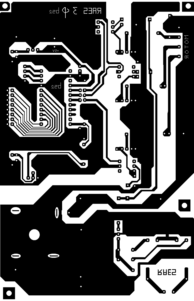
For this example we designed a simple single sided PC board. The heatsinks for the TO220 packed power mosfets are mounted upright.

A complete circuit drawing for this PC board looks like:

The source code for the microcontroller can by retrieved by clicking this link to our Stamp directory.
Further reading:
It is quite hard for students into electronic circuitry -let alone those into electronic musics- to get information with regard to high voltage and high power circuitry. We do not know of a single electronic engineering handbook, where students can find, for instance, configuration details and calculations for 3-phase rectifier bridges! If readers are in need of further materials, go to machine controll and power station electric engineering libraries and literature. Circuits dealing with very high current/voltage can be found in forklift trucks, welding equipment, cranes, ships, trains...
Application notes for high power MosFets (Harris, Intersil, Philips) also often provide interesting examples in this area.
If readers are interested in some of our professional designs for driving > 2kW motors, look into the Logos website and search for the pages on <Balmec>, a project whorefor we designed three motor driven airplane propellers.
Filedate: 98-09-07 last update: 2017-05-27
| Terug naar inhoudstafel kursus: <Index Kursus> | Naar homepage dr.Godfried-Willem RAES | Deze pagina is niet beschikbaar in het nederlands |